element14 Community
element14 Community
    Register Log In
  • Site
  • Search
  • Log In Register
  • Members
    Members
    • Benefits of Membership
    • Achievement Levels
    • Members Area
    • Personal Blogs
    • Feedback and Support
    • What's New on element14
  • Learn
    Learn
    • Learning Center
    • eBooks
    • STEM Academy
    • Webinars, Training and Events
    • More
  • Technologies
    Technologies
    • 3D Printing
    • FPGA
    • Industrial Automation
    • Internet of Things
    • Power & Energy
    • Sensors
    • More
  • Challenges & Projects
    Challenges & Projects
    • Design Challenges
    • element14 presents
    • Project14
    • Arduino Projects
    • Raspberry Pi Projects
    • More
  • Products
    Products
    • Arduino
    • Dev Tools
    • Manufacturers
    • Raspberry Pi
    • RoadTests & Reviews
    • Avnet Boards Community
    • More
  • Store
    Store
    • Visit Your Store
    • Choose Another Store
      • Europe
      •  Austria (German)
      •  Belgium (Dutch, French)
      •  Bulgaria (Bulgarian)
      •  Czech Republic (Czech)
      •  Denmark (Danish)
      •  Estonia (Estonian)
      •  Finland (Finnish)
      •  France (French)
      •  Germany (German)
      •  Hungary (Hungarian)
      •  Ireland
      •  Israel
      •  Italy (Italian)
      •  Latvia (Latvian)
      •  
      •  Lithuania (Lithuanian)
      •  Netherlands (Dutch)
      •  Norway (Norwegian)
      •  Poland (Polish)
      •  Portugal (Portuguese)
      •  Romania (Romanian)
      •  Russia (Russian)
      •  Slovakia (Slovak)
      •  Slovenia (Slovenian)
      •  Spain (Spanish)
      •  Sweden (Swedish)
      •  Switzerland(German, French)
      •  Turkey (Turkish)
      •  United Kingdom
      • Asia Pacific
      •  Australia
      •  China
      •  Hong Kong
      •  India
      •  Korea (Korean)
      •  Malaysia
      •  New Zealand
      •  Philippines
      •  Singapore
      •  Taiwan
      •  Thailand (Thai)
      • Americas
      •  Brazil (Portuguese)
      •  Canada
      •  Mexico (Spanish)
      •  United States
      Can't find the country/region you're looking for? Visit our export site or find a local distributor.
  • Translate
  • Profile
Experimenting with Magnetic Components
  • Challenges & Projects
  • Design Challenges
  • Experimenting with Magnetic Components
  • More
  • Cancel
Experimenting with Magnetic Components
Blog Experimenting with Magnetic Components - Boost Converter part 1: Inductor and Calculations
  • Blog
  • Forum
  • Documents
  • Mentions
  • Sub-Groups
  • Tags
  • More
  • Cancel
  • New
Blog Post Actions
  • Subscribe by email
  • More
  • Cancel
  • Share
  • Subscribe by email
  • More
  • Cancel
Group Actions
  • Group RSS
  • More
  • Cancel
Engagement
Author: Jan Cumps
Date Created: 2 Oct 2021 11:23 AM
Views: 507
Likes: 0
Comments: 9
  • experimenting_with_magnetic_components
  • magnetic_components
  • bourns
Related
Recommended

Experimenting with Magnetic Components - Boost Converter part 1: Inductor and Calculations

Jan Cumps
Jan Cumps
2 Oct 2021

I'm reviewing a set of inductors for the Experimenting with Magnetic Components design challenge.

Because it's a design challenge, I'd like to start with a working product. A switch mode DC converter.

It's one of the standard circuits: the boost converter. A design that increases a DC voltage.


Goals:

  • 9 - 12 V DC input
  • 30 - 60 V DC output
  • up to 20 mA output current
  • max 200 mV ripple
  • common components
  • no regulation or feedback


But first:


Post 1#: Introduce yourself and explain what experiments you plan to perform

I live in Schaerbeek, Belgium and have studied electronics, measurement & control techniques, and information systems.

My theme is "grow the love for inductors as LAB project building block".

  • What they do
  • Where you use them,
  • Review the inductors in the kit
  • How to measure, without LCR meter
  • How to use an LCR meter
  • How to roll your own coil, your own little transformer
  • PCB transfo


Back to the story:


The inductor: Bourns RLB Series 1mH Radial Lead InductorBourns RLB Series 1mH Radial Lead Inductor


image: Bourns RLB0914-102KLRLB0914-102KL 1MH inductor with candidate MOSFETs


The datasheet is available on element14. All info is taken from that document.

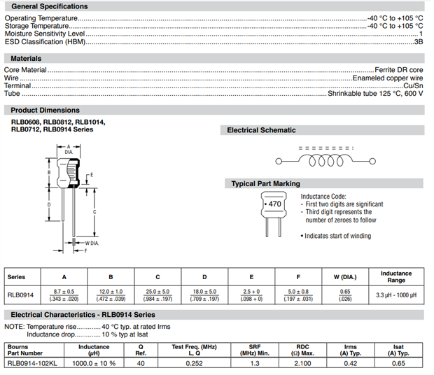
image: the specifications of the 1mH inductor


Measurements on the component in my kit:

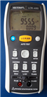
The datasheet did the measurements at 252 KHz. I'm doing them at the maximum setting of my meter: 100 KHz.

The meter (comparable with GW INSTEK LCR-916) was calibrated before the measurements.

Results (f = 100 KHz)


L:955.5µH

Q:  106.5

D: 0.009 (1/Q)

ϕ: 89.4°

ESR: 5.64 Ω


The Boost Converter Calculations


I'm using the most common boost converter design. Adafruit (and others) posted a calculator online.

I used that, and changed parameters until the design matched the 1 mH inductor.


image source: calculation done with the Adafruit boost converter calculator.


Whe in I use a switching frequency of 72000 Hz, the calculator suggests exactly 1 mH.

Texas Instruments has an application note on the calculations.

Coursera has an excellent Power Electronics course, from U of Colorado Boulder.


Hang on while I'm starting the build.


Related posts
1. Boost Converter part 1: Inductor and Calculations
2. Boost Converter part 2: Build
3. Boost Converter part 3: Measure the Inductor in action
4. LCR meter experiments
5. SMD transformers experiment gizmo part 1: Build
6. SMD transformers experiment gizmo part 2: Measure
7. Common Mode Choke
8. Make your own Inductor
9. Calculate your own Inductor
10. Boost Converter part 4: Efficiency
11. DIY Inductance Meter
Planar PCB Transformer: GaN Point of Load converter 48V to 1V 50A
Measure Unknown Inductor Value with Function Generator and Oscilloscope
Experimenting with Magnetic Components: About the Competition
Anonymous
  • Jan Cumps
    Jan Cumps 7 months ago

    I ordered a set of easy-to-drive N-Channel MOSFETS to test the 2 pulse transformers of the kit. N-Channel On Semiconductor NTK3134N (Farnell 27244122724412)

    I should be able to control the FETs from this FPGA design (with an extra driver to up the gate to 6 V from 3.3 V): FPGA based PWM generator with scroll wheel control.

    • Cancel
    • Up 0 Down
    • Reply
    • More
    • Cancel
  • Jan Cumps
    Jan Cumps 7 months ago

    Some measurements of one coil of inductor #10 with LCR (100 kHz): Common Mode choke 9 µHCommon Mode choke 9 µH


    Inductance:

    Phase angle (θ):

    Dissipation factor (1/Q)

    Quality factor (tanθ, 1/D)

    Equivalence serial resistance:


    • Cancel
    • Up 0 Down
    • Reply
    • More
    • Cancel
  • Jan Cumps
    Jan Cumps 7 months ago


    80% duty cycle. Not all components are equal to the calculation, because I didn't have them.

    9 V -> 32 V

    • Cancel
    • Up 0 Down
    • Reply
    • More
    • Cancel
  • Jan Cumps
    Jan Cumps 7 months ago in reply to shabaz

    fixed

    • Cancel
    • Up 0 Down
    • Reply
    • More
    • Cancel
  • shabaz
    shabaz 7 months ago in reply to Jan Cumps

    Hi jan,

    Nice prototyping!

    Btw there's a typo, you mean 72000 Hz but have written 72000 kHz.

    • Cancel
    • Up 0 Down
    • Reply
    • More
    • Cancel
>
Element14

element14 is the first online community specifically for engineers. Connect with your peers and get expert answers to your questions.

  • Members
  • Learn
  • Technologies
  • Challenges & Projects
  • Products
  • Store
  • About Us
  • Feedback & Support
  • FAQs
  • Terms of Use
  • Privacy Policy
  • Legal and Copyright Notices
  • Sitemap
  • Cookies

An Avnet Company © 2022 Premier Farnell Limited. All Rights Reserved.

Premier Farnell Ltd, registered in England and Wales (no 00876412), registered office: Farnell House, Forge Lane, Leeds LS12 2NE.

ICP 备案号 10220084.

Follow element14

  • Facebook
  • Twitter
  • linkedin
  • YouTube