


|
I'm reviewing a set of inductors for the Experimenting with Magnetic Components design challenge. In this post: make a simple and cheap inductance meter.
w2aew has made a video (included later in this post) on this little design. The original comes from n4tmi, published in 73 magazine, September 1990). I'm trying it out, only using things I have at home.
The Bourns inductors #2, #7 and #15 of this kit will be used, and the custom one I made in post #8.
|

Short story: this is an oscillator.
The inductor under test in parallel with a known capacitor will have a resonance frequency.
This circuit will oscillate at that frequency. You measure that frequency at the output, then use a formula to derive the inductance of your unknown inductor.
Schematic, Layout and BOM
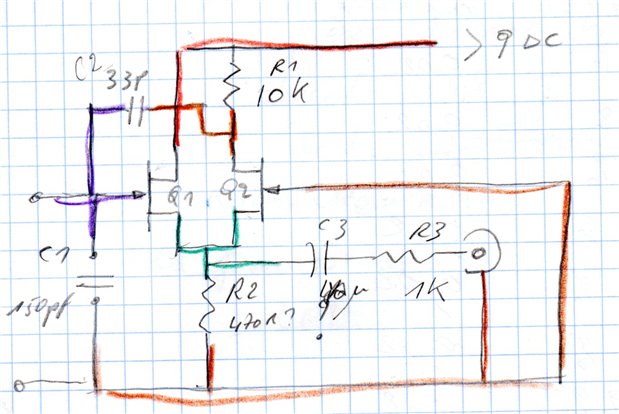
image source: drawing based on n4tmi's article in 73 magazine
Strongly simplified explanation. Check w2aew's video and n4tmi's article for details.
The Inductor Under Test and C1 (150 pF) form a resonant tank circuit.
C2 provides positive feedback to keep the oscillator swinging.
R2 puts Q2 in the saturation region. Like w2aew, I used 1K instead of the 470R in the original design.
The output can be checked with a frequency counter or an oscilloscope.
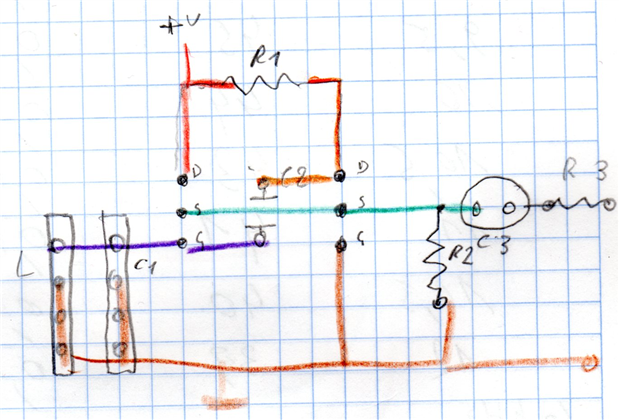
image: layout prepared on a piece of paper
I used perf board (part of a shopping cart I won with Project14). I placed components on a piece of paper first.
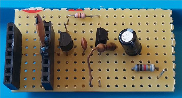
image: the circuit built up on a piece of perfboard
You can see that the final layout on the perfboard is a translation of that. I placed C3 the wrong way, may fix that later.
In the left slot you can place the inductor. The upper 3 pins are input, the lower 4 ground. In the right slot you can put the reference cap (C1).
These slots are interchangeable because both sides' inputs and grounds are connecting to the same circuit node.
If you want to measure the frequency of an unknown resonant circuit, remove C1.
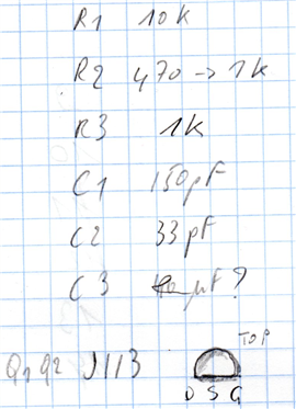
image source: BOM based on n4tmi's article in 73 magazine, except the JFET + drawing
Before continuing, let's enjoy w2aew's video:
video source: w2aew video #199
Try It
The circuit starts to oscillate when VIN is just over 9 V. I got the best results when the voltage was above 12 V. You can use it with two 9 V batteries in series.
I've tested it with 3 inductors from the Bourns kit, and with one I made myself.
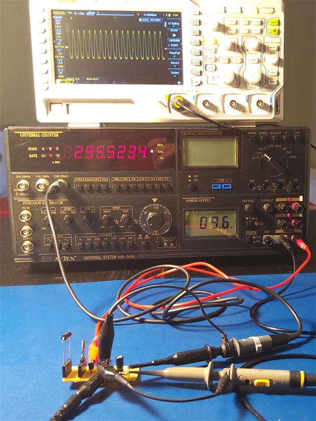
image: device in action, measuring frequency with a counter and an oscilloscope
I got reliable frequency measurements with an oscilloscope, a traditional frequency counter and with the EEVblog 121GW DMM.
The load at the output has little effect on the oscillator circuit, because the input impedance isn't affected by what you connect to the combined JJFET sources.
Before checking the individual tests, let's first check the formula to translate frequency into inductance.
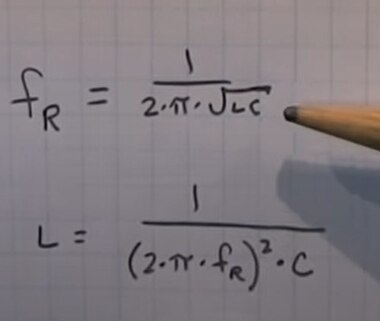
image source: still from w2aew video #199
The original article uses IBM Basic. I used a spreadsheet (attached)
Formula: =1/(POWER((2*PI() * E9);2)*E8)
where E9 is the measured frequency and E8 the value of known capacitor C1.
Test 1: Inductor #2, RF Choke, Radial Lead, Radial Lead, 3.3 µHRF Choke, Radial Lead, Radial Lead, 3.3 µH.
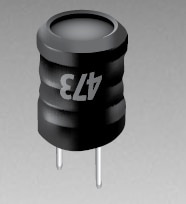
image: Bourns datasheet
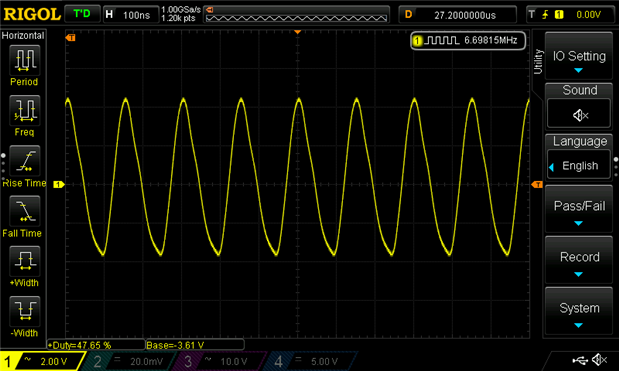
Frequency: 6.7 MHz
Result:
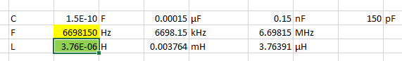
3.8 µH
Check with LCR meter at 100 kHz: 3.587 µH
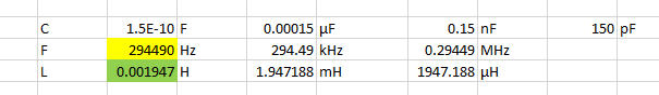
Test 2: Inductor #7, RF Choke, 1.8 mHRF Choke, 1.8 mH.
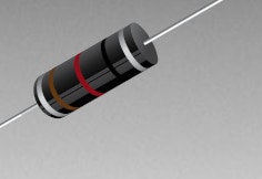
image: Bourns datasheet
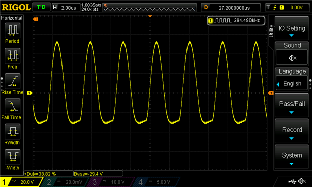
Frequency: 294.490 kHz
Result:
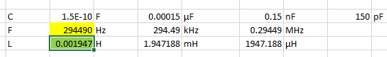
1.9 mH
Check with LCR meter at 100 kHz: 1.7349 mH.
Test 3: Inductor #15, Choke, 100mHChoke, 100mH.
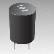
image: Bourns datasheet
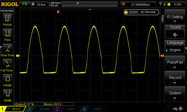
Frequency: 39.8 kHz
Result:
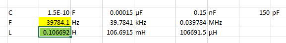
106 mH
Check with LCR meter at 120 Hz: 103.82 mH
Test 4: Own made, toroid 60 µH.
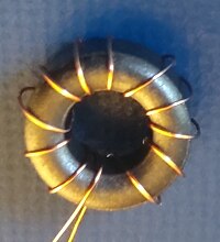
image: mine
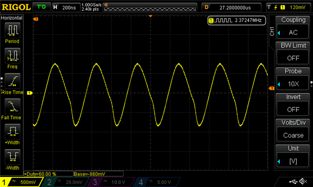
Frequency: 2.4 MHz
Result: (the oscillator wasn't stable like with the Bourns devices)

30 μH (see Jon's comment below)
Check with LCR meter at 10 kHz: 60 µH

