My previous “extra credit” blog embarked on the beginning of my journey to characterise supercapacitors through measurements of capacitance and ESR. While those are two important parameters, there are certainly other considerations when it comes to using supercapacitors in actual applications.
In this third “extra credit” blog, I’ll be discussing the results of leakage current measurements. I’ll also take a thought-experiment approach to sizing up a supercapacitor solution and try to understand some of the subtleties regarding supercapacitor lifetime. As a bonus, I’ll also do some indoor solar panel testing by running an I-V curve trace under intense LED illumination.
Table of Contents
Leakage Current & How to Measure
The leakage current of a supercapacitor is the current it draws when it is fully charged. This is usually a good indicator about the state of the internals of any capacitor and is of vital importance especially in energy harvesting applications where the leakage represents a parasitic load that is “wasting” away energy and competing with the load. I catalogued the supercapacitors we received and their datasheet characteristics – in all, we expect the leakage current to be in the one to several-hundred µA region.
Looking at Cornell Dubilier’s Technical Guide about leakage current:

One way to measure this would be to use a Source Measurement Unit (SMU) to supply the fixed rated voltage to the supercapacitor for a 72-hour period (to ensure it is fully charged) and measure precisely the small amount of current still flowing into the unit. The use of an SMU is recommended due to the small currents involved, requiring a rather precise measurement capability that is lacking in most power supply units (PSUs) and avoiding any issues with burden resistances.
However, such an approach is expensive as SMUs are not cheap – I only have one and if each capacitor took 72 hours to test, I’d need 78 days to test the whole lot. I don’t have 78 days …
Thankfully, I came across this simple “compromise” arrangement in an AVX datasheet:

Put simply, you can use a DC power supply and a sense resistor (1kΩ) that is shorted over for the first 72 hours. Once the time has elapsed, you remove the short so that the capacitor is powered through the sense resistor and you measure the voltage across the resistor after a ten-minute stabilisation period to know the current (1mV = 1µA). This method is not 100% accurate as there is a tiny burden voltage caused by the sense resistor that may mean that the leakage measured is a slight underestimate, hence the ten-minute stabilisation period to let everything equilibrate. The major advantage of this method is that it is simple, inexpensive, easily parallelisable and doesn’t require any high-end equipment.
Experiment #3: Leakage Current Measurements
Let’s measure leakage current using both methods – most of the supercapacitors will be measured using the AVX method while the two 3.6V units would be measured using the SMU method as they cannot easily be connected into a breadboard.
Setup
For the AVX method using a power supply, I opted to call upon my Rohde & Schwarz HMP4040 four-channel power supply (that they generously restored the 4th channel for me last year). Supercapacitors were connected onto breadboards and bussed together for charging.
The first breadboard had all the radial EDLCs.
The second breadboard had all the LICs and coin-cell EDLCs excepting the 3.6V rated ones.
The power supply was turned on and the capacitors were left to charge for the 72-hour period. A decrease in current is noted on the display.
Towards the end of the period, 1kΩ 1% tolerance sensing resistors were installed.
Reaching the end of the period, the jumpers were removed.
Following a 10-minute stabilisation period, the voltage across the resistor was measured with a Keithley 2110 5.5-digit Digital Multimeter set to 10PLC and 16 averaging.
For the SMU method, a two-wire connection is used through alligator clips, similar to that illustrated in previous blogs.
Leakage Results

The results of the tests were surprisingly good, with almost all capacitors reading below 15% of the rated leakage current (where a rating is available). Overall, leakage currents ranged between 0.8µA to 4.4µA at beginning of life. I do expect leakage currents to increase as capacitors age. There was one key outlier – a damaged VMF406M3R8 which measured higher than the other LICs, but not high enough to fail. However, other damaged LICs didn’t show such a marked increase in leakage current. I was concerned about this reading so I measured it again only to find a very similar result, validating the result. This may indicate that overdischarged LICs may be damaged inconsistently by the overdischarge event.
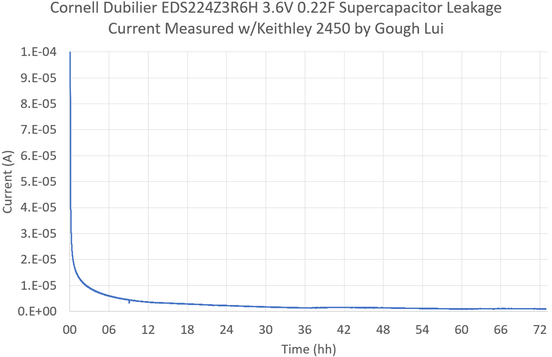
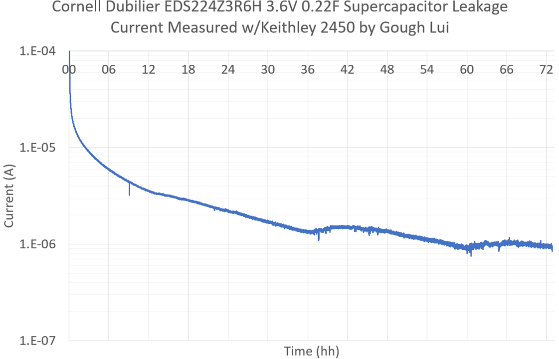
The current consumed by an EDS224Z3R6H as recorded by the SMU shows the reducing current as the capacitor charges over the 72-hour period. Some perturbation in the trend is seen due to uncontrolled room temperature variations. While the majority of the supercapacitor charges relatively quickly, the “long-tail” is visible, especially in this semi-log plot.
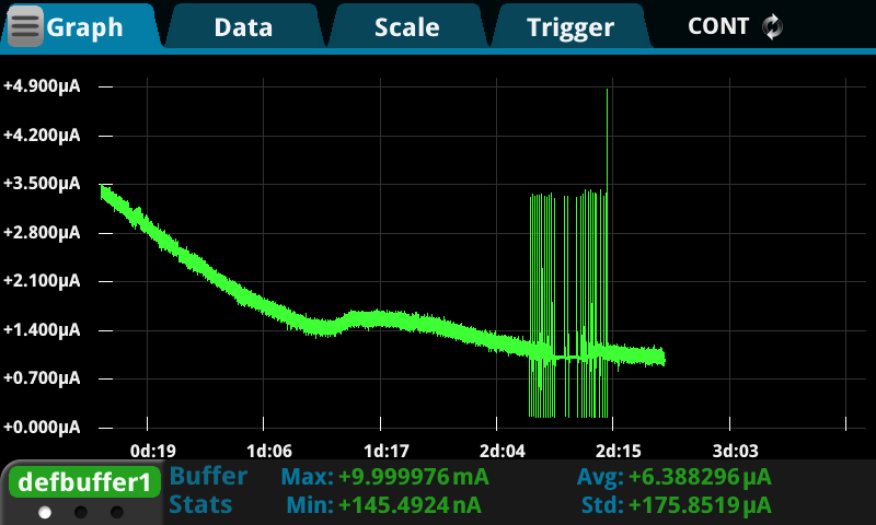
Note – I did not plot the result of the first SMU measurement as it had very unusual spikes towards the end of the test. The cause of these spikes were determined to be the auto-ranging behaviour of the KE2450 – when it decides to change range, it stops sourcing for a short period as the range is changed. Because of this discontinuity in voltage/current, the capacitor doesn’t resume charging at the same current and given enough time, the capacitor can cause the SMU to enter a nearly-continuous auto-ranging loop. Once I noticed this, I decided to manual-range the SMU at appropriate times and the problem (mostly) went away. This is one downside of SMUs where the sensing and sourcing are intimately linked.
Bonus: Handling Charged Supercapacitors
Now that I have a batch of charged supercapacitors, I can’t let them short out on one another. Unfortunately the sorter case we were provided doesn’t have enough slots for each capacitor to sit in its own slot. I’ve allocated the LICs each to their own, but EDLCs are all sharing, so I decided to fix this by dividing each box into two.
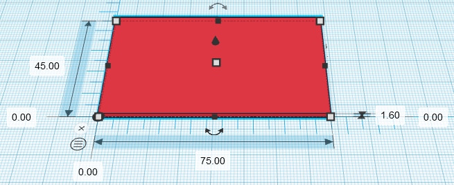
To do this, I designed a simple piece of flat plastic that would be inserted diagonally into each compartment to divide it into two. Going diagonal has the benefit that such an insert is self-supporting, won’t fall over and needs less material than a fully supported T-shape.
Thus, the solution is born and supercapacitors should short out no more … unless their legs are forcibly bent towards one another. Better than nothing, especially since I don’t have any styrofoam on hand.
You can download the STL file if you fancy printing your own: Sorter Divider.zip
How to Design a Supercapacitor Solution
Imagining that we now are comfortable with using supercapacitors in our designs, how can we find out which components will be suitable for our application? There are a few things to consider.
Load Profile
Generally speaking, supercapacitors are best suited for demands which are no shorter than 1-10s for pulse/peak-power applications depending on the type of supercapacitor. At the short end of the scale, the ESR limits peak currents achievable which can result in heating and limitations in lifetime. It would seem that radial types, larger cells and even multi-cell modules are much more suited to these types of applications. Shorter time-scales are better served by ordinary capacitors – e.g. filtering out mains ripple. Meanwhile, relatively low-current (mA) memory back-up applications can be serviced by coin-cell style EDLC supercapacitors which can be “trickled” in standby waiting for a power interruption.
Tolerable Voltage Window
Understanding the tolerable voltage window for your system is important to maximise the capacity use of the supercapacitor. The EDLC supercapacitors especially can operate up to 2.7V or 3.0V per cell (nominally) while their whole capacity depends on them being discharged down to zero. The LIC supercapacitors have a nominal 3.8V per cell voltage, but can only be discharged down to 2.5V or 2.2V.
The issue really is that the system that is connected to it likely cannot operate throughout this wide voltage window. For example, an ESP32 may operate between 3.0V (internal flash type) to 3.6V only. Using a linear regulator could extend the upper voltage range at the cost of quiescent current and power loss when the voltage is above the required voltage, while a switching converter may improve the tolerable voltage range by buck-boosting the supply at the cost of complexity and quiescent consumption. Simple implementations of supercapacitors may result in inefficient use of the available capacity owing to a limited window of voltage being useful.
Number in Series
Depending on the supercapacitor type in use, you’re likely going to need more than one in-series to get the necessary voltage for your load. In the case of an ESP32 that can operate at 3.6V, this would mean having two EDLCs in series, although a single LIC would do just fine as well.
While series capacitors add voltage ratings, the capacitance instead follows a 1/(1/C1+1/C2+…+1/Cn) relationship. Keep this in mind. Because of this, it may be necessary to have multiple series strings in parallel to meet your required capacity (more on this later).
But having more than one supercapacitor introduces a new complication – no two components are exactly identical. Because of differences in capacity, ESR and leakage rates, charging the series-connected capacitors with the same current will result in them being at slightly different voltages. If you had two 2.7V EDLC supercapacitors in series, it would be very unwise to try charging it to 5.4V exactly as one could be at 2.9V and the other could be at 2.5V especially at end-of-life when characteristics may diverge significantly. As a result, some balancing may be required.
Two classes of balancing circuit exist – passive balancing often just relies on having resistors which “waste” current in such a way that the unit with higher voltage suffers a greater draw that pulls down its voltage compared to the unit with lower voltage. Such a system, while simple, is often inefficient and only suitable where the current loss is acceptable. Active balancing relies on a circuit that uses the voltage to drive a transistor to shunt current around a supercapacitor that has reached its maximum voltage.
But a simple way around the whole balancing scenario is simply having enough headroom to accommodate the worst-case scenario. For example, with two 2.7V EDLC supercapacitors in series, if they were only charged to 3.6V total, this puts just 1.8V on each in the balanced state leaving a massive 0.9V of headroom. Depending on which source you read, 0.2V to 0.3V headroom may be sufficient to avoid the need to balance with well-made supercapacitors.
Load Current and Voltage Drop by ESR
In order to understand the capacity required and just how long you might get out of a given supercapacitor, it is necessary to understand the load current. For the ESP32 example, let’s imagine the unit is transmitting Wi-Fi in its slowest mode, consuming 240mA according to its datasheet.
We know based on I=C*dV/dt that dt =C*dV/I. Assuming a capacitance of 1F, going from 3.6V down to 3.0V, dV = 0.6V and I = 0.24A. Therefore, the expected hold-up time is 2.5 seconds for a 1F capacitor. This may not sound like much, but it’s a lot more than what you’d get out of a capacitor.
There is a wrinkle though … that is the theoretical ideal hold-up time. In reality, you get a sudden voltage droop as the load is placed on the supercapacitor due to its ESR. Assuming an ESR of 100mΩ, this droop will be 0.024V, reducing dV to 0.576V and the hold-up time to 2.4 seconds. The ESR will be entirely dependent on the model of supercapacitor used and is usually worse at end-of-life, so it may make sense to use 200% of the initial ESR rating for this calculation.
If you need more time, add more capacitance. But perhaps your system is lazy and operates at 3.3V and you have no convenient source of 3.6V to use. In that case, your dV is down to 0.3V in the ideal case and your hold-up time is just 1.25s in the ideal case. If you have an (ideal) lossless linear regulator and your supply is 5V, then you have expanded your dV to 2V and the same capacitance will give you a hold-up time of 8.3 seconds. Of course, these figures are made based on the pessimistic transmit-burst power – actual running current for the ESP32 on average is about half of this. This is why being able to fully utilise the voltage span of the supercapacitor is important to maximise its usable capacity.
The Issue of Lifetime
Having replaced many electrolytic capacitors in my time due to the capacitor plague, when I saw lifetimes stated of 1000h or 1500h at relatively low temperatures of 60°C to 85°C, this made me somewhat nervous about using supercapacitors. There are 8760 hours in a year after all. Furthermore, I knew from experience that any electrolytic capacitor worth its weight has a rating of 105°C and a load lifetime of usually 8000h+ for a quality unit. Nichicon ULDs now claim 10-20k hours at 105°C which is more than plenty!
Are the relatively low stated lifetimes and temperature ratings a problem in practice? I decided to approach this problem with reference to Cornell Dubilier’s guidance:


I went off to implement this algorithm in a spreadsheet when I realised … they never told us what n actually is!

As it turns out, n is a factor which denotes the sensitivity of the device to voltage. Not knowing the value, I set it to 1. Checking online for supercapacitor lifetime equations and guidance was very confusing, but I found another manufacturer (Jianghai) that has their own calculator for which the numbers match if n=1, so I had some level of confidence.
Using this, I was able to calculate the lifetime for all CDE supercapacitor series in this Design Challenge under various temperature and voltages. Cells shaded in dark grey are outside the operating window for that supercapacitor type, while cells shaded in light grey are acceptable but are extended above the test conditions or are surge-rated.
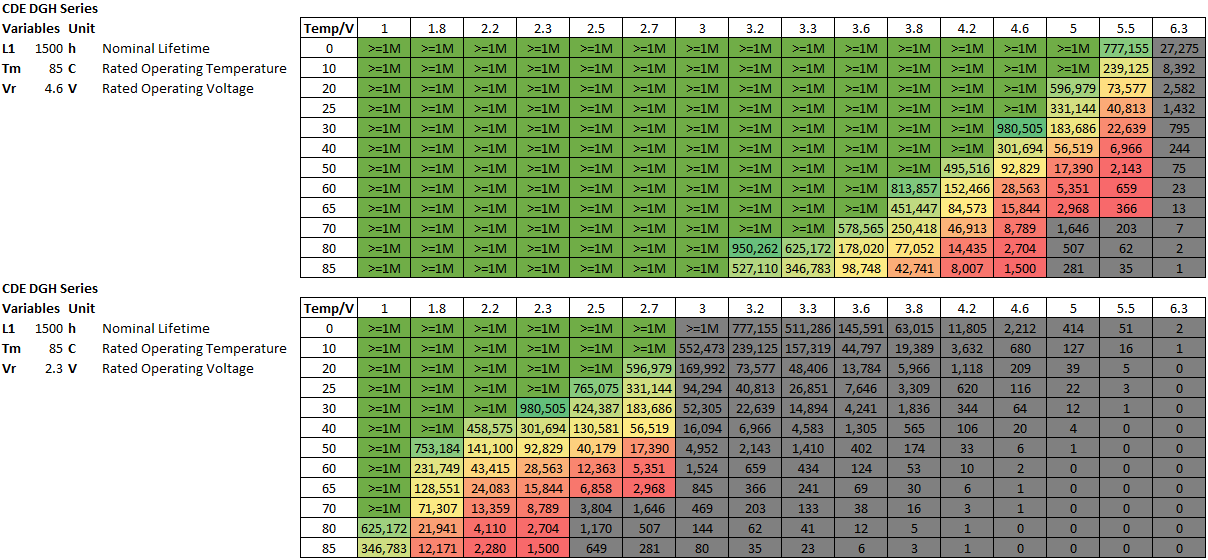
I truncated all results over one-million hours as that’s over 100 years and failure due to other causes is very likely. For the DGH series, there is a slight wrinkle – the nominal voltages at the test temperature are below the commonly stated 2.7V/5.5V values, so that is what is used. It seems that if it is used under room temperature conditions, use at the nominal rated voltage shouldn’t be an issue – the 5.5V part would last in excess of four years while the 2.7V part would last in excess of 37 years. However, if operation occurs inside a case, a computer case is commonly stated as 50°C, in which case a slight voltage derating would be recommended.

The DSF series shows a similar result, but because of its lower temperature rating, use inside a computer case may require a bit of derating from the 3V rating to 2.5V or so depending on the required lifetime.

The EDC series are higher-temperature units that claim long lifetimes and this is borne out in the modelling.

The EDS series are even higher-temperature long-lifetime units but with different voltage ranges. In this case, it is visible how these will operate well across higher temperatures at their rated voltage.
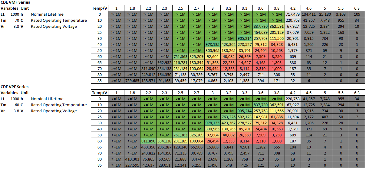
Comparatively, the LIC-based VMF and VPF series are somewhat more delicate due to the low temperature ratings. At room temperature, stepping back on voltage a touch would ensure a longer lifetime. In an enclosed condition with elevated temperatures, the voltage may have to be stepped back more significantly to 3.3-3.6V. Perhaps this is one of the downsides of LICs.
Overall, with some care, the lifetime can be managed through managing temperature and derating voltage. But this is not the only type of lifetime – there is also a cycle lifetime rating, but I’ll talk more about this in a future blog.

Reading the guide, however, it seems that lifetime can be cut-short by mishandling. One avenue is bending the leads too close to the base of the capacitor and putting stress on the capacitor bung itself which can affect the seal. This is something I’ve not paid so much attention to and have mostly gotten away with. However, knowing this now, I should probably avoid putting stress on the joints of all such radial cans, including regular wet aluminium electrolytic capacitors.
Bonus: Solar Panel I-V Curve
As I received the solar panel in time for the last blog, one thing that is still a bit of a mystery is its true specifications. As a result, I had to run some I-V curves to see what its performance is like. Unfortunately, my Keithley 2450 SourceMeter SMU was busy all week, so this time, I’m using my Rohde & Schwarz NGM202 two-quadrant PSU instead. In order to do this, I dug through my junk box for a 2.1mm x 5.5mm panel mount socket to use for connectivity.
My first characterisation attempt involved using a Neewer 40W high-CRI LED lighting panel normally used for videography. Pointing it down straight at the panel, I used the light-intensity sensor on my phone which claimed it was about 50,000 lux (although I don’t trust it). While this brightness would be about half that of AM 1.5 sunlight, the spectrum is strongly biased to the blue/yellow due to the use of LEDs and thus the output is not expected to be representative of solar operation.

Indeed, it was only able to turn up a measily 78mW maximum power under this condition, but it did show that the open circuit voltage was in excess of 5.5V which could endanger some supercapacitors. The fill factor appeared to be 76% which is fairly typical.
This was done simply by running an I-V curve script I had previously written:
# Basic IV Curve Tester

import pyvisa
import time

# Define Limits
maxvolts = 0
maxcurrent = 0.120

resource_manager = pyvisa.ResourceManager()
ins_ngm202 = resource_manager.open_resource("TCPIP0::xxx.xxx.xxx.xxx::INST0::INSTR")

# Roll Call
print("Available:" + "\n" + ins_ngm202.query("*IDN?"))

# Set Up NGM202
print("Setting Up - NGM202")
ins_ngm202.write("*RST")
ins_ngm202.write("INST:NSEL 1")
ins_ngm202.write("OUTP:MODE SINK")
ins_ngm202.write("SOUR:VOLT "+str(maxvolts))
ins_ngm202.write("SOUR:CURR 0.001")
ins_ngm202.write("SENS:VOLT:RANG:AUTO 1")
ins_ngm202.write("SENS:CURR:RANG:AUTO 1")

# Begin Voltage Experiment
print("Begin Testing")
input("Prepare for Test - Press Enter to Continue")
print("Opening a logfile ...")
data_log = "ivcurve-data.csv"
f = open(data_log,"a")
ins_ngm202.write("OUTP 1")
maxcurrval = int(maxcurrent*10000)
for x in range (10,maxcurrval,1):
  ins_ngm202.write("SOUR:CURR " + str(x/10000.0))
  time.sleep(0.1)
  read=0
  while read != 1 :
    try :
      ngvolt = ins_ngm202.query_ascii_values("MEAS:VOLT?")
      ngcurr = ins_ngm202.query_ascii_values("MEAS:CURR?")
    except :
      print("Retrying step " + str(x))
      time.sleep(1)
      continue
    else :
      read=1
  f.write(str(ngvolt[0])+","+str(ngcurr[0])+"\n")
  f.flush()
  print("Completed step " + str(x))
ins_ngm202.write("OUTP 0")
f.close()

# Announce Completion
print("Script Completed!")
ins_ngm202.close()
Because of the poor result, I had no choice but to consult the sun on a sunny day …
I took the power supply outside and sat it in the backyard on a chair with the panel propped up on a medicine box. Hooking it into power was all that was absolutely necessary, as the NGM202 has on-board 2.4GHz Wi-Fi for network-connected SCPI commanding. Unfortunately, the signal was a bit weak, so the program stalled every-so-often. The sun shining on the instrument was also not a good idea – this can lead to temperature excursions outside the operating window and may also affect the instrument’s calibration. Nevertheless, I wrote a robust variant of the first code which just continually swept and retried while I left the power supply outside in the sun for two hours either side of noon. In the future, it would probably be better just to use the logging feature and EasyArb to continually sweep and record to USB locally on the NGM202, rather than suffering the delays of remote commanding.

The returned data was noisy – this is not unexpected as birds, clouds, the motion of the sun and other obstructions cause the light received by the panel to be inconsistent. Interestingly, a lensing effect can occur with clouds where solar intensity dips but also rises under certain circumstances. Taking the average was not sufficient (in red), but the eyes can make out what the trend is and ultimately, it seems the panel does meet the specifications assuming it is Voc and Isc. Estimated actual maximum power is around 432mW at 4.55V/95mA with a fill factor of just 70%, so expecting to run a 5V device off this alone, reliably, is not likely unless you can stay below 70mA. All this is good to know for when I actually come to use the panel.
Conclusion
Leakage is an important parameter to pay attention to, as it betrays the health of a capacitors’ internals and also indicates the potential power lost within the capacitor which may be critical in energy harvesting or low-rate long-back-up scenarios. Because of the long time-constant of supercapacitors in general, leakage tests are performed with a 72h settling time which is time intensive. A simplified method using a power supply, resistor and digital multimeter is much more accessible than using a source-measure unit for the whole exercise.
All of the Cornell Dubilier supercapacitors measured well with leakage, well below the specification levels even for most of the damaged LIC types. It was so low that reading noise was difficult to separate from the result, but indicates good initial manufacturing quality that should translate into good lifetime.
I’ve walked through a simple process to size and understand the up-time that a supercapacitor can provide to a system, while also examining the issue of lifetime from manufacturer’s data using a modelling equation. While the lifetime figures for supercapacitors are quite a bit less than the lifetimes stated for leading aluminium electrolytic capacitors, depending on the operating condition, sufficient lifetimes can still be achieved especially with reductions in operating temperature and operating voltage.
I’ve also managed to characterise the supplied solar module, under indoor LED illumination and outside under bright mid-day sun in Sydney. The solar panel appears to have a maximum power of about 0.432W at 4.55V/95mA with a 5V output requiring a load under 70mA under good sun. Open-circuit voltage exceeded 5.5V, thus some supercapacitors may be at risk under no-load conditions.
Of course, there is still plenty more to learn about supercapacitors. While I’ve touched upon the lifetime aspect, there is another lifetime that might need to be considered and that is cycle life. In the next posting, I hope to explore a little about temperature effects from a practical perspective and put supercapacitors through some abusive torture in the name of science.
[[What’s Super about Supercapacitors: Blog Index]]
- What’s Super about Supercapacitors? – Part 1: Me and the Kit
- What’s Super about Supercapacitors? – Part 2: Types, Vendors, Safety & Specifications
- What’s Super about Supercapacitors? – Part 3: Measuring Capacitance & ESR
- What’s Super about Supercapacitors? – Part 4: Measuring Leakage, Sizing a Solution & Lifetime
- What’s Super about Supercapacitors? – Part 5: Safety Under Abuse & Power Back-Up Application
- What’s Super about Supercapacitors? – Part 6: Solar LoRaWAN PM Sensor, Low-Temps, Imbalance, Cyclic & Short Circuit Life, LED Blinker
- What’s Super about Supercapacitors? – Part 7: Quite a lot, actually! (Final)

