After looking at leakage current measurements, sizing a supercapacitor solution, supercapacitor lifetime and plotting the solar panel I-V curve, this forth “extra credit” blog will look at safety aspects related to supercapacitors. Specifically – how do they handle abusive conditions such as reverse polarity and over-voltage? Furthermore, I’ll be looking at the “magic” behind the 5.5V EDLCs and modify a kit I have to use them as the source of power back-up. This will be an exciting post, with some thermal video for all to enjoy.
Table of Contents
What’s Inside a Supercapacitor?
As a child, I grew up building kits on my own and one caution that was often repeated was to ensure that electrolytic capacitors were placed in the correct orientation. As a polarised component, I figured that they wouldn’t work if installed backwards. It wasn’t until freshman year in university did I understand the consequences of reverse-polarity on some units, as some pranksters had the bright idea to “correct” their friends’ breadboard constructions to deliberately elicit smoke and explosions. This was potentially dangerous – one could easily get aluminium can shrapnel in the eye, but who knows what was in the electrolyte that gave the smoke an “acrid electronics smell”. It’s also entrained within me, a caution of anything that could potentially be a pressure vessel.
Before proceeding, I should reiterate that experiments performed in this section ARE potentially dangerous and should not be attempted. If you choose to do so, you do it at your own risk which may include bodily harm. I have taken precautions to limit the risk and have performed these experiments in the name of learning more about supercapacitors.
Part of that safety is to understand what is inside a supercapacitor, just in case it comes flying out (or you choose to take one apart). As supercapacitors are finished components intended for integration into other products with no safety issues under normal handling and they’re usually not likely to be ingested, finding such information can be difficult.
In the end, I was able to identify the following Material Safety DataSheets (MSDS) from various manufacturers with different formulations of product:
I did not find any for CDE’s products or hybrid LICs in particular, but I have little reason to believe they would be substantially different.
Key ingredients aggregated across all MSDSes include:
- Activated Carbon (15-35%)
- Carbon Black (0-12%)
- Paper/Cellulose (2-12%)
- Aluminium (25-50%)
- Propylene Carbonate
- Tetraethylammonium tetrafluoroborate (5-35%)*
- Acetonitrile (5-40%)*
- Proprietary Cyano-substituted Hydrocarbon*
- Proprietary Hydrocarbon Substituted Nitrogen*
Items marked with * are potentially of concern, with exposure limits and are known to be toxic, cause irritation or are flammable. The first italics entry appears to be related to the plastic casing used in Cooper Bussman’s PM-series supercapacitors. The latter two in italics seem to be uncommon and are proprietary to the Ioxus MSDS. The remainder appears to be consistent across datasheets.
Some further research on acetonitrile suggests that it is mildly toxic due to being metabolised into hydrogen cyanide after a delay of up to 12 hours but poisoning is rare with an LD50 oral of 2460mg/kg. Because of the proportion in the supercapacitors and the size of the capacitor, this is not a major concern. Tetraethylammonium tetrafluoroborate is a little more mysterious, however, as it is both listed as an irritant and causing acute toxicity, but data on exposure limits appears to be lacking.
As a result, it’s probably not a good idea to breathe in any fumes generated … although that’s probably common-sense anyhow.
Experiment #4: Reverse Polarity
Supercapacitors, being polarised components, should always be used in line with their indicated polarity. That being said, during my early research, I discovered that the structure of an ELDC is symmetrical which theoretically would mean that reverse polarity would not damage the EDLC. Indeed, one manufacturer also claimed in their datasheet that minor reverse-polarity up to 2.3V didn’t cause harm in their tests but would not guarantee this as the EDLC was formed in one polarity at the factory. I also discovered that LICs were asymmetrical with their configuration and seemed unlikely to tolerate reverse polarity. Seeing we already had some over-discharged LICs, I wondered how they would fail.
To test this, I used the slow 1mA/F capacitor testing script in the previous part with my Keithley 2450 SourceMeter to measure the capacitance, but in reverse for three cycles, then forward-biased for three cycles. I also measured the AC ESR using the B&K Precision BA6010 to ascertain if there were major differences. I did this for a 2.7V EDLC, 3V EDLC and 3.8V LIC.
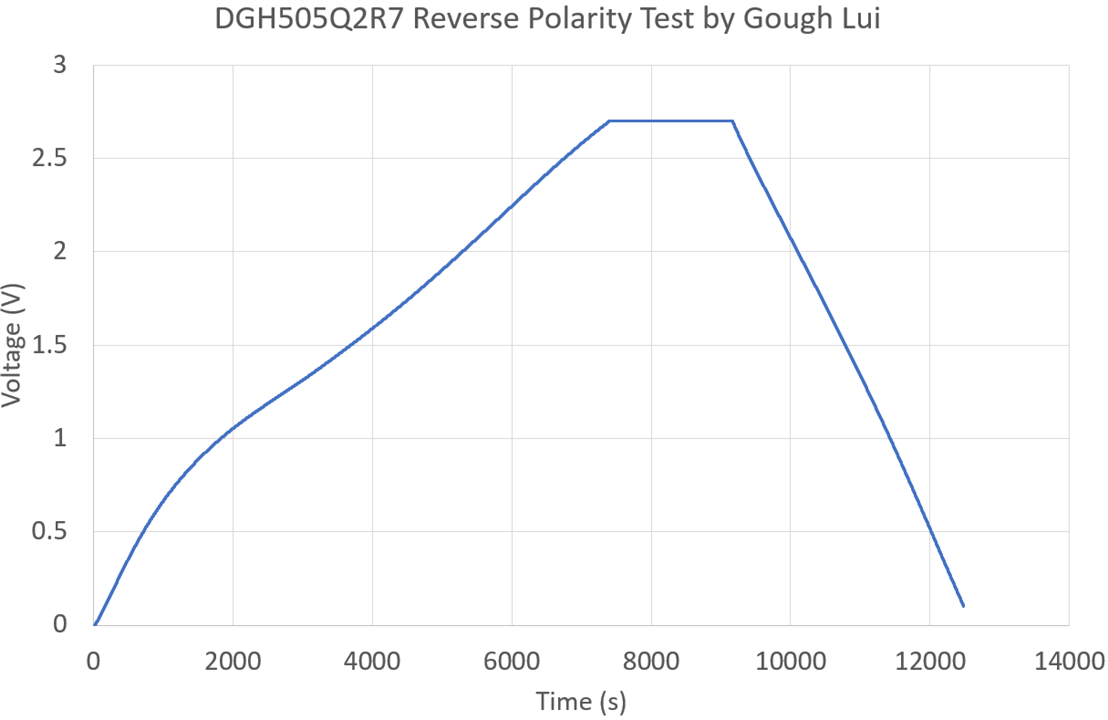
Rather unsurprisingly, the information about the EDLCs seems to be true – a slight non-linearity is seen at the low voltages, but the charging and discharging was successful with the 2.7V EDLC (DGH505Q2R7).
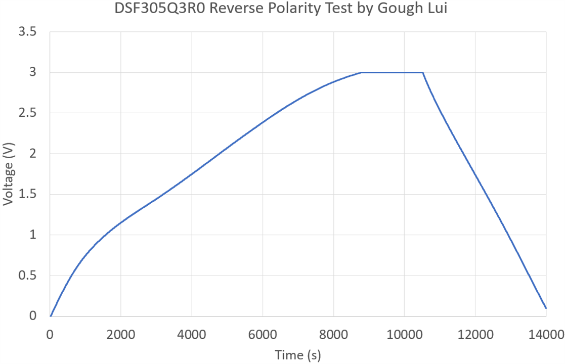
Testing with the 3.0V rated EDLC (DSF305Q3R0) shows much the same trend, although perhaps there’s a bit more of a non-linearity towards the 3V part as well.
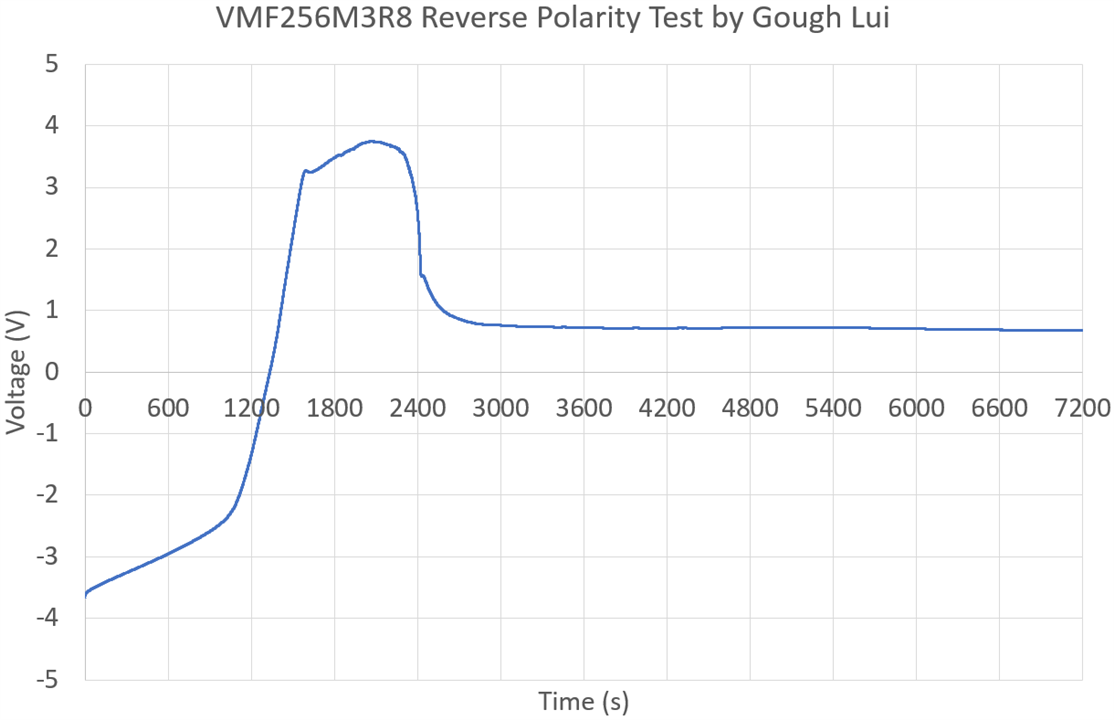
The LIC (VMF256M3R8) tested did not survive the reverse-polarity treatment. In fact, the script could not be aborted while saving the data, so a second LIC had to be sacrificed in this test. Of note is that both were over-discharged and recovered prior to the test, so they may not be representative of stress-free LICs. Nevertheless, the discharge from charged state is relatively linear until hitting about 2.4V when it rapidly accelerated to a new slope. This slope extended until about 3.2V in reverse when some breakdown might have occurred, flattening the curve and turning it around after some time to a soft-shorted condition.
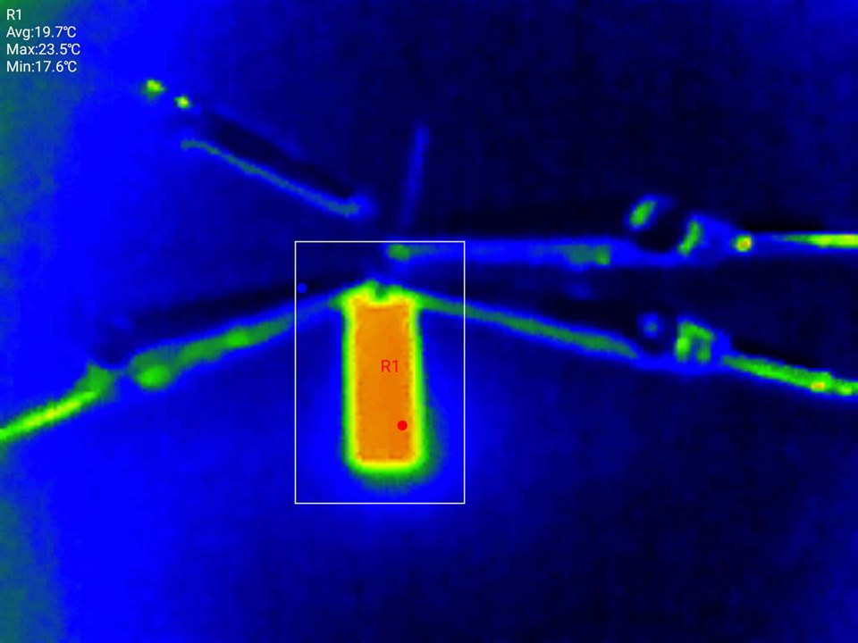
The capacitor was only seen to warm-up ever so slightly compared to background temperature throughout this process, never reaching any dangerous temperature.

Applying forward current did not recover the capacitor’s function, even after an hour, resulting in a capacitor that was soft-shorted in both directions. Of note is that under such conditions, the capacitor showed no external signs of distress as power dissipation was quite limited. Under high-current conditions, this may not be the case.

Looking at the measured capacitance, it seems that the EDLC parts survived practically unscathed in terms of capacitance. The AC ESR figures seems to have gone either way by a small amount – in no way are the parts unserviceable although their long-term safety could still be under question. The LICs both soft-shorted internally and were no longer capacitors after the first reverse-polarity excursion. The AC ESR figures both showed increases – one approximately doubling which would usually indicate end-of-life, but are otherwise inconclusive.
As a result, it seems LICs cannot tolerate accidental reverse-polarity as over-discharge leads to a slope change at 2.4V, then some sort of breakdown seems to happen around -3.2V resulting in a soft-shorted condition. Under current-limited test scenarios, there was no externally visible distress although higher-current supplies could lead to a more significant outcome. However, the two tested EDLCs didn’t show any permanent damage as part of the reverse-polarity experiment although long-term safety and reliability is inconclusive. This suggests the symmetry of the structure internally makes them somewhat reversible.
Experiment #5: Overvoltage
Now that I have a few abused and potentially unreliable supercapacitors, what should I do with them? Another potential abuse condition with safety implications is overvoltage. Shall we see what happens when we exceed the rated voltage? I’m sure you can guess …

This test was performed outside for safety reasons. Unlike the previous test, I used the Rohde & Schwarz HMC8043 power supply. Initially starting off with just one channel, I concluded my tests by paralleling all three channels together for more current. Rather than using Wi-Fi connectivity, for reliability, I used a 30m Ethernet lead for remote control (which arrived just this week).

Thick outdoor terracotta tiles were used as a test surface with a clear thermal signature. Thermal imaging was recorded with my Nokia G60 5G connected with the Xinfrared InfiRay P2 Pro USB-C thermal camera. The phone was attached to a tripod thanks to this 3D print design by neyfrota. A second tripod was positioned with a DSLR camera providing the visible video (not in picture, as being used to take the photo).
The results were quite varied – the EDLC only had a minor venting …
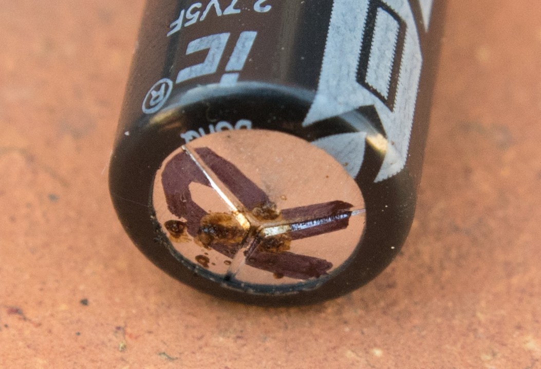
… with one LIC showing a more significant venting with a lot of smoke. Leaving the voltage applied allowed the whole thing to essentially “cremate” itself.
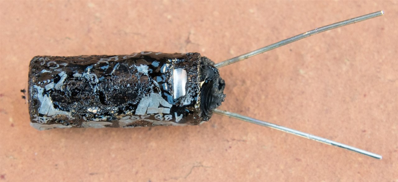
The final LIC …

… went full-on explosive. That is definitely a possibility with every component in a can, when the pressure builds much quicker than the vent can release (or if the vent fails to blister).

I call this meal “deconstructed supercapacitor, sans aluminium shell”. The bung and leads are visible with the connections to the foil. Pieces of paper, carbonised copper are also visible. The spiral construction appears very reminiscent of ordinary aluminium electrolytic capacitors.
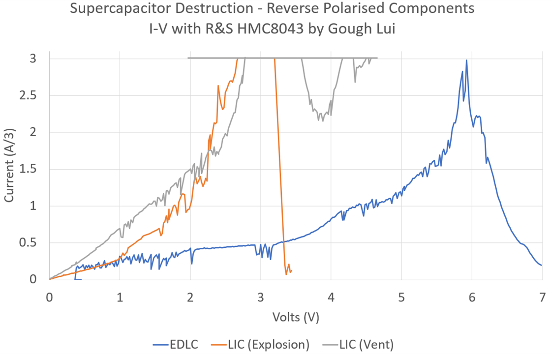
Looking at the I-V curve, it seems the current begins to take off around 3.5V for EDLCs. The LICs were both soft-shorted, so it was more like dissipating power into a resistor – but interesting to see both showed rather similar curves. Note that this is measurement only from Channel 1 of the power supply with a 3A capability, but as three channels were commanded in parallel, the actual current delivered is 3x the indicated number. Another thing is the “noise” in the plot is due to the channels “fighting” one another to deliver the current – this is not unusual.
I did want to see what would happen to a coin-cell type EDLC as I suspected it would fail around the seals given a lack of a vent, but the last experiment happened to be quite loud and my neighbours were just starting up a housewarming event. I didn’t want to cause any trouble … or get myself into trouble … so I’ll call it quits while I’m ahead.
What’s in a 5.5V EDLC?
One question I’ve had ever since I received the kit is whether such a thing as a 5.5V supercapacitor cell actually exists. It’s a common voltage rating for memory backup applications … but not in other form factors.
Cutting back the sheathing on some of them gives us the answer …

Turns out the EDC105Z5R5H (5.5V 1F) supercapacitor is made of two cells in series. In theory, this could be two 2.7V cells (5.4V) but that seems a bit close, so perhaps two 3V cells (6V) would be more likely. These must be well-matched cells that are quite stable, given that there is no balancing. I think this is good confirmatory evidence that balancing may not always be required.
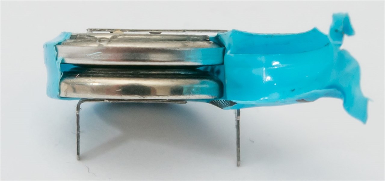
Even the EDS224Z3R6H (3.6V 0.22F) supercapacitor is made of two cells in series. In that case, two 2.7V cells are enough – but perhaps this construction with such under-rating of voltage helps to produce longer service lifetimes.
But there are also PCB-pin mount cans like the EDS104Z5R5C (5.5V 0.1F) that don’t have an obvious ridge under the heatshrink to suggest they are two cells in series.
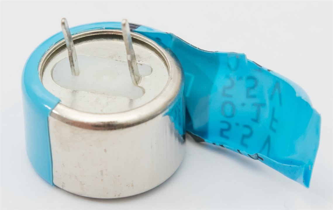
In fact, cutting away the heatshrink reveals a smooth-sided can. But I wasn’t so easily defeated … so I got out my side-cutters and started to nibble at the seam.
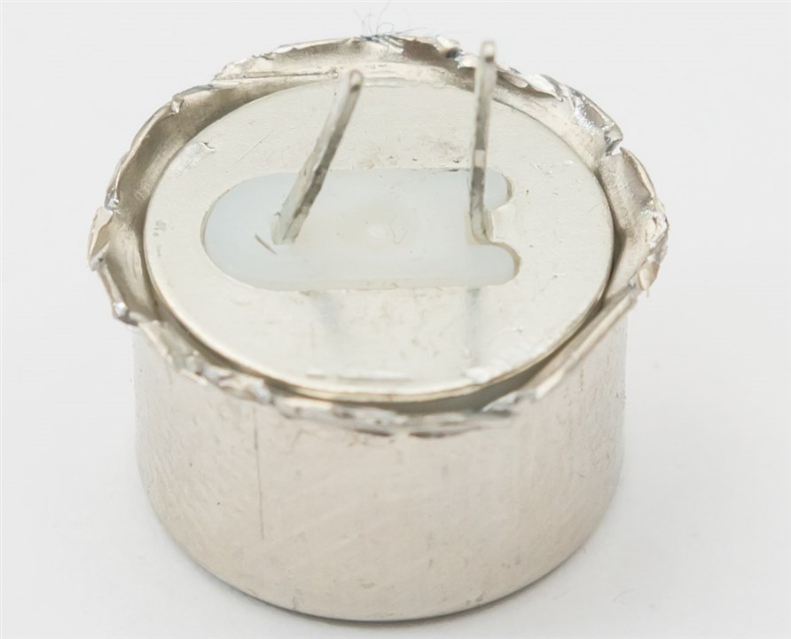
With a bit of a tug, the contents “sproinged” out onto my desk.
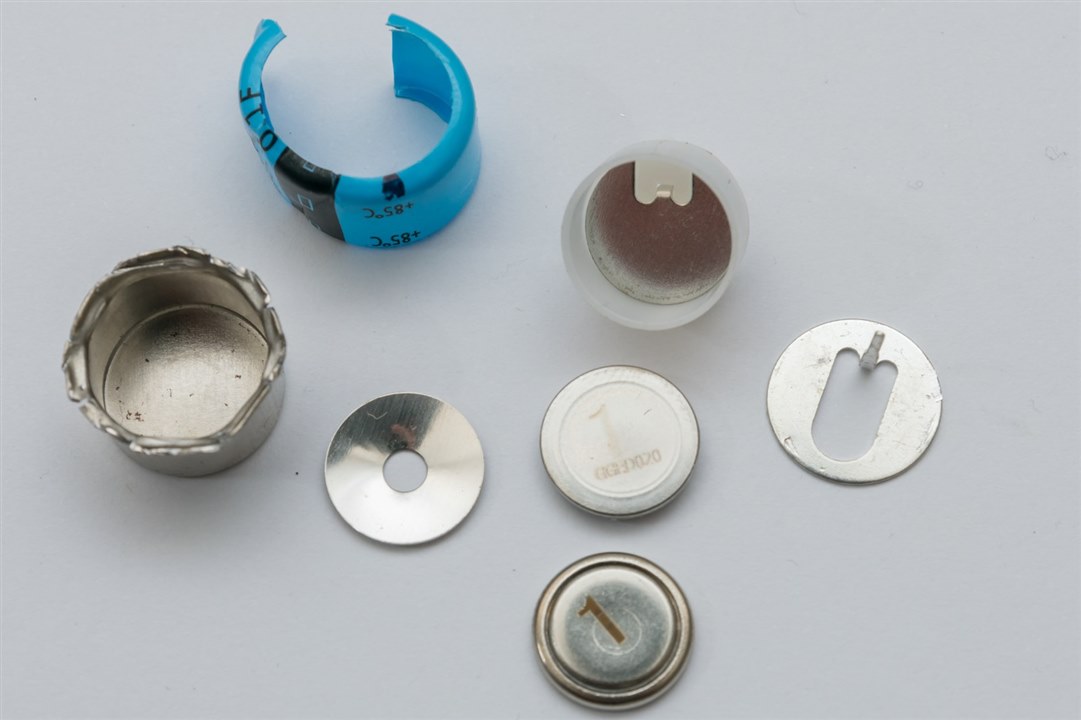
As it turns out – the metal can is just a mechanism to hold two supercapacitor coin-cells together in series by a “spring” disc applying pressure to the stack. The can forms one side of the cell, while the inner contact in the plastic insulating sleeve forms the other. The form may be different, having loose laser-marked cells (probably for matching) but functionally it is equivalent to the welded forms above. I consider this mystery solved!
Experiment #6: Power Loss Backup
What good is experimenting with supercapacitors if I don’t get to put them into use? As part of my recent RoadTest on the Weller WXsmart Soldering Platform, I constructed this clock kit that featured a CR2032 cell holder for power back-up.
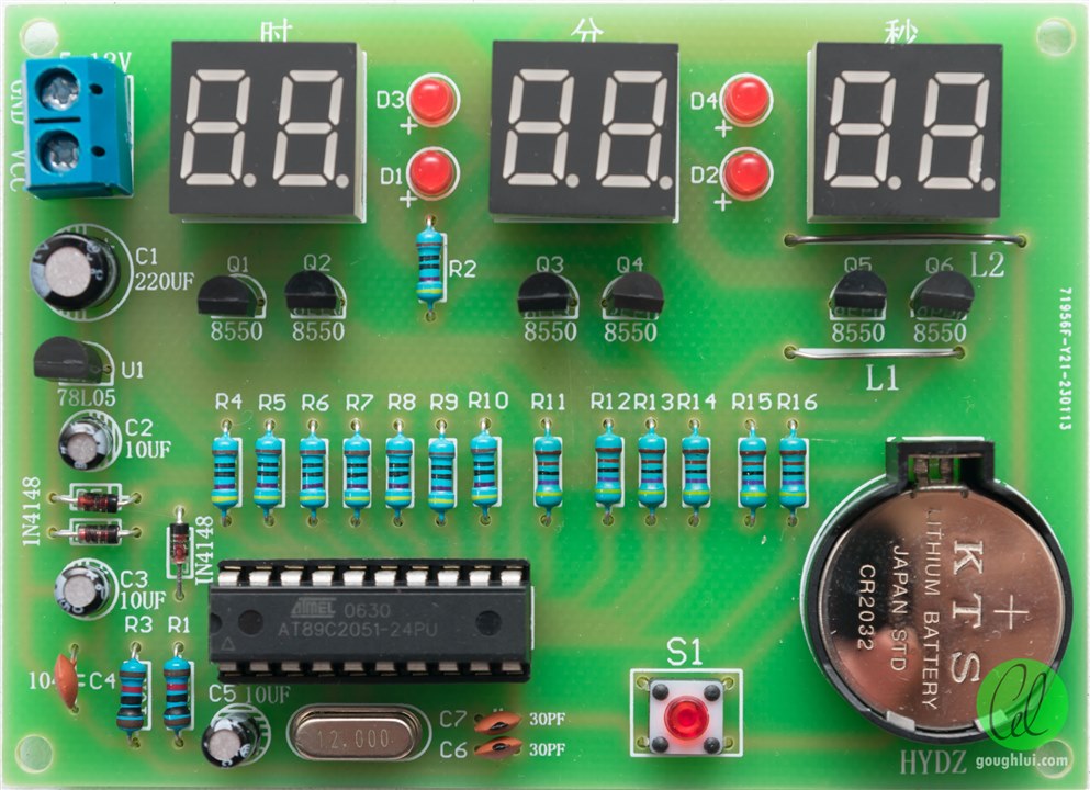
After blogging about this, I received a comment that the design of the kit seems like it was geared towards the use of an LIR2032 (lithium-rechargeable) coin-cell rather than a disposable one and that it wasn’t safe as it was to use it with a CR2032 cell. I also found the CR2032 back-up to only last a fairly short time as well, likely as this kit isn’t really using an RTC but instead using the cell to keep the whole microcontroller running.
To understand the tolerance of this input to various voltages and to understand the current consumption, I used my Keithley 2450 SourceMeter to provide input to the CR2032 coin-cell input while the kit was being powered by the Rohde & Schwarz HMC8043.
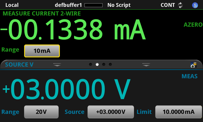
While the kit is powered, about 134µA of charging current is going into the SMU thanks to R1.
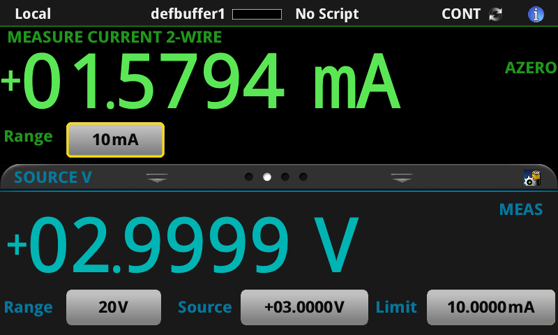
When the kit is unpowered, the microcontroller is taking a rather sizeable 1.58mA from the cell at 3V. This is because this is not a true RTC but it is instead powering a running microcontroller.
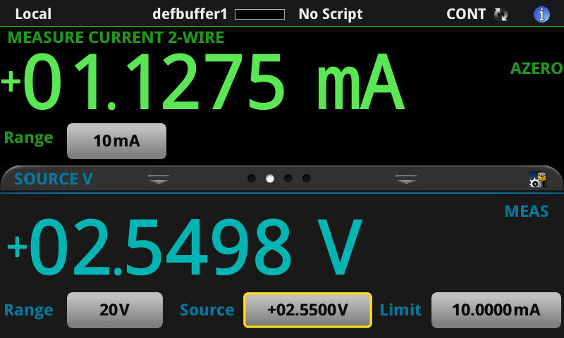
When the voltage drops to about 2.55V, the current falls slightly to 1.13mA, but any lower and the microcontroller loses its state and time, suggesting this is the low-point.

At the worst-case input of 5V, the current consumed is an astronomical 5.03mA. This suggests that the benefit we get from charging above 3V is very likely to be diminished because of increasing current consumption.
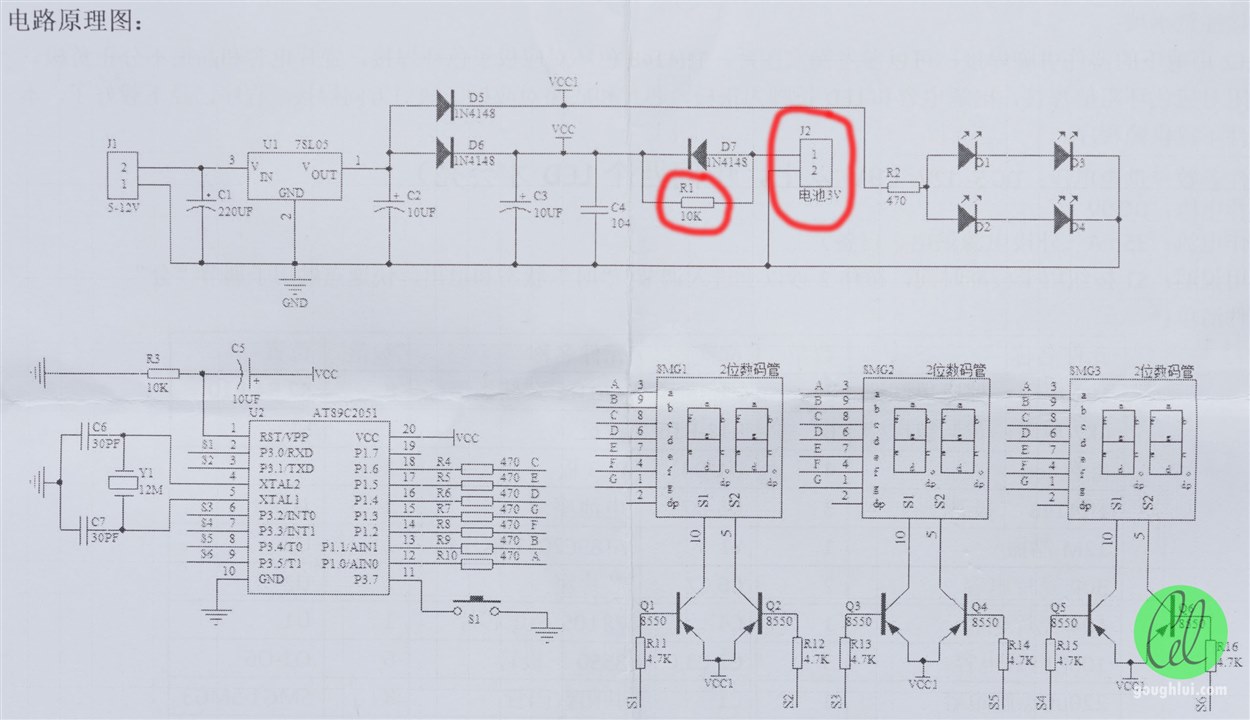
Looking carefully at the schematic, it seems clear that the battery is being trickled through R1 (10kΩ) which is a bad idea if it is a primary cell. But this suggests we can easily modify this for supercapacitor usage. To do this, I decided to simply remove the battery holder and change R1 to 47Ω to allow the cell to charge more quickly without overloading the 78L05 regulator. However, because of the design, there are a number of 1N4148 diode drops which limit the supercapacitor charging to about 4.38V and will waste some voltage when under supercapacitor use. To remedy this, it may be desirable to replace D6 and D7 with higher-current Schottky diodes to reduce voltage drop, but I didn’t have any on-hand.
Based on this, if I choose the 5.5V 1F supercapacitor and run from 4.38V down to 2.55V based on an average current of 3.08mA, then the expected up-time is (dV = 1.83V, I = 0.00308) is 594 seconds or 9 minutes and 54 seconds excluding any voltage droop considerations. This may not seem long compared to the months-to-years of an RTC-based solution, but keep in mind that this is running a whole microcontroller, then this is quite a good result. Definitely enough time to change power sources or to relocate the clock without losing time.
To its credit, the pin-spacing of the EDC105Z5R5H part matched the PCB CR2032 holder perfectly for a neat modification.
In practice, after permitting one hour of “soak” charging of the supercapacitor, the back-up time to 2.55V was 11 minutes and the time was maintained correctly. This is pretty close to estimates – likely because actual current as the voltage varied was not well accounted for.
Experiment #7: Cyclic Current Torture (In Progress)
In the previous blog, I talked a bit about the lifetime of supercapacitors versus temperature and applied voltage. While that is a very traditional way of looking at lifetime and seems to suggest that if we manage temperature and voltage appropriately, we can obtain sufficient lifetimes; supercapacitors are often used in cyclic applications such as in transportation for kinetic energy recovery or in sensors and radio applications for buffering power for each transmit burst.
Because of this, there is another lifetime which is defined by the datasheet which is cycle life. For Cornell Dubilier’s DGH series supercapacitor, a cycle is defined as a charge to working voltage for 20s, CV charge for 10s, discharge to half of working voltage for 20s, rest for 10s, all at 25°C. For the VMF/VPF LICs, this is only defined as a charge/discharge from 3.8V to 2.5V at 25°C. Typically claimed cycle life is in the 250,000 to 500,000 cycle region.
Based on this, the lifetime of a supercapacitor operated at the 1-minute cycle is up to 500,000 minutes or about 347 days. Unfortunately, I don’t have this time to do such a test.
Furthermore, I had neglected to also consider the effect of internal ESR in the temperature-based lifetime. Keep in mind that while it is often said to the “ambient temperature”, it should really be the temperature of the capacitor and self-heating can be significant.
For cycle-life torture, I decided to take a different approach and shorten the test a bit while also making it even more torturous. Using my Rohde & Schwarz NGM202 two-quadrant power supply and my self-designed banana to terminal adapter, I connected two DGH105Q2R7 (2.7V 1.0F) to the power supply, one to each channel.
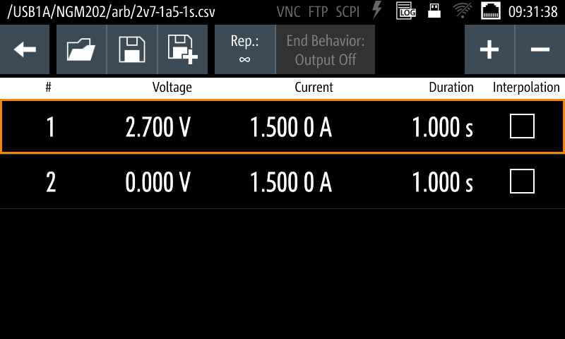
Using the internal QuickArb feature, I made a cycle comprising of 1s charging and 1s discharging in a loop. The left channel was set to 0.96A (the maximum 1s-current as stated by the datasheet). The right channel started off at 3A (the maximum the NGM202 could source and sink).
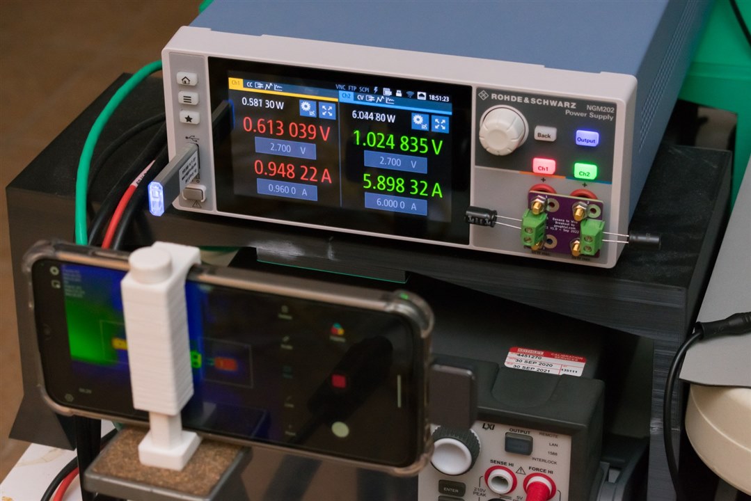
The torture began at 27/08/2023 18:04 (UTC+10). Observing the thermals with the Xinfrared InfiRay P2 Pro thermal camera revealed the following:
Under the rated 1s-current, the left capacitor rose to 36.5°C in a 21°C ambient, a 15.5°C temperature rise. Pushing the current up to 3A (which is below the short-circuit rated current) resulted in significantly more heat generation – reaching 132.5°C within eight minutes leading me to abort this test to avoid the potential for capacitor venting. I really don’t want to have my bedroom being filled with supercapacitor smoke … so instead, I cut the current down to 1.5A instead which keeps the capacitor at a toasty 85°C and restarted the test. But even considering the fact that the capacitor may be rated at 1,500 hours at such temperatures, it would take 62.5 days to reach the “time” lifetime which is time I don’t have.
Based on the 2s cycle time, 43,200 cycles can be completed in a day and the 500,000 cycle rating will be exhausted in 11.5 days. While this wouldn’t be consistent with the manufacturer’s test regime, I’m hoping that this will demonstrate how a supercapacitor might age when subjected to cyclic loads, but it is difficult to predict. This test is ongoing and the results should be reported in the next extra-credit blog.
Conclusion
In this blog, I was able to look up various MSDSes to learn about what is inside a supercapacitor. While most ingredients are inert, there are a couple that are known to be flammable, toxic and irritating. It’s pretty common sense that one shouldn’t breathe in any such fumes, especially those which may result from abuse.
That being said, it seems EDLCs are indeed “symmetrical” in their internals, despite the polarity markings, as my tested units seemed to survive reverse polarity with no measurable adverse effects. That is not to say that there are not any reliability or safety impacts. The LICs being asymmetrical did not survive, soft-shorting as something appeared to happen at around -3.2V.
Overvoltage abuse results in heating, increase in pressure and gas generation which can cause venting or explosion. It seems the one EDLC was relatively mild while the two shorted LICs showed more severe venting right up to explosion. Not wanting to anger the neighbours, I did no further experiments of this type.
Looking at 5.5V EDLC supercapacitors, it turns out that all of these seem to be made of coin/button-style cells. The ones with pins underneath are just enclosed in a can which serves to connect the two cells together. All of these are likely to be well-matched at the factory and do not have any balancing. Even the 3.6V EDLC appears to be made of two cells.
I was able to modify a 7-segment LED clock kit to replace a CR2032 battery backup with a 5.5V 1F supercapacitor and demonstrate successful power backup for the microcontroller over a period of 11 minutes which was fairly close to calculations.
Finally, I was also able to commence on a cycle-life torture test which is accelerated compared to the manufacturer’s definition of cycle. Self-heating effects were rediscovered as they will have impacts on capacitor life beyond just ambient temperature. Using a current approximately three times higher than the 1s-rated current caused drastic self-heating which resulted in the capacitor reaching 132.5°C within eight minutes.
In the next (and final) extra-credit blog, I hope to present the results of this cycle-life torture test while also looking another application of supercapacitors – this time, hopefully involving the solar panel. I may also look at the behaviour of supercapacitors under a short circuit and cold temperatures, if the time permits. This has been a lot more work than I expected …
[[What’s Super about Supercapacitors: Blog Index]]
- What’s Super about Supercapacitors? – Part 1: Me and the Kit
- What’s Super about Supercapacitors? – Part 2: Types, Vendors, Safety & Specifications
- What’s Super about Supercapacitors? – Part 3: Measuring Capacitance & ESR
- What’s Super about Supercapacitors? – Part 4: Measuring Leakage, Sizing a Solution & Lifetime
- What’s Super about Supercapacitors? – Part 5: Safety Under Abuse & Power Back-Up Application
- What’s Super about Supercapacitors? – Part 6: Solar LoRaWAN PM Sensor, Low-Temps, Imbalance, Cyclic & Short Circuit Life, LED Blinker
- What’s Super about Supercapacitors? – Part 7: Quite a lot, actually! (Final)

