I didn’t realise when I published my last “extra credit” blog that it would fall on a national holiday weekend in the US. As a result, some of you may have missed some rather interesting experiments looking at safety under abusive conditions and my first application in power back-up. If you haven’t read that posting, you really should as you can watch some rather interesting thermal video and get some background to some of the experiments being presented in this instalment.
As part of the new “design challenge” rules, this post will be my final “extra credit” blog. It comes a few days prior to the deadline and is the fifth in the series of “extra credit” blogs. This massive posting will cover cyclic current torture, short-circuit torture, application in the form of a solar-powered LoRaWAN particulate monitoring system, an exploration into series-connected supercapacitor voltage imbalance, performance at low-temperatures and implementation of a basic LIC-based supercapacitor LED blinker.
Table of Contents
- Experiment #7: Cyclic Current Torture (Continued …)
- Experiment #8: Short-Circuit Torture
- Experiment #9: Solar-Powered LoRaWAN Particulate Monitor Sensor
- Experiment #10: Series-Connected Supercapacitor Imbalance?
- Experiment #11: Performance at Low Temperatures
- Experiment #12: LIC Supercapacitor LED Blinker
- Conclusion
- Obituary: Lenovo ThinkPad Edge E431
Experiment #7: Cyclic Current Torture (Continued …)
I commenced the cyclic current torture experiment in the previous posting detailing my attempt to determine the effects of cycling on supercapacitor characteristics through a shortened test protocol as I didn’t have the 347-days it would otherwise take.
My initial tests involved two DGH105Q2R7 2.7V 1.0F EDLC supercapacitors undergoing a 1s-charge/1s-discharge protocol at two pre-set current limits.
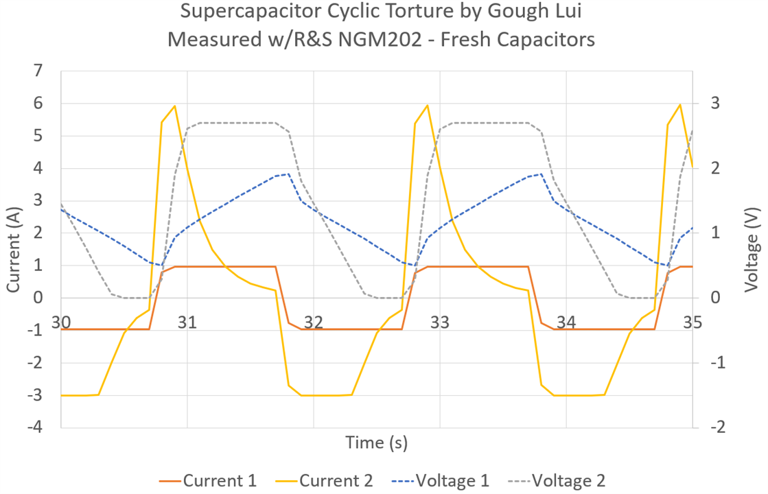
Initially, I was quite enthusiastic with #1 running at the 0.94A 1s-current rating and #2 running at 6A charge/3A discharge (at the limit of what the Rohde & Schwarz NGM202 power supply can do). With fresh capacitors, we can see that both capacitors easily reach the current limit at least for some portion of the charge. Sample #1 however doesn’t fully charge nor discharge at this current limit, so it “breathes” happily banging between positive and negative current limit.
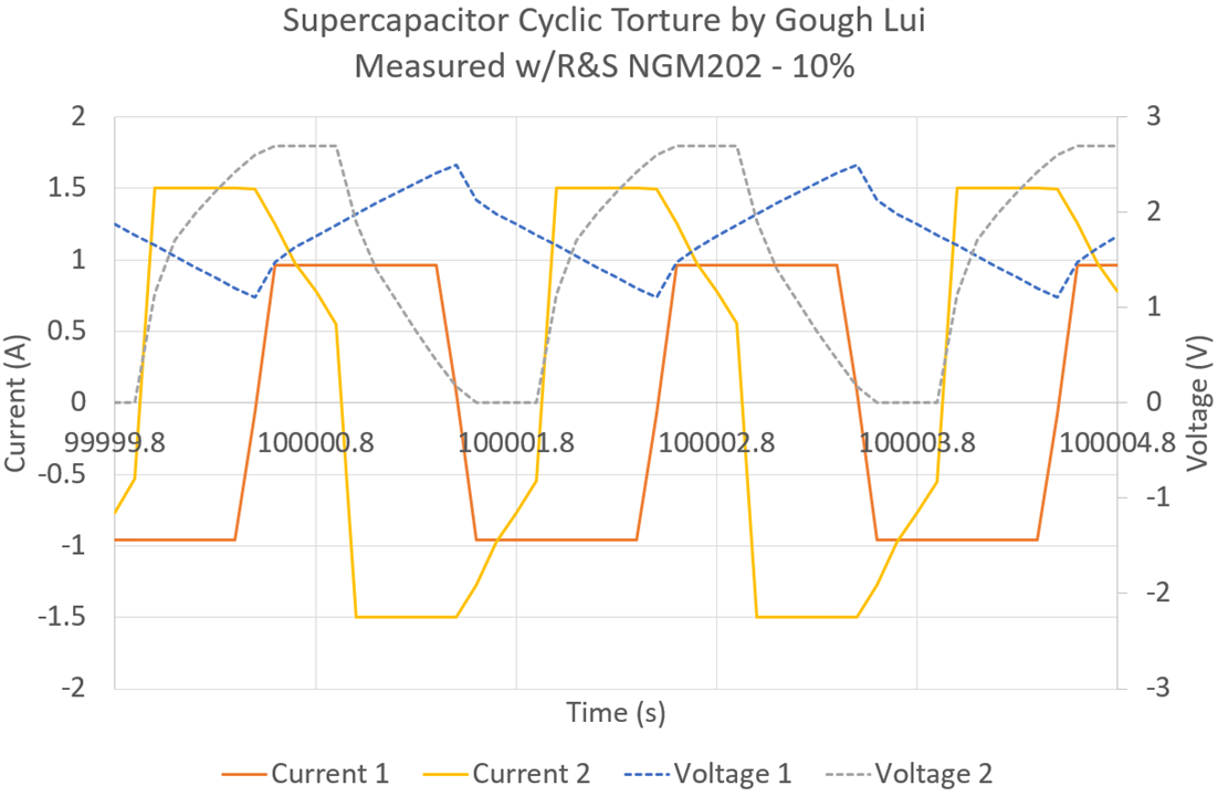
Around 10% in the test time, I have had to reduce sample #2 to 1.5A limit because temperature was reaching critical (likely-to-vent) levels above 130°C. With this decreased current level, it seems the capacitors is mostly (60%) constant-current charging or discharging.
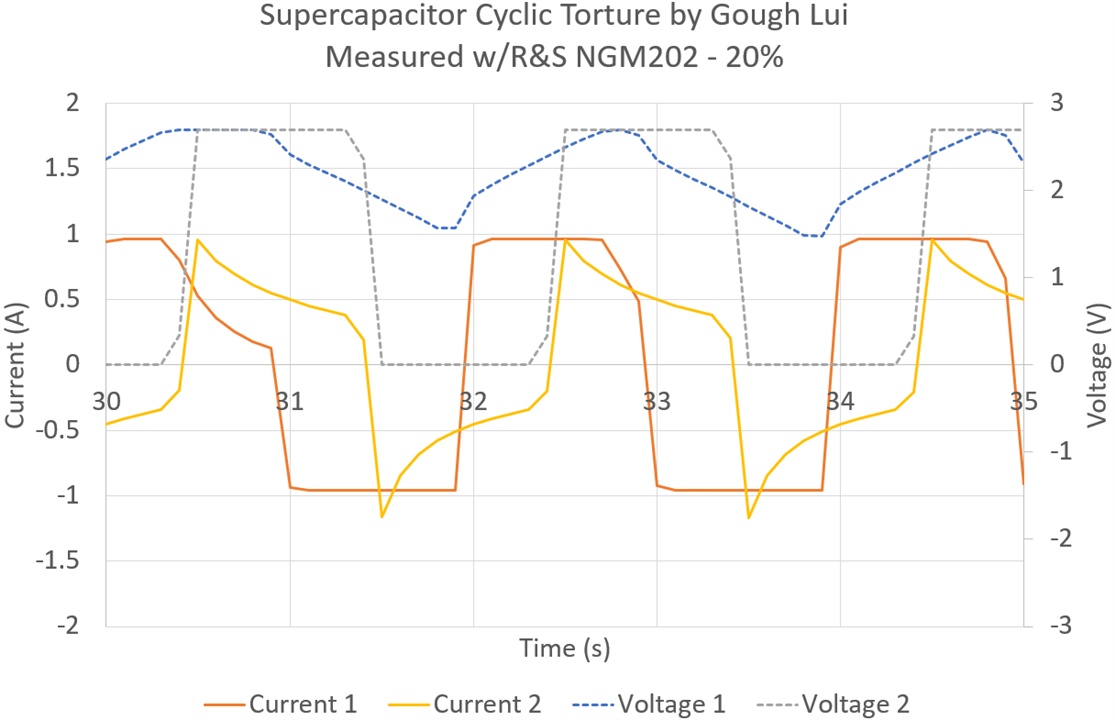
By 20% of the test time (ignoring the time scale as this is for each log file), sample #2 can not sustain even the 1s-current rating, suggesting an increase in ESR beyond specifications. Sample #1 continues to perform as expected, although possibly due to temperature/leakage/test-equipment effects, the voltage is now reaching the upper-limit suggesting charging is more efficient than discharge.
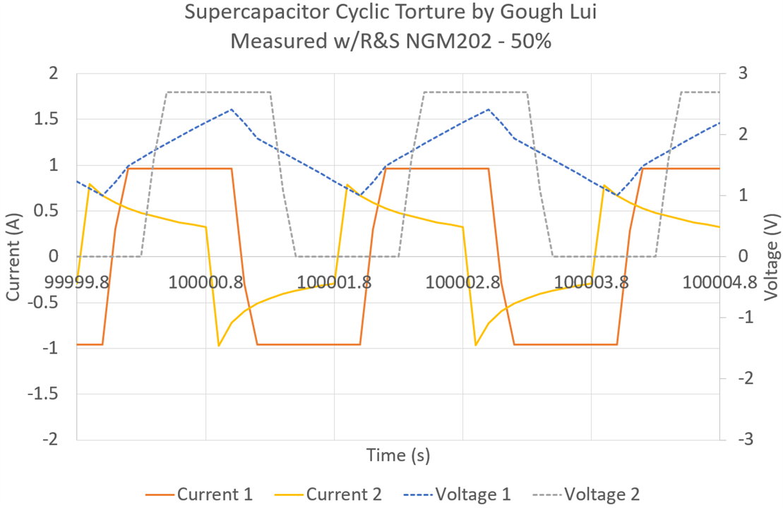
At 50% of the test time elapsed, sample #2 is taken offline shortly after this reading is taken. The current sustained by sample #2 is now well below that of sample #1. Sample #1 has now reduced in voltage slightly which brings it back to “breathing” away from the voltage limits.
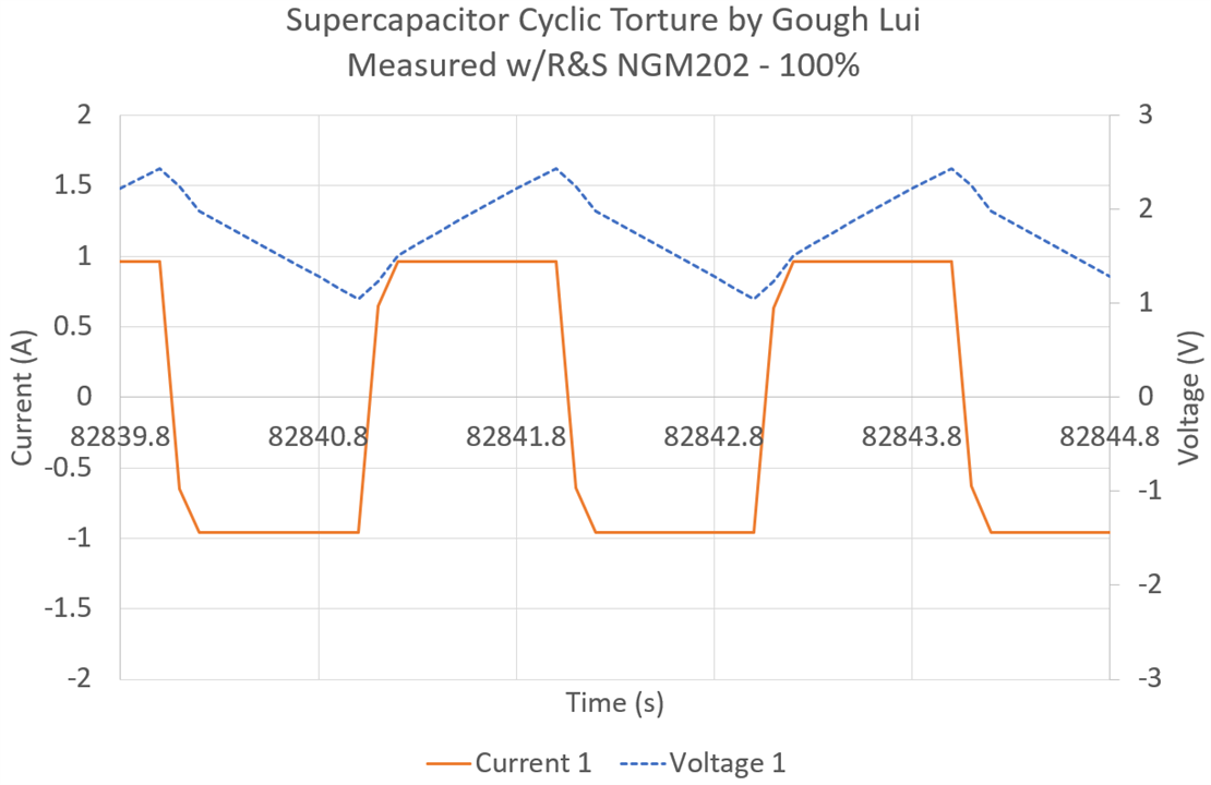
At the end of the test, shortly before sample #1 is taken offline for leakage tests (due to time limits), we are approaching 476,880 cycles and the supercapacitor still is working well at constant-current in both directions suggesting ESR within specifications. This impresses just how important it is to respect the specification limits regarding currents if you want to have the rated lifetime.
Of course, I felt that this was not sufficient. While it was seen that exceeding the 1A-rated current was devastating to the ESR of one of the supercapacitors, resulting in its rather swift demise, I also wanted to know what would happen under more extreme circumstances.
Experiment #8: Short-Circuit Torture
In most documentation I’ve seen, there are warnings not to short-circuit supercapacitors. However, in some applications where supercapacitors are used, high peak currents are a key characteristic and the temptation may exist to abuse them at near-short-circuit conditions. After all, datasheets do list short-circuit current … but is it wise to try this?
For this experiment, I had to build myself a quick rig that could safely short-circuit capacitors.
Ferreting around my junk box, I found a very basic 9V DPDT relay from Tianbo that was rated at 16A that I wouldn’t otherwise have a use for. The 16A rating is a little wimpy compared to the supercapacitor’s short-circuit current rating, but paralleling the two contacts should help with the current carrying issue (but perhaps not contact wear because the contacts won’t have identical timings). Nevertheless, I used short lengths of 16AWG silicone wire to carry the current while providing a back-EMF protection diode at the coil which was then connected to two 24AWG lengths of silicone wiring to “activate” the short using a second channel on the Rohde & Schwarz HMC8043 power supply.
To make my life easier, I crimped some 4mm bullet receptacles which I use with banana leads from the first channel to charge the capacitor. Bussing the connections together are three-way Wago 221-series connectors. I also set-up my smartphone with an Xinfrared InfiRay P2 Pro thermal camera to observe the set-up in case dangerous temperatures were being developed.
A simple script toggled between charging and shorting on a time-basis. Capacitors of different types were tested although no LICs were tested as they are not allowed to be bought down to 0V. Test candidates were DGH505Q2R7 (2.7V 5F Radial), DSF305Q3R0 (3V 3F Radial), EDC105Z5R5H (5.5V 1F Coin).
As the coin type had reflective surfaces, I put a square of black electrical tape on the surface to get more accurate thermal imaging results.
The results are quite interesting – in the thermal video below, the effect on short circuit on heating of the legs is clearly visible as a cyclic pulsation (3s charge, 2s discharge for radial, 17s charge, 3s discharge for coin):
However, it seems that such torture is quite difficult on the supercapacitors and clear changes in characteristics occur relatively quickly. In around 6,852 cycles, DGH505Q2R7 managed to swell and dome its vent.
In just 45 cycles, close monitoring of DSF305Q3R0 was able to detect significant differences in the charging characteristic which suggested ESR increase. For this test, I actually fitted a Holdpeak HP-605C current clamp around the lead to the relay and used the Rohde & Schwarz MXO4 (under review) to measure the short circuit current -
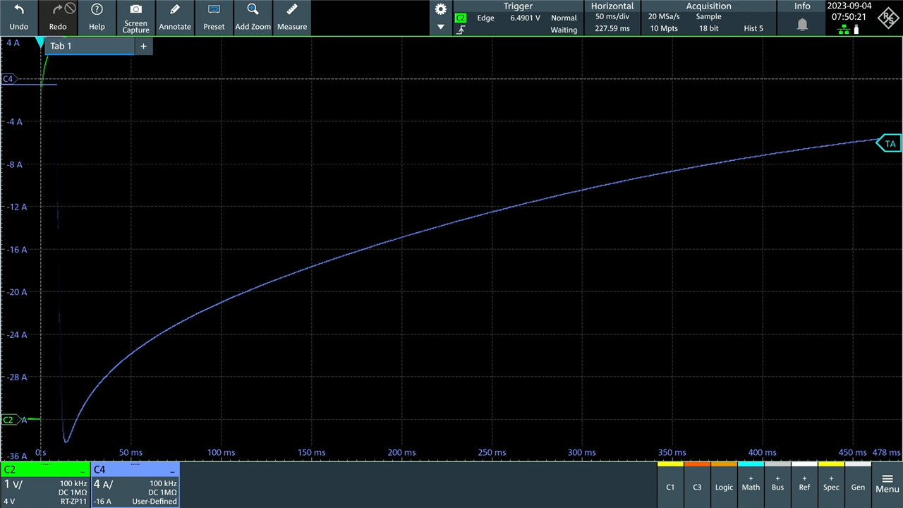
Initially, around 35A short circuit current was observed, but just five cycles later …
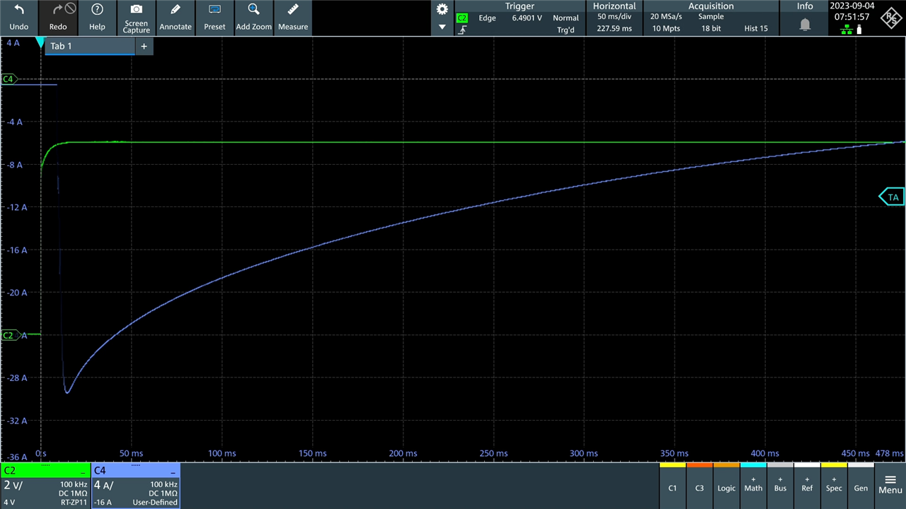
… it fell to about 29.5A. This could be a temperature-related effect or an actual ageing effect – but as the previous tests ran for excessive numbers of cycles, I terminated this one earlier to see if the effects occur even after a modest number of short-circuits. Notably this is still significantly higher than the datasheet claimed short-circuit current of 20A.
However, cyclic shorting of EDC105Z5R5H on a slower cycle managed over 13,000 cycles without any noticeable change in characteristics. This may be because of its intrinsically higher internal resistance being protective by limiting peak current and associated temperature rises.
The aggregate results for both cyclic current and cyclic short-circuit torture is summarised below:
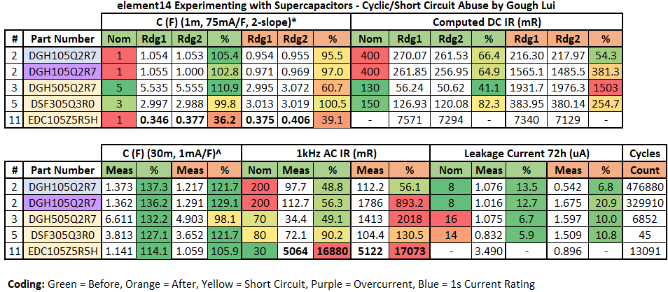
This table required a lot of time to compile, in part because the full suite of tests needed to be re-run to understand if any characteristic changes resulted from the torture. The key changes visible in end-of-life supercapacitors include a drastic increase of DC internal resistance to above twice nominal values and AC internal resistance increases. That being said, it seems the DGH105Q2R7 that was operated within its 1s current ratings survived 476,880 cycles (close to the 500,000 cycle rating) without significant change in characteristics aside from a small reduction in effective capacitance within its ratings.
Leakage currents were interesting – the supercapacitor cycled within its 1s-current ratings actually improved its leakage by almost half. The coin-cell supercapacitor subjected to cyclic shorts also improved its leakage by over three-fold. This phenomenon is not unheard of with supercapacitors, as they may improve their leakage over their initial readings. The others, however, showed an increase of about 50% in leakage current.
Experiment #9: Solar-Powered LoRaWAN Particulate Monitor Sensor
At last, we come to the application which I proposed that would make use of the included supercapacitors and small solar panel. Building upon my design from the Save the Bees Design Challenge which runs quite well from lithium-ion rechargeable cells, I wanted to take the batteries and large solar panel out of the equation and replace them with the supercapacitors and small solar panel. Such a set-up would be space-saving but might also last longer as battery cycle life and tolerance for extremes is quite limited. The downside is that there won’t be any operation without sunlight …
Ideally, if I were to properly design a system to maximise use of solar power for a sensor application, I might consider implementation of maximum power-point tracking on the solar panel to maximise power generation. I would also have a very low quiescent switching converter with a wide input voltage to generate stable output for the sensor to avoid voltage-related errors and increase the usable voltage range of the supercapacitor. I might also have a power supervisor to generate a power-good signal to avoid the microcontroller from powering up without sufficient charge or to hold it in reset when the charge dips below an acceptable level. It might also have a voltage-window for use with LICs to avoid over-discharging them as well. Because of the voltage required, it will require two supercapacitors in series, so an active balancing circuit might be nice too.
However, there isn’t really the time to source and design such a complex solution, so I opted to go simple and see if it would work sufficiently well.
As the system is based around the Arduino MKR WAN 1310, power is handled by a BQ24195L. Looking at the datasheet, this solution can handle an absolute maximum of 6V on its battery input, even though it is designed for a lithium-ion battery of up to 4.2V when charging. As I won’t be using the BQ24195L to charge, this won’t be an issue and the solar panel’s 5.7V open-circuit voltage is within the capability which is nice.
To charge the supercapacitors, I’ll be using the solar panel. While I could connect it directly to the power bus, the solar panel was measured to have about 300µA leakage when it has a lower voltage than the bus. This “dark current” is a known phenomenon related to the quality of the cells and to prevent it, it is customary to use a low-leakage diode. I used a 1N4004 in-series with the solar input, which has the side effect of bringing the input voltage down to around 5.05V. There was no need for any current-limiting resistances for the supercapacitors, as the solar panel is a current-limited source well-within the limits of the supercapacitors chosen.
For power storage, I decided to settle on using two 3V 7F supercapacitors (DSF705Q3R0) in series to give a 6V 3.5F-equivalent supercapacitor. As I won’t be using any balancing, I discharged all capacitors and kept the leads shorted for an hour to ensure they were “empty” before commencing. With an expected 5.05V maximum, there should be enough headroom to operate without balancing.
The next thing to be concerned about is what happens when the voltage falls down as the supercapacitors discharge. The BQ24195 used by the MKR WAN 1310 is designed to keep the lithium-ion battery safe from overdischarge, so it should be stable down to that voltage. Unfortunately, below this, we cannot operate and the energy in the supercapacitors cannot be used. Another thing to think about is whether the unit will wake-up when voltage is applied, as it could be non-monotonic and unstable. Apparently, the datasheet claims that it will come up as long as the voltage rises above VBAT_DEPL which is 2.4V typical + 0.17V hysteresis. As a result, it will come back to life if the “battery” (ahem, supercapacitor) is externally charged outside of the BQ24195. Within the operating range, the BQ24195 keeps the Arduino’s internal voltage rail stable at 3.8V which is then linearly cut down to 3.3V for the microcontroller.
In many ways, because of the behaviour of the BQ24195 is the saviour here, making such a simple modification possible –
However, there are still issues to contend with – radio transmissions require quite a bit of power and so there is a risk that the unit can “come up” without sufficient power to complete a transaction, resulting in wasted airtime with the unit repeatedly making incomplete transmissions and maybe even resetting in a loop. As a result, I modified the code to measure the voltage from a 1k/1k2 voltage divider to determine if there is enough charge to commence. The modified code with a 5-minute transmit cycle is below:
Prior to putting this into action, I checked the current consumption behaviour with the Keithley 2450 SourceMeter –
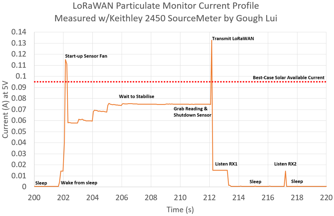
While I did previous work to try and minimise the current to keep batteries lasting longer, we can see that the current peaks well-exceed the 95mA best-case power from the solar panel. This would cause a serious brown-out on the rail which is likely to result in the unit resetting before it could get any work done.
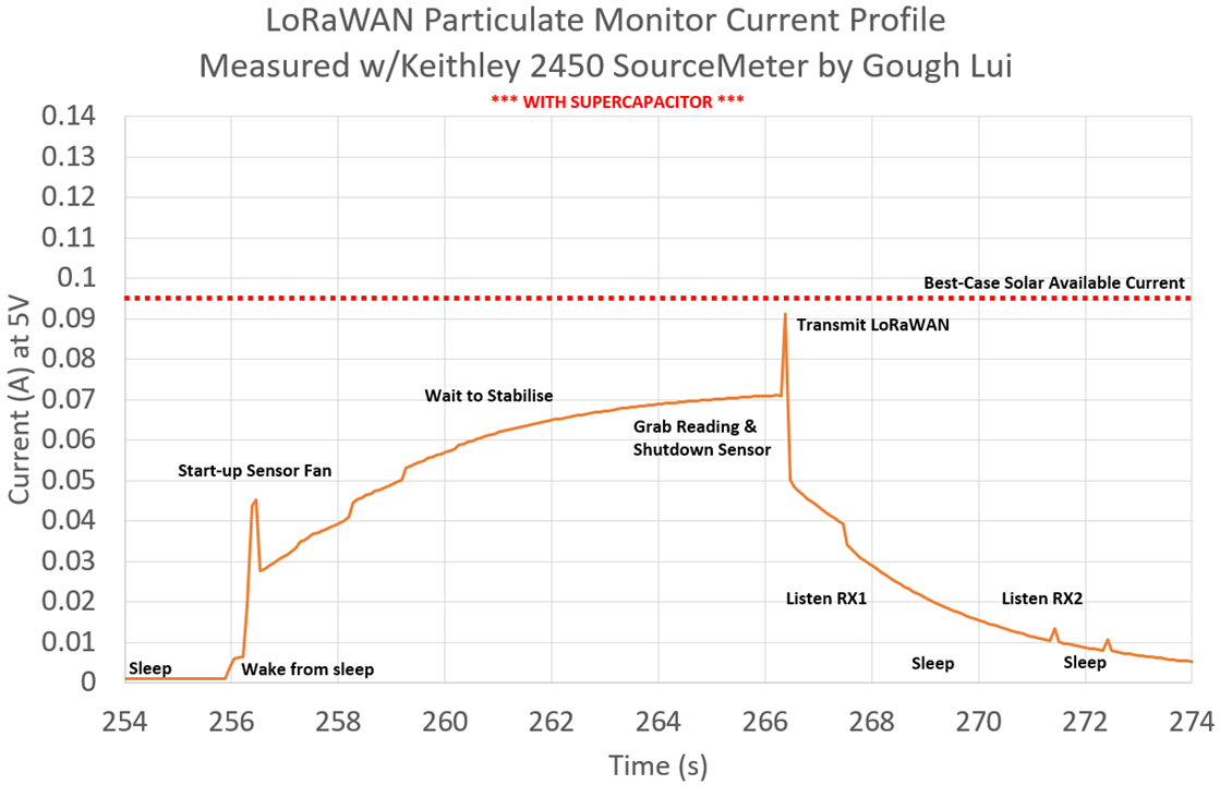
Just installing the supercapacitors and having the SMU enforce a fixed voltage, we can now clearly see that we are below the 95mA threshold, as it uses up the stored power in the supercapacitor to service the larger peaks and takes current to charge the supercapacitor when the system isn’t drawing as heavily. Of course, in reality, the difference is much more drastic as the voltage rails are allowed to swing a little and the supercapacitors will ensure they don’t suddenly collapse under load. So in reality, one can perhaps still operate with a current-limited supply that has closer to the full-cycle average current.
Nevertheless, assuming we need about 75mA for 12s and 0.878mA for 300s of sleep for a transmit cycle, how long will our supercapacitor solution last? Each transmission cycle requires 5.817J of energy, while the supercapacitors will hold 11.83J from (5.0V down to 2.4V) so it has enough energy on a full charge to handle two transmission cycles. This means that clouds are not a big issue for us!
So outside it goes – under a protective canopy of a plastic tubs weighed down by terracotta tiles.
The catch-22 of particulate monitor sensors – they have to be exposed to air to get good readings, but this could lead to them being exposed to liquids which could kill it. While I didn’t expect it, we had two days of very strong winds and a day of rain too …
… but the system lived!
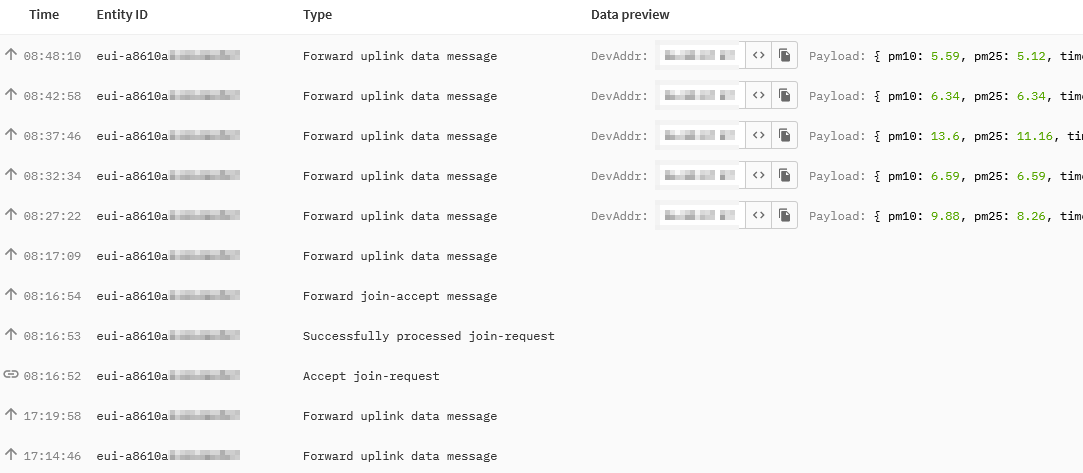
Every morning, I am watching The Things Network to see my device join the network and start transmitting messages. Often it will join under weak sun, then inhibit a few transmissions as it waits for its supercapacitor to charge back up. But just like the Mars Rover, my probe is “phoning home” whenever it can!

Looking at the bus voltage, considering I’m using low-quality 5% carbon resistors which might drift in the sun, it’s quite clear that most days, we’re able to get a pretty stable voltage in the sunny part of the day. The key outlier is 8th September which was a cloudy and rainy morning, hence the scatter and the fact it woke up later that day. Some cloud-lensing effects are likely too, explaining the voltage increasing above the level of clear days.
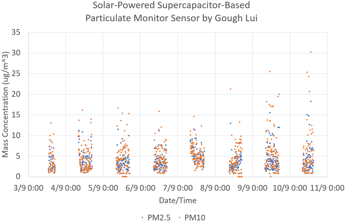
We get a nice scatter of PM values – of course, the use of a sensor like this is potentially problematic as it may reset before it ever gets to self-clean. But it’s clear that there are some trends – 7th September was a day where some backburning occurred, and the cluster is slightly elevated. Today, 10th September, is also a planned backburning day too – some of the higher PM10 points may correlate with “wisps” of smoke flying by in an otherwise clear day.
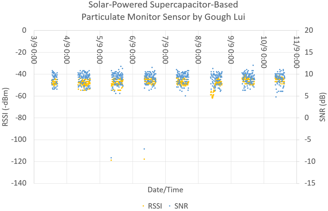
The radio-metrics also seem rather normal for the most part – a slight dip in RSSI on 8th maybe due to atmospheric attenuation, while outliers on 5th and 6th are likely due to collisions with other transmissions. Otherwise, the transmissions sit around 5-12dB SNR and around -50dBm RSSI.
Experiment #10: Series-Connected Supercapacitor Imbalance?
In the previous application, I made the assumption that no balancing was necessary based on the headroom in voltage ratings and what I had read in other application notes. But was this actually the case? Let’s first start with a practical experiment.
I chose to run this experiment on two DGH106Q2R7 (2.7V 10F) and two DSF256Q3R0 (3.0V 25F) supercapacitors as they were the only radial supercapacitor pairs I had that were not otherwise occupied. The capacitors were discharged and then shorted for an hour.
Then, using jumper wires, I configured them in series and then applied 5V at 1A to the set for four hours. Afterwards, the voltage was disconnected and the voltage across each capacitor was measured using a Keithley 2110 5.5-digit DMM. The results are presented below:

It seems that the first pair might not have been as close as the numbers suggested – they had a difference of 130.1mV between the two capacitors. The second pair was much closer, having just 2.5mV difference between the pairs even though the test figures didn’t seem to suggest that they would be that close. From this practical experiment, it seems that the amount of headroom required is in the order of a few hundred millivolts.
But let’s take a more mathematical approach of worst-cases. For a hypothetical radial supercapacitor of 1F, given +/- 20% tolerance, one may be 0.8F while the other is 1.2F. If we put the two in series and apply 5V, what happens? If we take Q=CV, in the ideal case where capacitors share charge equally, Q=2.5C. Based on this, we can work out the voltages each would be expected to reach given this amount of charge – 2V for the 1.2F capacitor and 3V for the 0.8F capacitor – a discrepancy of 1V. If this was a 3V capacitor, then might appear just acceptable, but it could be worse.
Let’s also assume the leakage current is 100µA on the 1.2F component and zero for the 0.8F unit. Because of the leakage current, additional charge is being injected into the 0.8F capacitor that isn’t being bled away which contributes to its voltage increasing further as the voltage on the 1.2F device falls due to leakage. This should emphasise why balancing may be required if the devices are not well-matched initially. As the supercapacitors age, their characteristics may diverge even further. Unfortunately, with the limits in time, I won’t have time to explore balancing circuits in any detail.
Experiment #11: Performance at Low Temperatures
I think everyone knows that the cold is an enemy of many forms of energy storage. When it gets cold, batteries often under-perform – whether this is a digital camera refusing to run, a car that cranks slowly or a flashlight that acts dead. But what happens to supercapacitors?
Exploring the other extreme, I prepared supercapacitors in food-safe containers with water …
… threw them into the freezer for a few days, then hooked them up to be tested for their characteristics while in an ice-water bath.
The results are summarised in the table below:

It would appear that being cold doesn’t affect the capacitance values of EDLCs significantly, however, LICs do lose a notable amount of capacitance by being at freezing temperatures. The biggest influence, however, appears to be for DC internal resistance which increases quite noticeably. Despite the larger percentage increases in DC internal resistance for EDLCs, the resistance of cold EDLCs are still lower than that of the LICs tested. So it would appear that they are not entirely immune to low temperatures, with the increased internal resistance resulting in a voltage “droop” under load.
The presence of ice post-test should ensure that the water is pretty close to freezing - regulating the test temperature. However, I suspect the thermal conductivity of the aluminium can and internally generated heat has caused it to melt quicker around the supercapacitor.
Experiment #12: LIC Supercapacitor LED Blinker
By now, I was feeling guilty that the LIC supercapacitors have mostly sat out on many tests and applications. In part, this is because of the 3.8V nominal voltage which is a little uncommon, but also because of the minimum 2.5V or 2.2V voltage which requires additional care in implementation.
However, not wanting to leave them in the box unused, I decided I would build an LED blinker which acts as a bit of a beacon. Aiming for low power, I did think about building an old fashioned two-transistor blink circuit, but then I thought it would be a bit tricky finding the right parts in my junk box as BJTs aren’t my favourite. Instead, I opted to use a Digispark board based on an ATTiny85 with its onboard diagnostic LED as my beacon.
Only wanting a low duty cycle, I was happy with a 16ms blink every 8s, so I set my mind to letting the microcontroller sleep at all other times. Clock sources would be internal – the slower the better. As time was running out, I didn’t have much time to optimise the set-up. The code was based on Watchdog Timer sleep code from Donal Morrissey which I modified (in haste) to run on a Digispark with circuit modifications from btidey’s Reducing Sleep Current in ATTiny Digispark Instructible.
To handle charging the supercapacitor and protecting against overdischarge, I decided to go with the venerable TP4056 and DW01 combination module I previously used in the Save the Bees particulate monitor (as that is no longer needed there anymore).
The only reason I can do this is that the charge voltage is capped at 4.2V which matches the surge voltage of the LIC supercapacitors. While this is not friendly to the capacitors’ lifetime and is a surge (not continuous) rating that won’t hold at higher temperatures, it shouldn’t cause outright failure of the capacitors either and requires very little implementation effort. The DW01 will adhere to the 2.5V minimum voltage quite reliably.
Construction took place on a scrap of Veroboard on the bench – the size just happened to be about right. Because of the modifications, it is not allowed to plug in the Digispark USB to a USB port, otherwise 5V will be applied to the LIC supercapacitors. Nevertheless, it was possible to get it to blink, but a key consideration during construction was to solder while avoiding short circuits! It is the first time I’ve had to solder a live-circuit and it was a bit tricky to do.
Not satisfied with having just two LICs, I decided to push for three. Because of the size of the “scrap” of Veroboard that I used, I had to be a little creative and unorthodox with strategic bridges and wires coming out of the edge of the board. While messy, it does work!
On completion, I covered the back in hot-glue to avoid any accidents. While the supercapacitors themselves might total 120F at up to 4.2V at a full charge, the current they can deliver can be quite destructive. I managed to get a small pop from a momentary contact with a wire fragment on the bench!
But thinking about this more from a battery point of view, 4.2V 120F with a discharge down to 2.5V would give an equivalent capacity of 56.7mAh which is about the same as what you might find in a true wireless stereo Bluetooth earbud! As a result, it doesn’t have the energy density that such a battery may have, but it does have the speed – charging this blinker takes all of two minutes, tops!
How long does it run? Well based on testing the cycle-based consumption, it seems it has an average current just shy of 0.2mA, but can only operate down to 3.0V. This suggests we can get about 8 days of operation from a single charge – not great, but not bad either, noting that small errors in current measurement can sway this either way by a significant margin.
Conclusion
In this post, I’ve demonstrated what happens when you torture supercapacitors with cyclic currents and short circuits. As indicated by datasheets, supercapacitors need to be respected with regards to their current rating, otherwise their swift demise can result with a marked increase in ESR. Short circuits are definitely not recommended as very few cycles can be sufficient to cause permanent damage. Leakage current, however, may improve over time in some cases.
Cold temperatures seem to affect LICs more than they do EDLCs, with LICs showing some noticeable reduction in capacitance to a greater extent that EDLCs do. In both cases DC ESR increases significantly, with EDLCs still having lower DC ESR than LICs in general.
Applications in a solar-powered LoRaWAN particulate monitor sensor building upon previous work from “Save the Bees” and an LIC-based LED blinker newly cobbled together have been demonstrated successfully. The series-connection of supercapacitors and imbalance was explored practically, although time did not permit for exploration into balancing circuits.
Having concluded most of the experiments I was envisaging to have completed at the outset and destroyed, integrated or irreversibly-stressed a vast majority of the supplied supercapacitors, I would have to say that my journey in Experimenting with Supercapacitors is almost at a close. Join me for my final posting next week which will be an abridged summary of all of my findings. In the meantime, I should really be getting back to my Tektronix 2-series MSO RoadTest ...
Obituary: Lenovo ThinkPad Edge E431
It is with great sadness that I shall report the “passing” of my beloved Lenovo ThinkPad Edge E431 laptop on Friday 8th September 2023 at age 3140 days. The laptop was received back on 2nd February 2015 as part of the Tektronix RSA306 Real-Time Spectrum Analyzer RoadTest. The third-generation Intel Core i7-based laptop was my daily-driver since 2015, being involved in countless experiments and relentless upgrades to keep it running at peak condition including a triple-SSD upgrade (M.2 SATA 256GB + 2xSATA 480GB+960GB) that involved substituting the optical drive for an SSD, a doubling of RAM to 16GB and modified Windows 11 installation to run it on the unsupported hardware. As a laptop, it was not great with battery life, needing me to carry two batteries to get through half-a-day, it was heavy, and its 1366x768-resolution display was further hamstrung by its poor colour gamut and high glare due to its touch-screen overlay. However, it was a very reliable companion, travelling with me across six countries (Australia, Hong Kong, Singapore, South Korea, Taiwan, Japan) and participating in many of my data recovery missions, reviews and experiments including this one without any protest. It collapsed after recently completing 32+ days of continuous 100% utilisation on a data analysis job. It was unable to be revived, having a logic-board failure at an early stage (pre-BIOS/POST) likely related to CPU/RAM VRM failure. Deemed uneconomical to repair, it has been consigned to being an organ donor. It is survived by its successor, the Lenovo Legion 5, which unfortunately is a bit too big to travel.
[[What’s Super about Supercapacitors: Blog Index]]
- What’s Super about Supercapacitors? – Part 1: Me and the Kit
- What’s Super about Supercapacitors? – Part 2: Types, Vendors, Safety & Specifications
- What’s Super about Supercapacitors? – Part 3: Measuring Capacitance & ESR
- What’s Super about Supercapacitors? – Part 4: Measuring Leakage, Sizing a Solution & Lifetime
- What’s Super about Supercapacitors? – Part 5: Safety Under Abuse & Power Back-Up Application
- What’s Super about Supercapacitors? – Part 6: Solar LoRaWAN PM Sensor, Low-Temps, Imbalance, Cyclic & Short Circuit Life, LED Blinker
- What’s Super about Supercapacitors? – Part 7: Quite a lot, actually! (Final)


Top Comments