


Eight weeks have passed and the “Experimenting with Thermal Switches” Design Challenge draws to a close with final blogs due. In my previous blog (which seems like a long time ago), I did some thought-experiments in designing a latching circuit, weighed the switches and presented a second batch of interim results, this time regarding contact resistance. Since then, the rig has been diligently continuing the torture process unattended, with just a couple of minor hiccups along the way. This post draws everything to a close with the conclusion of my torture test, the presentation of the final results and a summary of learnings throughout this eight-week period.
Table of Contents
Things Were Going Well … Until They Weren’t!
Having set up the test apparatus, I thought it would be a simple task to just leave it running continuously, cycling endlessly until either something failed and tripped the safety, the power went out or something crashed. For the first month of operation, things went swimmingly, with not a single hitch. Data was being recorded and a gigantic 3GB+ log file resulted, being backed up on a weekly basis.
Suddenly, things changed when a malfunctioning device on the network segment decided to storm the network with malformed packets on 13th March. This didn’t just cause a delay in the (legitimate) network traffic needed for the experiment, but actually caused the Ethernet driver in the Harting MICA to overflow its stack or lock up the machine, eventually resetting the computer and taking a second experiment down with it. Luckily, as I was present at the time of the event, I was able to restore logging within four minutes, continuing the experiment.
On the morning of 14th March, the Harting MICA reset again for an unknown reason. I was unfortunately at work at the time and this resulted in about seven hours of test data being lost. This was unfortunate, but as soon as I returned home and noticed the issue, I restored the logging in the evening. I surmise that this may be related to a failed write to the microSD card as I have previously experienced increasing ‘bouts of unexpected reboots with the MICA when the microSD card reaches end-of-life, possibly due to violating a watchdog timer on a write.
As a result, I achieved my original goal of running the experiment for as long as I practically could given the constraints of the design challenge. This is why this final posting has not been posted until now. Specifically, the torture experiment ran:
- From: Tue Feb 01 2022 11:02:25 GMT+0000 (Unix Time 1643713345)
- To: Fri Mar 25 2022 22:56:49 GMT+0000 (Unix Time 1648249009)
- Duration: 52 days 11 hours 54 minutes 24 seconds
- Total Recorded Data Size: 3.98GiB
- Total Data Loss Duration: 7 hours 15 minutes 9 seconds (0.576%)
Unfortunately, this means that the experiment had a data loss rate of about 0.6%. While I had strived for 0%, I suppose this is still not too bad. A key thing to remember is that the experiment continued to run as intended, cycling the switches, even when the logging had failed, so the reported cycle figures (observed) are actually less than the actual cycles experienced by the switch.
It also seemed to expose an issue with the B&K Precision DAS240-BAT Multi-Channel Recorder as the moving graph stopped updating in the final week of operation. Perhaps it experienced an overflow in the time-axis, but the MODBUS-TCP values remained correct, thus the remote data logging continued without interruption. I suppose very few devices are tested to such extreme lengths as this experiment which ran almost two-months continuously.
The data loss did result in an unexpected issue with the data analysis program, so a small change was made (listing below). The main change was to introduce a check prior to the analysis beginning for a given channel to determine that it was in the heating phase. If not, it would “throw away” the data until the next heating phase is encountered. This is necessary to avoid trying to compute statistics for an incomplete switching cycle and throwing a divide-by-zero exception.
# Data Log Analysis Program for Experimenting with Thermal Switches V3.0
# by Gough Lui - March 2022
# Intended only for use with CSV data files generated by my experiment!
# Very little in the way of error checking - use at own risk!

fn = input("File to Analyse? ")
for ch in range (0,2) : # Iterate through file twice!
  f = open(fn,"r")
  g = open("output-"+str(ch)+".csv","a") # Fixed output filenames!
  cline = f.readline()
  if len(cline) == 0 :
    print("Zero Length File!") # In case wrong file selected
    exit()
  ch1t = []
  ch1v = []
  ch2t = []
  ch2v = []
  rdgt = []
  cphase = 0
  scycles = 0
  cyclet = 0
  supt = 0
  sdnt = 0
  mupt = 0
  mdnt = 0
  avv = 0
  maxv = 0
  minv = 0
  run = 0
  g.write("Cycle,CycleT,SwitchTUp,MaxTUp,SwitchTDown,MinTDown,AvSwCVolts,MaxSwCVolts,MinSwCVolts\n")
  while True:
    cline = f.readline()
    if len(cline) == 0 :
      break
    crdgt = float(cline.split(",")[0])
    cch1t = float(cline.split(",")[1])
    cch1v = float(cline.split(",")[2])
    cch2t = float(cline.split(",")[3])
    cch2v = float(cline.split(",")[4])
    if ch == 0 and run == 0 : # Need to start analysis only when in heating phase
      if cch1v < 0.5 :
        run = 1
        initt = crdgt
    elif ch == 1 and run == 0 : # Same but for Ch2 - needed for recordings started while experiment running
      if cch2v < 0.5 :
        run = 1
        initt = crdgt
    if run == 1 : # Once aligned, we can continue analysis as normal
      # If no change of state has occurred, add the values onto the end of the list
      if (cphase == 0 and cch1v < 2.5 and ch == 0) or (cphase ==1 and cch1v >= 2.5 and ch == 0) \
          or (cphase == 0 and cch2v < 2.5 and ch == 1) or (cphase ==1 and cch2v >= 2.5 and ch == 1) :
        rdgt.append(crdgt)
        ch1t.append(cch1t)
        ch1v.append(cch1v)
        ch2t.append(cch2t)
        ch2v.append(cch2v)
      else : # Change of state has occurred, collect data and (if appropriate) print result to file
        if cphase == 0 :
          if ch == 0 :
            supt = cch1t
            mdnt = min(ch1t)
            avv = sum(ch1v[5:-5])/len(ch1v[5:-5])
            maxv = max(ch1v[5:-5])
            minv = min(ch1v[5:-5])
          else :
            supt = cch2t
            mdnt = min(ch2t)
            avv = sum(ch2v[5:-5])/len(ch2v[5:-5])
            maxv = max(ch2v[5:-5])
            minv = min(ch2v[5:-5])
          cphase = 1
          if scycles > 0 :
            g.write(str(scycles)+","+str(cyclet)+","+str(supt)+","+str(mupt)+","+str(sdnt)+","+str(mdnt)+","+str(avv)+","+str(maxv)+","+str(minv)+"\n")
          scycles = scycles + 1
        else :
          if ch == 0 :
            sdnt = cch1t
            mupt = max(ch1t)
          else :
            sdnt = cch2t
            mupt = max(ch2t)
          cphase = 0
          cyclet = crdgt-initt
          initt = crdgt
        # Clean-up lists to start a new cycle
        rdgt=[crdgt]
        ch1t=[cch1t]
        ch1v=[cch1v]
        ch2t=[cch2t]
        ch2v=[cch2v]
  f.close()
print("All Done!")
The Final Results – Switching Temperatures
At the conclusion of the test, the OHD1-50B switch had achieved a recorded 161,273 cycles with the data loss implying that it would have also done a further 933 cycles. In the meantime, the M-TRS5-60B switch had achieved a recorded 61,922 cycles with a further 358 cycles estimated during the data loss period. This is a bit more than I had anticipated, in part due to the experiment continuing longer than I had originally planned.
As previously indicated, the subject of switching temperatures is very much complicated by the geometry and heat flow effects which are discussed in Blog #5. Direct naive plotting of the measured temperatures at the switch point result in an apparently negative temperature delta (hysteresis). This is not unexpected due to the thermal lag.
OHD1-50B

The raw temperature trends show a clear diurnal pattern of variation due to the influence of room ambient temperature on the experiment. However, compared to the expected accuracy of the thermocouple and data acquisition system, the temperature variations are very small. A more indicative performance can be found by plotting the hysteresis and cycle range.
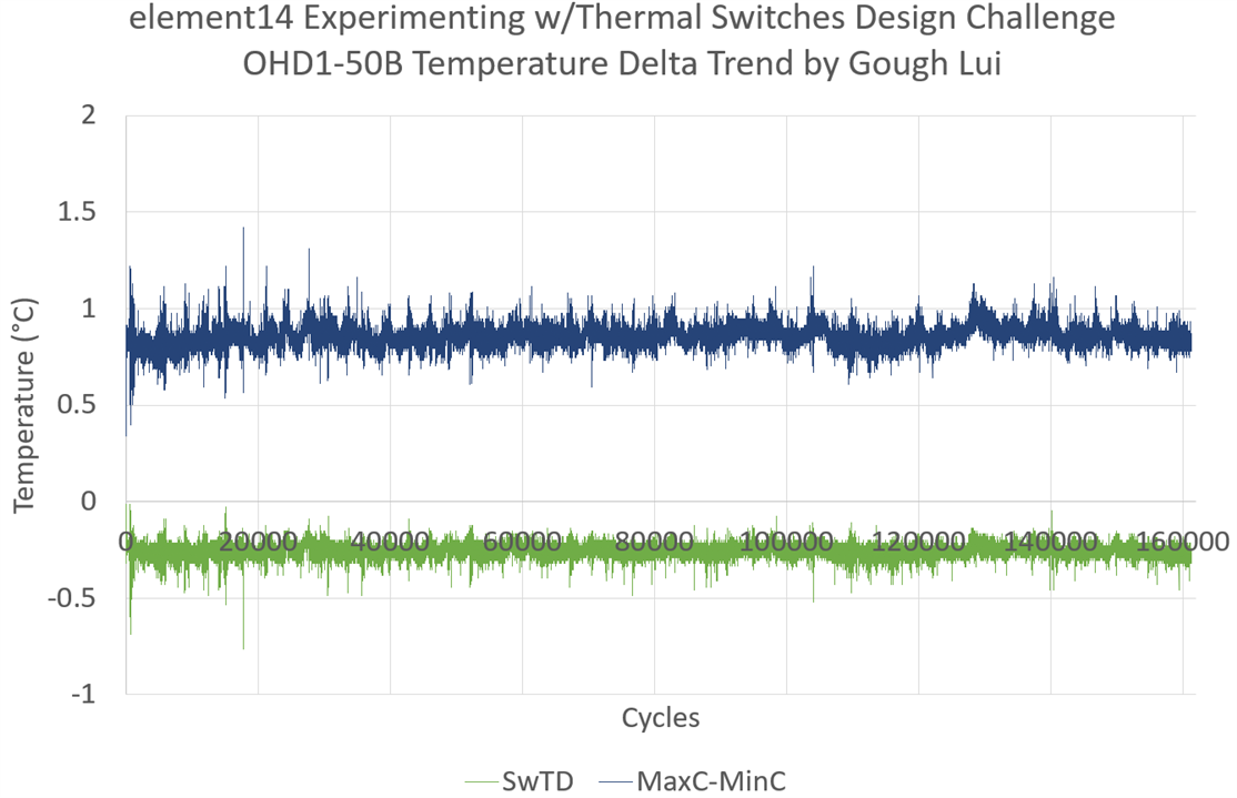
Taking the difference between the switching-on and switching-off temperatures, a negative temperature difference is found because of the effects of thermal lag. Instead, looking at the cycle range – that is, the difference between the maximum temperature and the minimum temperature throughout the cycle, shows very a stable characteristic with about 0.82°C with no discernible long-term trend.

Cycle times did show some diurnal variation but was still relatively stable throughout. This is mainly to verify that the experimental set-up did not significantly change over the course of the torture test.
M-TRS5-60B

The plot of raw temperature values for the 60°C switch similarly showed small variations (compared to the thermocouple and measurement system error) in the temperatures with a diurnal temperature variation.
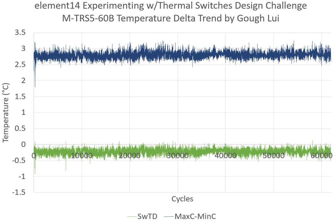
The hysteresis temperature difference value again was negative due to the effects of thermal lag. However, the cycle range temperature was a very stable 2.75°C with no obvious baseline wander, maintaining this value with a small amount of noise either side.

The cycle times did show some variation, but mostly controlled within a tight range except for when a window was initially open in my room and air was blowing directly on the test apparatus. This indicates that the test conditions were maintained throughout.
Summary
The plots definitively show the stability of the characteristics throughout the torture test. It is not unexpected to see virtually no measurable drift in characteristics, as the switching point is determined by the Curie point of the Thermorite® material which is a property that doesn’t “wear out” in the same way a bimetallic strip might. Instead, the lifetime of the underlying gas-filled reed capsule switch will likely control the lifetime of the switch and even under a full rated current resistive load, we have demonstrated cycle life exceeding 160,000 cycles.
The Final Results – Contact Resistance
By looking at the contact resistance, I was hoping to infer some information about the condition of the switch contacts. Contact resistance trends were derived from the measured on-state voltage by the B&K Precision DAS240-BAT Multi-Channel Recorder. This is not highly accurate due to the small voltages involved, but this measurement can be made cycle-by-cycle, in-situ, providing trends “as we go”. The accuracy of this measurement will not be as high as that of measuring the switches on an LCR meter, but should still give an idea of relative changes.
OHD1-50B

The OHD1-50B showed reducing average contact resistance initially which then pretty much stabilised. This may be because the contacts were wearing-in. The maximum contact resistance within the measurement window of each cycle did have some peaks which suggests that the contact may have bounced or crackled slightly after a switching event.
M-TRS5-60B

The M-TRS5-60B showed a relatively stable average contact resistance value over the measurement window, but had quite a few spiky events which seemingly reduced over time possibly as the contacts wore-in.

The tallest spike was a single sample of over 600mΩ which may have been because of contact bounce or crackle, but may also be because the apparatus may have been accidentally bumped. But the average value and minimum value are very similar, suggesting these maximum values are very transient.
Precision Measurement
To finalise the investigation on contact resistance, I decided to cut the switches out of the test assembly to connect the switches to my B&K Precision BA6010 Battery Analyzer to perform a precision measurement of post-experiment contact resistance under the same conditions as the initial check. This would provide the most accurate result, but would mean terminating the experiment permanently.
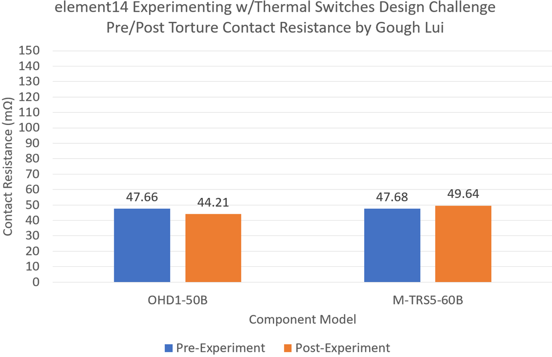
It seems that the contact resistance has only changed by a very small amount - if anything, it may have slightly reduced on the OHD1-50B and increased slightly with the M-TRS5-60B which may be due to the contacts wearing-in. I expect the switch still has quite a bit of life remaining and the claimed >500,000 cycle life may not be unreasonable as it is nowhere near the 150mΩ specification limit.
What Have I Learned?
For an “experimenting-with” style design challenge that only required two blogs, I’ve ended up doing a lot more than I had initially planned. However, throughout the process of unpacking, testing, torturing and designing with thermal switches, I feel that I have learned plenty of important facts about these deceptively simple components.
In the spirit of consolidating my learnings, I have compiled these thoughts as a series of key points:
- Kemet thermal switches are built around a gas-filled magnetic reed switch which is surrounded by various annular magnets, Thermorite® Curie-point engineered materials and spacers. Depending on the arrangement of components and the composition of Thermorite®, the switches are available in both make- and break-types of various temperature ratings (our kit included switches spanning 30°C-120°C). Because of the use of the material-properties of Thermorite®, the switching temperatures are stable over time and well-controlled.
- Measuring switching temperature is a complicated process due to the effects of thermal lag caused by thermal resistance and thermal mass. The location of the temperature probe, heat source and rate of heating/cooling all have effects on the measured results. Without an environmental chamber that circulates air continuously with controlled ramp rates, it is difficult to accurately determine the exact switching thresholds and hysteresis values, but the figures I obtained seem mostly to be in agreement with the datasheet claims.
- As the reed capsules are sealed, the switching lifetime of these thermal switches is claimed to be over 500,000 cycles. This experiment was able to demonstrate over 160,000 cycles, exceeding the rating of most competing technologies. This requires careful consideration of supporting components, especially electromechanical relays which may have a cycle life significantly shorter than this. The use of solid-state relays or MOSFETs to switch heavier loads using the switches appears to be prudent.
- The switches are available in a variety of packages with different ratings to suit different applications. This includes “plastic” packages with a square and round profile, optionally with mounting lugs for heatsink mounting and spade connections, aluminium mounting flanges or metal-bodied screw-in devices for automotive use. Depending on the package, weights for the supplied devices ranged from 1.05g to 15.25g.
- The thermal switch current ratings may seem limited, but informal testing seems to show they are capable of handling inrush currents up to 6x their rating upon which the contact resistance began to deviate (likely due to contact heating). The maximum voltage rating also seems reasonable, although exceeding this did provide some evidence of current leakage through the fill-gas and possible failure of the sealing of the reed capsule. For long-term reliability, it is important to respect all ratings – that includes the minimum current rating (to break through contact oxides), the maximum current rating (for contact heating), the maximum voltage rating (to avoid arcing that may damage the plating or occur in the fill-gas) and the maximum power rating (to avoid excess dissipation during switching).
- Cycle testing showed stable contact resistance behaviour over time, with one switch showing a slight reduction initially which may be attributed to better contact being made as the switches “wear-in”. In all cases, contact resistances measured below the manufacturer’s datasheet figures even after the torture test.
- As the thermal switches are based around magnetic reed switches, their state can be affected by external magnetic fields, thus the strength of the field and switch orientation should be taken into account. Strong magnets appear to be able to make the switch “stick” in some cases. They also appear to be affected by nearby ferromagnetic material (e.g. steel) which will cause deviations in switching temperature. As they do have magnets within them, they also do cause a small magnetic field to develop around the switches as well. The shape of these fields can provide information on the type of thermal switch.
- The thermal switches can also be affected by strong shocks which can cause the contacts to ring. The switches have a resonant frequency which could be excited by vibrations. My attempts to measure this seemed to imply different reed geometries producing different frequencies ranging from 1.4kHz to 30.8kHz depending on the model.
- As the thermal switches are electromechanical switches, they also exhibit contact bounce, however, it seems that this bounce is pronounced only in one of the switch directions (for the tested break type switch, it is upon switch closure) resulting in a bounce time lasting about 250µs.
- The switches are best suited for where reliable, binary outputs or direct control of low-power loads (relay coils, indicator lamps, small fans) are required. This includes applications such as over-/under-temperature detection where highly-reliable, simple, independent systems are required for safety reasons. They are also more suited for cycling applications than other thermal switch technologies, provided the cycle time or effective cycling rate is considered to ensure sufficient lifetime, as they do have a higher cycle lifetime compared to other technologies. However, if accurate knowledge of temperature and proportional control is desired, other forms of temperature sensing should be utilised, however the thermal switches may still be desirable to provide back-up protection against malfunctions for safety reasons.
Conclusion
Thermal switches may seem like simple components, but I hope that my experiences over the past eight weeks show that there is more than meets the eye. The Kemet thermal switches were able to prove their longevity in this full-load torture test which was terminated due to the design challenge ending, but in the process, I learned a lot about other aspects of their construction, operation and application. I hope these blogs have also helped you learn more about these components.
Thanks to element14 and Kemet for the opportunity to test these components and I look forward to seeing the results of all of the challengers!
[The Torturing Thermal Switches Blog Series Index]
- Blog #1: Torturing Thermal Switches – Cycle Testing Cut-in, Cut-out, Hysteresis & Contact Resistance
- Blog #2: Torturing Thermal Switches – Unboxing, Initial Characterisation & Experimental Refinements
- Blog #3: Torturing Thermal Switches – Magnetic Characteristics, Teardown, Overload Behaviour & Commencing the Cycle Experiment!
- Blog #4: Torturing Thermal Switches – Contact Bounce, Overvoltage & Building a Component/Filament Dryer
- Blog #5: Torturing Thermal Switches –Temperature Measurement Complexities, Switching Deviations, Data Analysis & Interim Results
- Blog #6: Torturing Thermal Switches – Latching Fault Circuit Design, Weighing In, and Checking Contact Resistance
- Blog #7: Torturing Thermal Switches – A Minor Glitch, *Final* Results & Conclusion (this post)
Top Comments