


Introduction
This is my third entry in The Eye on Intelligence design challenge. In the previous two, I introduced the Digilent Arty Z7 development board and the PYNQ development framework. PYNQ enables the creation of designs in adaptive computing environments using Python, combining the power of microcontrollers with modifiable circuitry or programmable logic implemented on an FPGA.
In the last blog, I demonstrated how certain fruits could be identified using Haar Cascade classifiers and conducted experiments detecting bananas. In this third blog, I address a crucial aspect of my smart fruit scale project: weighing the fruits.
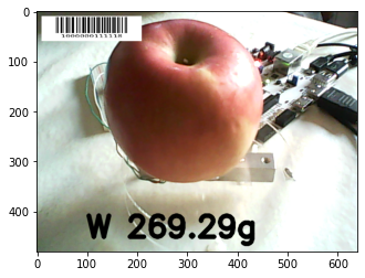
The smart scale will identify the fruit to be weighed and perform the weighing. As output, it will display on the screen the image captured for classification, the weight, and a barcode indicating the classification and weight.

In the image, you can see the barcode EAN13 1000000002546, which corresponds to an apple classification and a weight of 254 grams. The 6 is the control digit of the EAN13. Weighing is performed with a load cell and the Zynq's analog-to-digital converter. To accommodate the small signal produced by the cell, the system uses an instrumental amplifier.
In this blog, I make a brief introduction to load cells for weighing and discuss the results I obtained in my experiments with them. Then, I introduce instrumental amplifiers and report my experiments with an Analog Devices instrumental amplifier. I explore capturing the signal with the Zynq's analog-to-digital converter from PYNQ. Finally, I integrate everything by creating various overlays on the captured image to show the weighing and the barcode, allowing integration with current supermarket cash registers.
Introduction to Strain Gauge Load Cells
A strain gauge load cell is a sensor that uses the deformation of one or more strain gauges bonded to its body to measure force. Bar strain gauge load cells, for example, often have a "Z" shape. This design allows the force (often torque) to be applied to the bar, causing it to bend. The four strain gauges strategically placed on the cell measure this bending distortion. Two gauges typically measure compression, while the other two measure tension. By connecting these four strain gauges in a Wheatstone bridge formation, we can accurately measure the small changes in resistance they experience, which translates to the applied force.
resource: https://www.omega.com/en-us/resources/wheatstone-bridge
The image shows two load cells. One was salvaged from an old kitchen scale, and the other, the one with holes, was acquired for this design challenge. Both are suitable for up to 5 kg.

The holes are used to mount the cell in the typical Z-shaped configuration: base-cell-top. They are of two different sizes, which is the most common configuration for this type of cell. Other scales have four separate cells that are placed in a square at the ends of the base.

I bought a very inexpensive kit that comes with a small acrylic base and top, along with a couple of spacers to mount the cell between the two. In the picture, the sensor is mounted and ready for experiments.
To check the cell’s operation, I used a Multicomp MP730026 digital multimeter. Connected to two 1.5 V batteries in series, the cell’s strain gauge bridge is excited with 3 V. Note the small variation that occurs when placing an apple on the sensor, with variations of tenths of a millivolt. The multimeter shows 0.55 mV with the sensor unloaded. Even the lid of the scale unbalances the bridge, and it shows 0.69 mV when placing the apple in the center of the top, a difference of just 0.14 mV.
These values are too low to be measured with the Zynq’s analog-to-digital converter, so I need to adjust them by amplifying the signal. I studied possible alternatives, starting with a precision 24-bit analog-to-digital converter (ADC) designed for weigh scales and industrial control applications, such as the HX711.
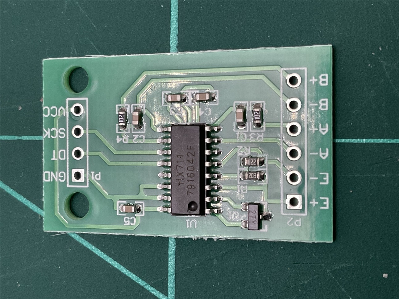
https://cdn.sparkfun.com/assets/b/f/5/a/e/hx711F_EN.pdf
However, I decided to give the Zynq’s analog-to-digital converter a try to give it more prominence by using an instrumental amplifier to amplify the signal.
Instrumentation Amplifiers
An instrumentation amplifier (InAmp) is a specialized type of differential amplifier designed for precise amplification of low-level signals, particularly in measurement and instrumentation applications. It's characterized by:
- High common-mode rejection ratio (CMRR): This ability to suppress common-mode signals, like noise or interference, is crucial for accurate measurements.
- High input impedance: This prevents the amplifier from loading the signal source, ensuring that the original signal remains undistorted.
- Adjustable gain: The gain of an instrumentation amplifier can be easily adjusted using a single external resistor, making it flexible for various applications.
- Low offset voltage and drift: These characteristics contribute to high accuracy and stability.
- Low noise: Instrumentation amplifiers are designed to minimize noise, which is essential for amplifying weak signals.
While reviewing the materials I had at home to see if I had any samples of an instrumental amplifier suitable for this application, I found a sample of the Analog Devices AD8226. After examining its characteristics, it seemed like a good candidate.
Analog Devices AD8226
The AD8226 is a wide supply range, rail-to-rail output Instrumentation Amplifier. (https://www.analog.com/media/en/technical-documentation/data-sheets/ad8226.pdf)
Its key features and benefits:
- Wide Supply Range and Input Voltage: Operates on supplies from ±1.35 V to ±18 V (dual) or 2.2 V to 36 V (single). Handles input voltages beyond supply rails, up to ±35 V.
- Flexible Gain Setting: A single external resistor sets gain between 1 and 1000.
- Rail-to-Rail Output: Maximizes signal utilization.
- Low Bias Current: Facilitates open wire detection.
- Robust Design: Suitable for real-world sensor applications.


The AD8226 has a differential input, allowing it to directly measure the voltage difference between the bridge terminals. The high CMMR and low offset are good for accurately detecting the small voltage changes caused by the strain gauge.
Gain Selection
Placing a resistor across the Rg terminals sets the gain of the AD8226, which can be calculated using the following gain equation:
Rg = 49.4 kOhm / (G-1)

Using the AD8226 for Amplifying a Strain Gauge Bridge Output Signal:
This is the schematic I used for testing.

Overall Circuit Function:
- The strain gauge bridge produces a voltage difference proportional to the applied strain.
- The AD8226 amplifies this voltage difference, providing a scaled output signal.
- The 10µF and 0.1µF capacitors are used to decouple the power supply and reduce noise
To determine if I could safely use the AD8226 with the Arty Z7’s analog inputs, I began by testing it with a 1.7 kΩ resistor to achieve an approximate gain of 30x
I used the following tool provided by Analog Devices to determine the operating range of the AD8226:


The Diamond Plot graph focuses on two main elements: the Operating Range and Device Limits.
- Operating Range: Represented as a red box around voltages where the circuit should operate, based on the input signal and gain of the in-amp. It plots the common mode voltage (Vcm) against the output voltage (Vout).
- Device Limits: Illustrated by various shapes indicating the device’s operating limits. The white area shows the valid region where the device works properly, while the grey area indicates invalid regions."
Using a Multicomp MP720015 digital multimeter and two 1.5V batteries to obtain 3V, I made some checks with one of the weighing objectives in the smart scale project, an apple
In the absence of a load, the multimeter shows 1.589 volts, and when placing the apple on the scale, the multimeter shows 1.593 volts, indicating a 4 mV difference. By calculating the gain and comparing it with the 0.14 mV obtained in the previous experiment without the difference amplifier, I get a gain of
(4/0.14) = 28.5.
This is quite close to the AD8226 datasheet’s indicated gain of
(49.4 / 1.75) + 1 = 29.2
Considering that I am not using precision resistors, it seems that the circuit works adequately for my interests in this project.
Using the Zynq XADC to read voltage changes
The XADC core within the Zynq is a dual-channel 12-bit analog-to-digital converter capable of operating at 1 MSPS. Either channel can be driven by any of the analog inputs connected to the shield pins. The XADC core is controlled and accessed from a user design via the Dynamic Reconfiguration Port (DRP). The DRP also provides access to voltage monitors that are present on each of the FPGA’s power rails, and a temperature sensor that is internal to the FPGA.
For this experiment we will use the following PINs on the Arty Z7 board:
Pin Name |
Shield Function | Arty Z7 Connection |
|---|---|---|
|
A0-A5 |
Single-Ended Analog Input |
See Section titled “Shield Analog I/O” |
|
XGND |
XADC Analog Ground |
Connected to net used to drive the XADC ground reference on the Zynq (VREFN) |
|
XVREF |
XADC Analog Voltage Reference |
Connected to 1.25 V, 25mA rail used to drive the XADC voltage reference on the Zynq (VREFP) |
|
3V3 |
3.3V Power Rail |
Connected to the Arty Z7 3.3V Power Rail (See the “Power Supplies” section) |
|
GND, G |
Ground |
Connected to the Ground plane of Arty Z7 |
 The pins labeled A0-A11 and V_P/V_N are used as analog inputs to the XADC module of the Zynq. The Zynq expects that the inputs range from 0-1 V. On the pins labeled A0-A5 the board has an external circuit to scale down the input voltage from 3.3V.

This circuit allows the XADC module to accurately measure any voltage between 0V and 3.3V (relative to the Arty Z7's GND) that is applied to any of these pins. They also can be used as Digital inputs or outputs, as they are also connected directly to the Zynq PL before the resistor divider circuit.
The image shows the load cell mounted on the Z-frame of the scale, with the output signal of the load cell amplified by the AD8226 instrumental amplifier. The amplified output is connected to the analog input A0 of the Arty Z7 development board. The AD8226 reference is supplied by the XVREF port of the Arty Z7.

Reading the analog values from a PYNQ from a Notebook
We can read the analog value converted by the analog-to-digital converter in several ways: using the Zynq's Programmable Logic, through a program running on one of the Zynq's ARM Cortex A9 physical microcontrollers or running on a Microblaze soft processor. The versatility of a SoC like the Zynq allows us to perform this task in the best way we consider. In this case, we are going to perform the reading in the simplest way using PYNQ with a Jupyter notebook running on Linux.
The image shows a session with a Jupyter notebook reading the value converted by the Zynq's XADC.

|
|
 |

Scale Calibration
After checking the first results and seeing that the gain of 30 was a bit short of my expectations, I experimented until I obtained the maximum gain that did not produce strange results. With the help of the Analog Devices tool and several tests, I finally decided to use a 270 Ω resistor, which left the system with a gain of 184, about 6 times more than the previous one

All that was left was to check the linearity of the measurements and calibrate the system to obtain the grams from the changes detected in the voltage. To do this, I used a commercial kitchen scale, one of those that have 4 load cells at the ends, to check the weight of different objects and compare them with the voltage increases obtained. With the help of an Excel spreadsheet and observing the linearity in the range of weights to be measured, I obtained the equation of a regression line that will allow the Jupyter notebook to convert the voltage value read into the weight in grams of the object to be weighed.

Linear regression: f(x) = 8602.83843341191x - 11827.7176859981
If you are interested in this topic, I found the following document from Texas Instruments: A Basic Guide to Bridge Measurements (Rev. A) (ti.com)
This document provides an overview of bridge circuits, how they are used to measure different forces, and how to achieve accurate measurements with precision analog-to-digital converters
Scale User Interface
Displaying Real-Time Information on the HDMI Screen
At this point, we already have several very important parts of the smart scale. We have been able to obtain real-time images of the fruit, recognize some fruits using the cascade classifiers, and we can obtain the weight of the fruit to be classified. In this section, we will see how to display this information on the screen and how to generate a barcode that can give us this information to communicate it to another system, such as a supermarket cash register.
To display real-time information on the HDMI screen, we will use the following steps:
- Set Up the HDMI Output: Configure the HDMI output on the Arty Z7 to display the user interface.
- Design the User Interface: Create a user-friendly interface that shows the real-time weight, fruit type, and other relevant information.
- Integrate the Barcode Generator: Implement a barcode generator that encodes the fruit’s weight and type. This barcode can be scanned by a supermarket cash register to retrieve the information.
The smart scale must provide a seamless and efficient user experience, making it easy to classify and weigh fruits while also integrating with other systems for further processing.
Installing a barcode library
I tried several libraries for barcode generation, and fortunately, there are many to choose from when working with Python. In the end, I decided on the python-barcode library because it is implemented entirely in Python, making it easy to integrate into almost any architecture that supports the same version of Python. You can find it on GitHub at WhyNotHugo/python-barcode
Installation
To install the library, use the following command:
pip install python-barcode
Version installed: 0.15.1
The library is installed in the following path:
/usr/local/share/pynq-venv/lib/python3.10/site-packages
For more information, refer to the python-barcode 0.15.1 documentation. python-barcode 0.15.1 documentation
Creating an EAN13 Format for the Smart Scale
In order to integrate the smart scale with current cash register systems, the project uses two schemes: the generation of a standard EAN13 barcode and/or serial communication with the cash register similar to that produced by a barcode reader. This communication contains the information of the classified fruit/vegetable and the weight of the item.
For example, in the image we would have:
100000: Apples
000254: 254 grams

The image of the barcode and the weight obtained by the scale are displayed superimposed on the image captured by the webcam on an HDMI screen, allowing the cashier to capture the barcode with a CCD barcode reader.
Calibrating the Scale
To calibrate the scale, the system must take measurements with nothing on top to adjust the weighing. It is advisable to perform this adjustment often. The image shows the deviation. Many of the scales I have seen in supermarkets for this type of weighing have a tolerance of ±5g, and they usually round up.

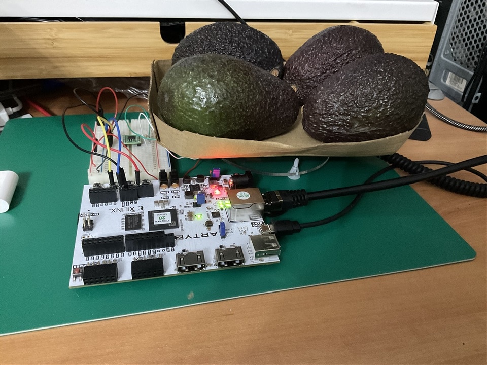
The Setup for the Experiments
In the picture, I show you the setup for my experiments. The Digilent Arty Z7 development board is connected to my local network with an Ethernet cable. It has a webcam connected through the USB port, and the HDMI output is connected to a small HDMI display. The weight sensor, the load cell, is connected to an instrumental amplifier that connects to the A0 port of the XADC analog-to-digital converter of the Zynq on the Arty Z7, which supports up to 3.3V. The Arty board provides the 3.3V that powers the instrumental amplifier and the 1.25V reference for the analog-to-digital converter. The laptop connects to a Notebook server that runs on one ARM processor of the Zynq on the Arty Z7.

Jupyter Notebook
Summary and conclusions
In this third entry for “The Eye on Intelligence” design challenge, I introduced strain gauge load cells, explaining their design and function in measuring force. Experiments with load cells highlight the small voltage variations produced when weighing fruits, necessitating the use of instrumental amplifiers to amplify these signals.
The experiments demonstrated that strain gauge load cells are effective for measuring small forces, but their output signals are very low. Instrumental amplifiers are essential to amplify these small signals to a measurable range for the Zynq’s XADC. Successfully integrating the load cell, amplifier, and XADC with the PYNQ framework allows for accurate fruit weighing and classification. This integration shows promise for creating a functional smart scale that can be used in supermarkets, showcasing the practical application of adaptive computing and embedded systems.
FruitVision Scale Blogs Series
- Blog 1 - FruitVision Scale - Digilent Arty Z7 - AMD Zynq-7000 - Overview
- Blog 2 - FruitVision Scale - PYNQ on the Digilent Arty Z7 - Quickstart
- Blog 3 - FruitVision Scale - Weighing strategies with load cells using the Digilent Arty Z7
- Blog 4 - FruitVision Scale - FPGA-Based HX711 Driver for Precision Weighing with AMD PYNQ
- Blog 5 - FruitVision Scale - Exploring Deep Learning Applications with AMD Zynq 7000
- Final - FruitVision Scale
-

rsc
-
Cancel
-
Vote Up
0
Vote Down
-
-
Sign in to reply
-
More
-
Cancel
-

michaelkellett
in reply to rsc
-
Cancel
-
Vote Up
0
Vote Down
-
-
Sign in to reply
-
More
-
Cancel
-

javagoza
in reply to michaelkellett
-
Cancel
-
Vote Up
0
Vote Down
-
-
Sign in to reply
-
More
-
Cancel
-

javagoza
in reply to javagoza
-
Cancel
-
Vote Up
0
Vote Down
-
-
Sign in to reply
-
More
-
Cancel
-

javagoza
in reply to javagoza
-
Cancel
-
Vote Up
0
Vote Down
-
-
Sign in to reply
-
More
-
Cancel
Comment-

javagoza
in reply to javagoza
-
Cancel
-
Vote Up
0
Vote Down
-
-
Sign in to reply
-
More
-
Cancel
Children