


Recap
I'm building a smart solar monitoring system that uses three panels with a clean reference to eliminate weather effects and directly measure dust-induced losses in real time. One panel stays pristine as a baseline, and comparing the two under identical sky conditions gives a performance ratio that reveals soiling immediately. The goal is to use environmental sensors and edge AI to predict exactly when cleaning is needed, before efficiency drops enough to impact revenue. This beats fixed-schedule cleaning or waiting for output to degrade.Also this is complementary to my Master's thesis of a minute Shape memory Alloy based solar panel cleaning robot
Previous posts:
- SolarSense - Part 1 - Introduction, The POC Built and The Plan
- SolarSense - Part 2 - Can Arduino CAN?
- SolarSense - Part 3 - PCB Schematics Walkthrough
- SolarSense - Part 4 - CAN Protocol Deep Dive and Implementation
- SolarSense - Part 5 - Making an Live Dashboard using Lab View
Why a Junction Thermocouple?
If you read Part 1, you would have seen that in the Proof of Concept I was already using the SEN66 for ambient temperature. And going forward I am planning to use the Omega HX94C sensor for temperature and relative humidity — it is a more accurate sensor for ambient conditions and handles the Kerala humidity far better.
So then, why do I also have a thermocouple on each panel? Because a thermocouple measures surface temperature, not ambient. What I want to know is how hot the panel itself gets, not the air around it. The two are very different. A panel sitting under direct sun in Kerala can be 20–30°C hotter than the air temperature. That heat is not just a background condition, it directly affects the panel's output. Crystalline silicon panels lose roughly 0.4% of their output per degree Celsius of cell temperature rise. Over a full day of sun exposure that is a measurable and significant drop.
The key insight: I am not just monitoring soiling. I am studying what long-term heat exposure does to each panel's efficiency over time. If one panel consistently runs hotter than the others. maybe due to its mounting position, or partial shade that creates hotspot effects that shows up in the data as a slow efficiency drift that has nothing to do with dust. Without the surface temperature measurement I would not be able to separate that from actual soiling. Now, these are just my hypothesis, and hope to get it proven. What better way to make use of the OmegaDwyer 5SRTC-TT-K-24-72 Thermocouple, K, 0 °C, 260 °C, 80 ", 2 m (Pack of 5)
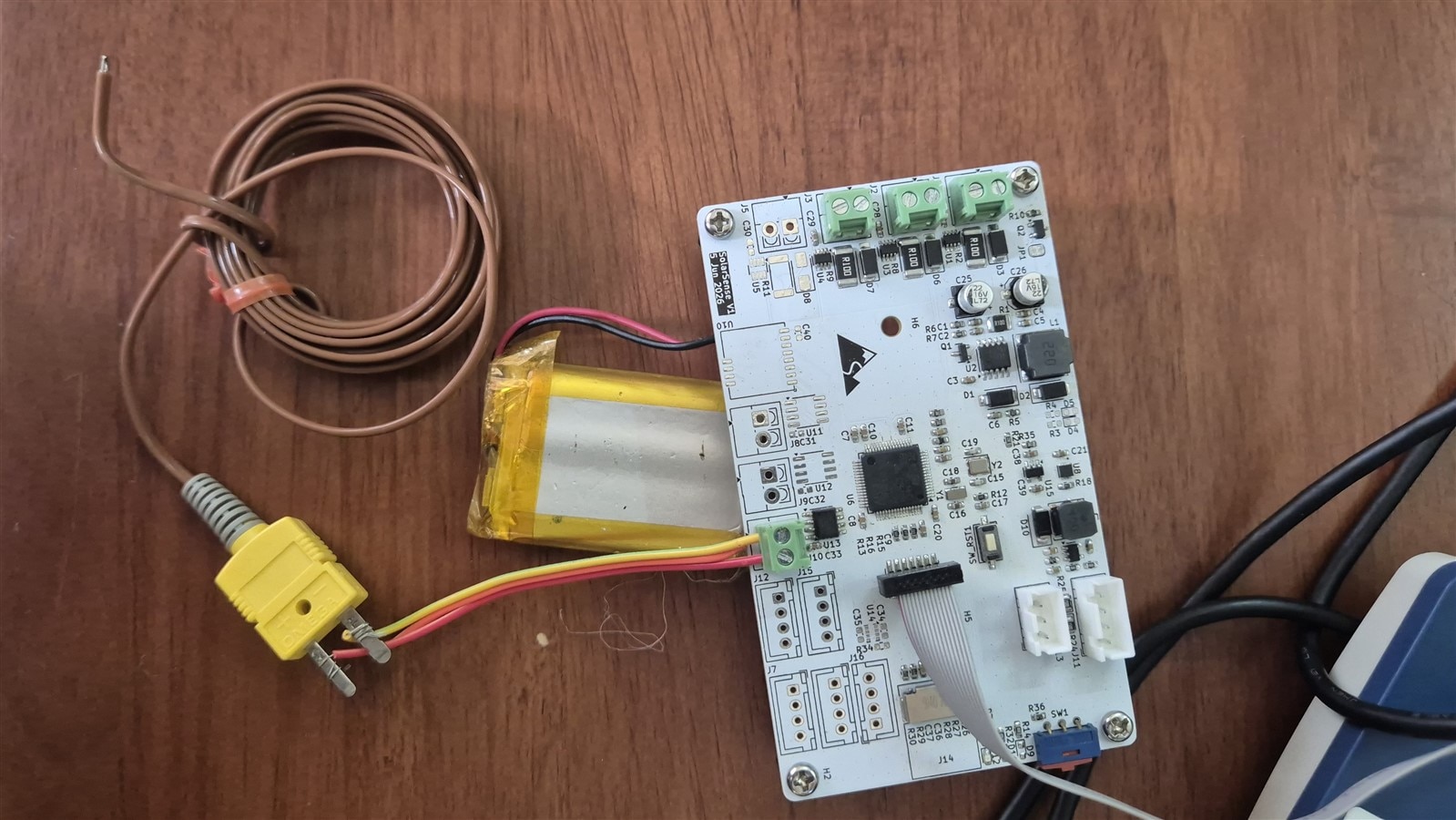
The PCB has three MAX31855KASA+ thermocouple amplifier chips, one per panel with K-type thermocouple inputs. For now, I am going to solder only one chip. I actually found that the module is cheaper than the chip itself, so I just harvested it from the module.
Interfacing with MAX31855
The MAX31855 is a single-chip thermocouple amplifier with SPI output. You wire a K-type thermocouple to the two input pins, and the chip handles the cold-junction compensation internally using a temperature sensor on the die itself. What comes out of the SPI port is a fully compensated temperature reading. No lookup tables, no Seebeck coefficient math in firmware. The chip does it all.
The catch? It is completely read-only. There are no configuration registers. No setup. No init sequence. You pull CS low, clock out 32 bits, release CS, and you have your reading. That is the entire protocol.
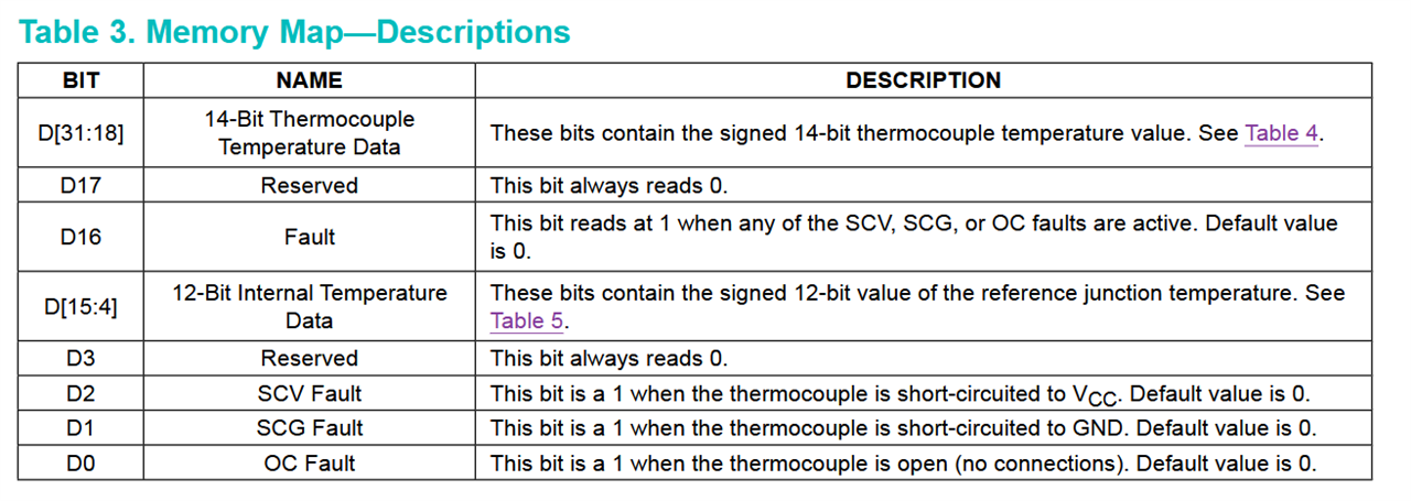
Those 32 bits break down like this:
The three fault bits in [2:0] tell you exactly what is wrong with the thermocouple wiring. OC means nothing is plugged in. SCG and SCV mean the wire is touching something it should not. When any of these are set, bit 16 goes high and the thermocouple reading in [31:18] is cleared to zero. Here is the Descriptions from the Datasheet
Touching a Dusty Part of CubeMX and Extracting Data from SPI Frame
Usually, in CubeMX I rarely configure settings of SPI, I just make it the default settings of 8Bits per SPI frame.But 32Bits is frame size? My LORA Module required 16bits frame. So either make it 32bus for now, then manage it when i actually start using lora or I can make it future proof now. So, Math Says 32 bits is just two 16-bit transfers. HAL can do two back to back with CS held low. No reconfiguration needed, no disruption to the lora driver. and I had to keep the SPI Clock speed at 5Mhz as limited by the MAX31855. To set these, I went to a part of CubeMX where I have rarely been.

This settings translate to
hspi1.Instance               = SPI1;
hspi1.Init.Mode              = SPI_MODE_MASTER;
hspi1.Init.Direction         = SPI_DIRECTION_2LINES;
hspi1.Init.DataSize          = SPI_DATASIZE_16BIT;
hspi1.Init.CLKPolarity       = SPI_POLARITY_LOW;   /* CPOL = 0 */
hspi1.Init.CLKPhase          = SPI_PHASE_1EDGE;    /* CPHA = 0 */
hspi1.Init.NSS               = SPI_NSS_SOFT;
hspi1.Init.BaudRatePrescaler = SPI_BAUDRATEPRESCALER_16; /* 80MHz/16 = 5MHz */
hspi1.Init.FirstBit          = SPI_FIRSTBIT_MSB;
HAL_SPI_Init(&hspi1);
The actual read in the driver then looks like this:
static HAL_StatusTypeDef read_raw(MAX31855_t *dev, uint32_t *raw)
{
  uint16_t w[2];
  HAL_GPIO_WritePin(dev->cs_port, dev->cs_pin, GPIO_PIN_RESET);
  HAL_StatusTypeDef st = HAL_SPI_Receive(dev->hspi, (uint8_t *)w, 2, SPI_TIMEOUT_MS);
  HAL_GPIO_WritePin(dev->cs_port, dev->cs_pin, GPIO_PIN_SET);
  if (st == HAL_OK)
    *raw = ((uint32_t)w[0] << 16) | w[1];
  return st;
}
For the Thermocouple temperature i used the code to extract the data from the SPI Frame
int32_t t = (int32_t)(int16_t)(raw >> 16) >> 2;
and for the Cold junction
int32_t c = (int32_t)(int16_t)(raw & 0xFFFF) >> 4;
The Full Driver
here is the driver's
/**
 * @file    max31855.h
 * @brief   Driver for the Maxim MAX31855 SPI thermocouple amplifier.
 *
 * SolarSense populates three MAX31855KASA+ (K-type) on SPI1:
 *
 * The device is read-only; no configuration registers exist. One 32-bit
 * SPI frame (two 16-bit HAL transactions) yields the thermocouple temp
 * (0.25 °C/LSB) and the on-chip cold-junction temp (0.0625 °C/LSB), plus
 * three open/short fault bits.
 */
#ifndef MAX31855_H
#define MAX31855_H

#include "stm32l4xx_hal.h"

/* Fault bits returned in the faults byte (mirrors hardware bits [2:0]). */
#define MAX31855_FAULT_OC   0x01U  /* thermocouple open circuit   */
#define MAX31855_FAULT_SCG  0x02U  /* thermocouple shorted to GND */
#define MAX31855_FAULT_SCV  0x04U  /* thermocouple shorted to VCC */

typedef struct {
    SPI_HandleTypeDef *hspi;
    GPIO_TypeDef      *cs_port;
    uint16_t           cs_pin;
    uint8_t            present;   /* 1 after a successful Init() SPI probe */
} MAX31855_t;

/* Bind the driver to an SPI bus and a software CS pin. Performs one SPI
   read to confirm the device is wired. Sets present = 1 on success. */
HAL_StatusTypeDef MAX31855_Init(MAX31855_t *dev, SPI_HandleTypeDef *hspi,
                                GPIO_TypeDef *cs_port, uint16_t cs_pin);

/* Read thermocouple and cold-junction temperatures (tenths of °C, signed)
   and the fault byte. Any output pointer may be NULL.
   Returns HAL_OK on a clean read; HAL_ERROR if the SPI transaction fails.
   A non-zero *faults value means the thermocouple has a wiring fault and
   *tc10 is unreliable, but *cj10 (board ambient) remains valid. */
HAL_StatusTypeDef MAX31855_Read(MAX31855_t *dev,
                                int32_t *tc10, int32_t *cj10,
                                uint8_t *faults);

#endif /* MAX31855_H */```/**
* @file max31855.c
* @brief Driver for the Maxim MAX31855 SPI thermocouple amplifier.
*/
#include "max31855.h"
#define SPI_TIMEOUT_MS 10U
/* Pull CS low, clock out 32 bits as two 16-bit HAL frames, release CS. */
static HAL_StatusTypeDef read_raw(MAX31855_t *dev, uint32_t *raw)
{
uint16_t w[2];
HAL_GPIO_WritePin(dev->cs_port, dev->cs_pin, GPIO_PIN_RESET);
HAL_StatusTypeDef st = HAL_SPI_Receive(dev->hspi, (uint8_t *)w, 2, SPI_TIMEOUT_MS);
HAL_GPIO_WritePin(dev->cs_port, dev->cs_pin, GPIO_PIN_SET);
if (st == HAL_OK)
{
/* SPI1 is MSB-first 16-bit mode, so w[0] = bits[31:16], w[1] = bits[15:0]. */
*raw = ((uint32_t)w[0] << 16) | w[1];
}
return st;
}
HAL_StatusTypeDef MAX31855_Init(MAX31855_t *dev, SPI_HandleTypeDef *hspi,
GPIO_TypeDef *cs_port, uint16_t cs_pin)
{
dev->hspi = hspi;
dev->cs_port = cs_port;
dev->cs_pin = cs_pin;
dev->present = 0;
/* No config registers to write; probe by doing one SPI read. */
uint32_t raw;
if (read_raw(dev, &raw) != HAL_OK)
return HAL_ERROR;
dev->present = 1;
return HAL_OK;
}
HAL_StatusTypeDef MAX31855_Read(MAX31855_t *dev,
int32_t *tc10, int32_t *cj10,
uint8_t *faults)
{
uint32_t raw;
HAL_StatusTypeDef st = read_raw(dev, &raw);
if (st != HAL_OK)
return st;
if (faults)
*faults = (uint8_t)(raw & 0x07U);
/* Thermocouple temp: bits[31:18], 14-bit two's complement, 0.25 °C/LSB.
Cast top half to int16_t (sign bit preserved), arithmetic-right-shift
by 2 to drop the reserved bit and FAULT bit.
Tenths: raw14 × 0.25 × 10 = raw14 × 5 / 2. */
if (tc10)
{
int32_t t = (int32_t)(int16_t)(raw >> 16) >> 2;
*tc10 = (t * 5) / 2;
}
/* Cold-junction temp: bits[15:4], 12-bit two's complement, 0.0625 °C/LSB.
Same trick on the bottom half; shift right 4 drops reserved + fault bits.
Tenths: raw12 × 0.0625 × 10 = raw12 × 10 / 16. */
if (cj10)
{
int32_t c = (int32_t)(int16_t)(raw & 0xFFFFU) >> 4;
*cj10 = (c * 10) / 16;
}
return HAL_OK;
}this plus a lot of Serial print commands, Get the output

Now, the serial port is going to output a lots of data because I just put in the template for all sensors so that i can test it out with the LabView. But the tc3_c and tc3_cj are the numbers that matter. But it was not right, It showed 305 and 308 which means it is 3.05 and 3.08deg respectively (look at the top few lines of the serial). I simply multiplied the value in the code by 10 to get 3070 and 3080 respectively.There was nothing logical i know or found to make this multiplication, but it simply made sense to do it. I tried holding the junction with my hand and the temperature rose accordingly.
How Accurate am I reading it?
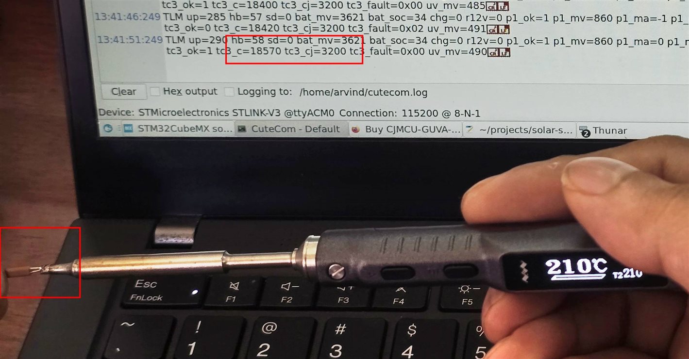
This is going to be a difficult one to answer because I do not have a True Reference or A Calibrated device to measure and check. But for now, I tired reading at the tip of my TS101 soldering station set at 210 deg C, I got 185 degC. Now, the Tip might not be exactly 210deg depending on where the control sensor of the soldering iron is, but I am gonna see if calibrating it it by a combination of Boiling water and Ice will be helpful. That i will document in the last post.
Final Notes
This being a stretch goal, I completed it before even completing my primary goals just because it was easy and convenient. But at this time of writing the post I have completed all of them and I am collecting data from the final device. More posts to come.