


Introduction
In the current exercise, I want to evaluate the portability and reusability features provided by the Vitis Unified Software Platform environment to migrate an application I developed with a Spartan-7 FPGA, implementing a MicroBlaze soft processor, to the MiniZed architecture, a single-core Zynq.
A few months ago, I explored the possibilities of AMD Vitis and Vivado tools for rapid prototyping. To explore those possibilities, I built a simple environmental monitor that reported ambient temperature and relative humidity on a small OLED display. For that development, I used a MicroBlaze soft processor created within AMD's Spartan-7 FPGA from the 7 series of FPGAs.
Let's see how complicated it is to migrate the solution based on the Microblaze soft processor to the Minized with a Zynq SoC.
Table of Contents
- Introduction
- Comparing Microblaze to Zynq based solutions
- Spartan-7 FPGA Microblaze Original Design
- Migrating the system between two differents Spartan-7 development boards
- Migrating from the MicroBlaze/Spartan-7 to the Zynq/Artix-7
- The Pmod Sensor and Actuator Modules
- Designing the new hardware with the Zynq
- IP Catalog
- Configuring the Zynq Processing System
- Finding package PINs from the schematics
- Programming the software from AMD Vitis
- Plug and Program the Device
- Summary
- References
- Path to Programmable III Training Blog Series
Comparing Microblaze to Zynq based solutions
First a little comparison between the two architectures.
The MicroBlaze CPU is a family of drop-in, modifiable preset 32-bit/64-bit RISC microprocessor configurations designed by AMD for their FPGAs. It offers flexibility and can be tailored to meet specific application requirements. Programmed with high-level languages such as C/C++, it provides a cost-effective solution for software-centric designs. It is fully implemented within the FPGA fabric, making it a compact and efficient option.
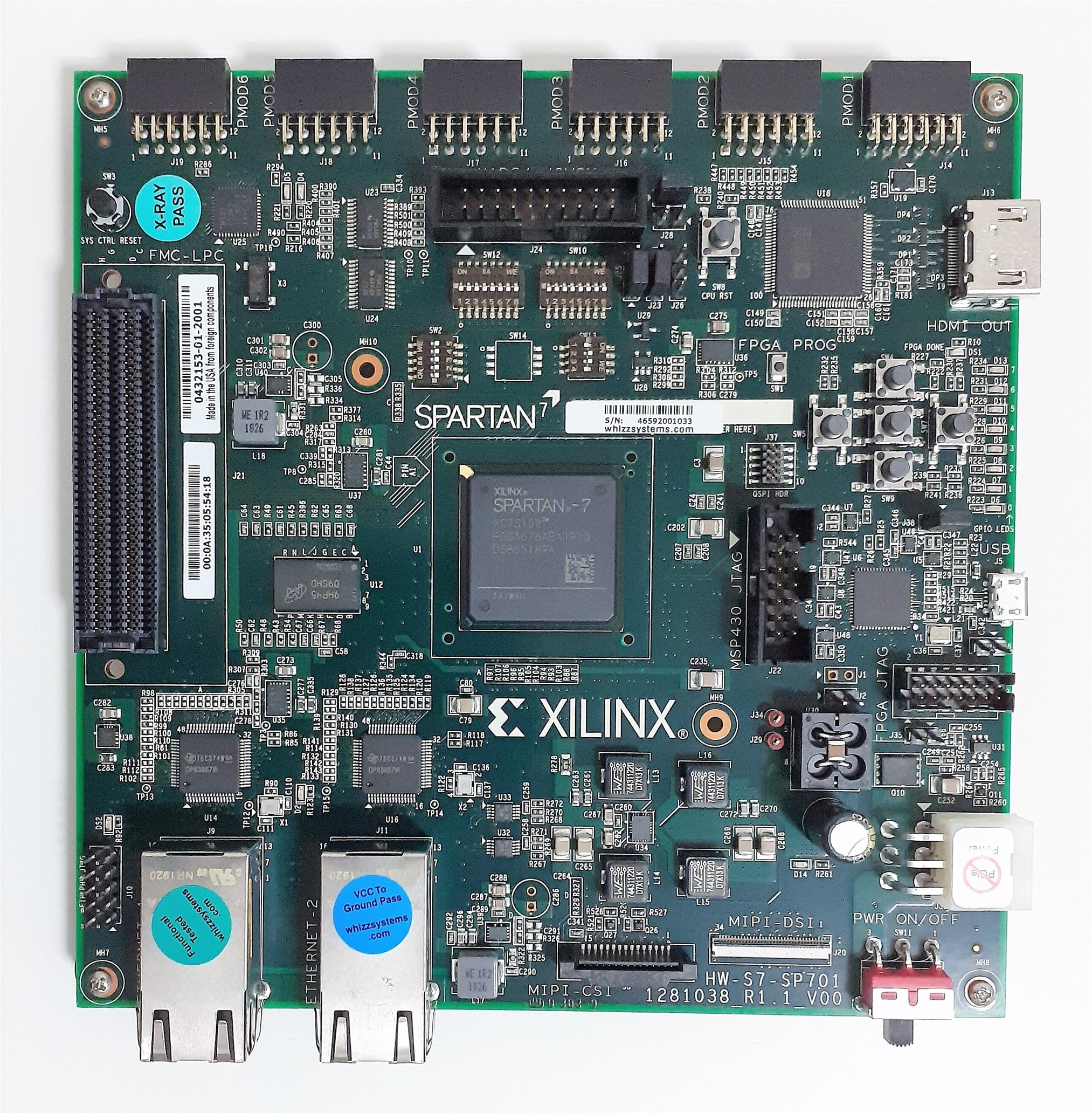
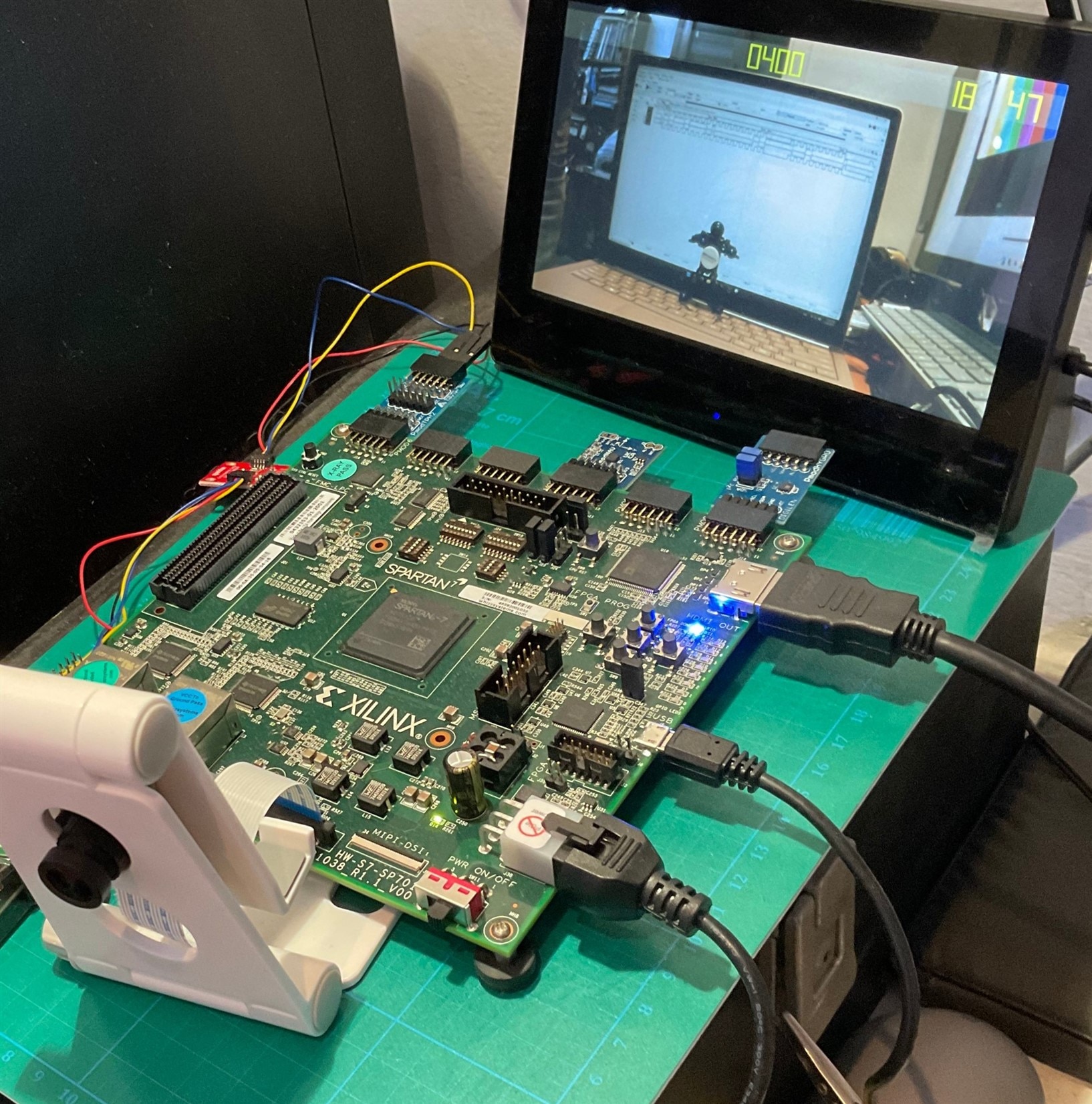
The AMD SP701 development board, as depicted in the picture, serves as an excellent example of a development board suitable for designing projects based on the MicroBlaze soft processor. The board provides a robust and versatile platform for implementing FPGA designs utilizing the MicroBlaze processor. The Spartan-7 does not integrate an Arm processor subsystem. The board implements an on-board system controller MSP430 not included in the Spartan-7 chip.
The Spartan 7 FPGAs are designed for I/O optimization with the highest performance-per-watt.
AMD SP701 development board
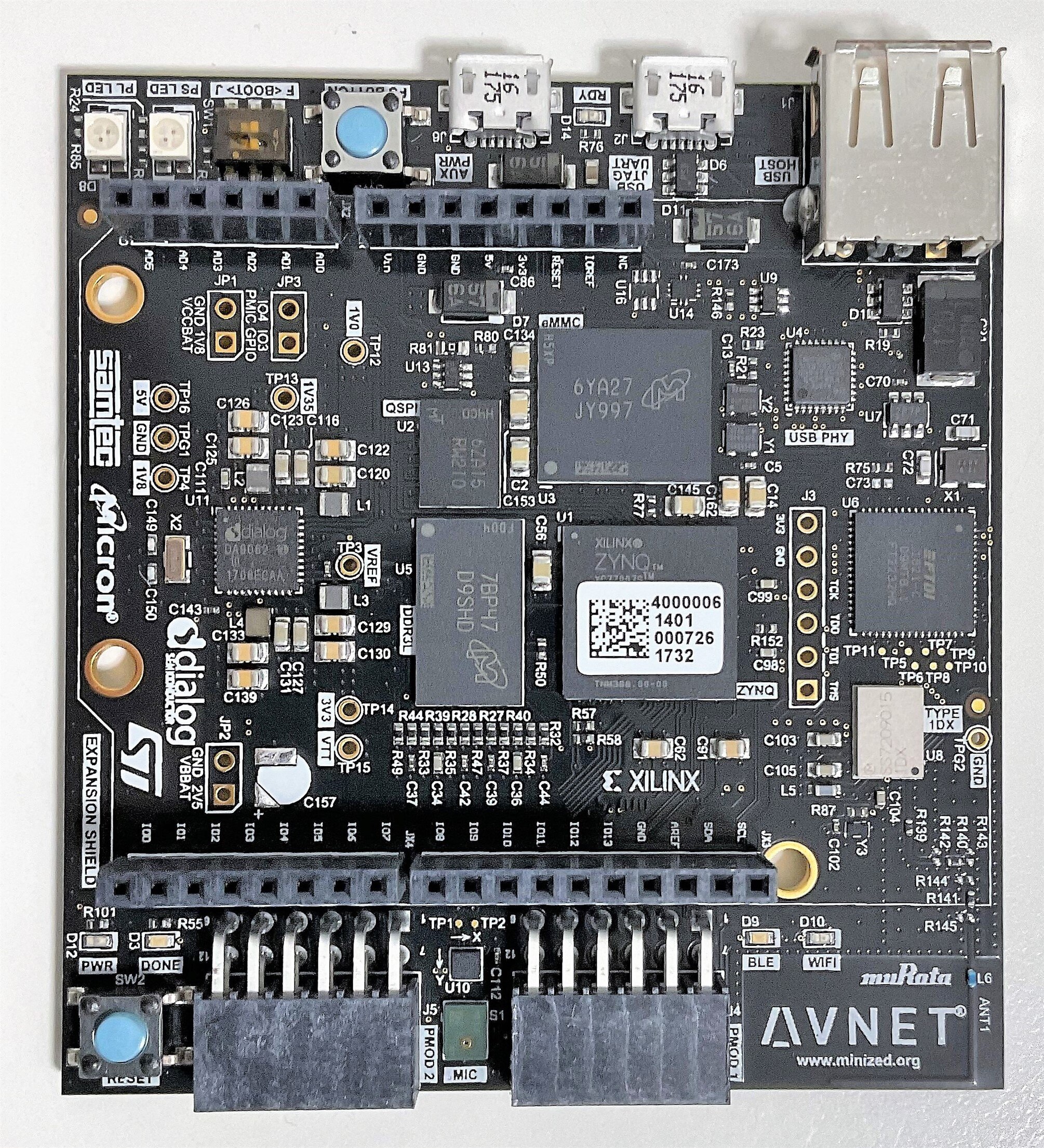
On the other hand, the Zynq-7Z007S is an integrated system-on-chip (SoC) that combines a single-core ARM Cortex-A9 processor with an Artix 7 FPGA fabric on a single chip. It offers a balance between performance and resource utilization, making it suitable for various applications. The integration of an ARM processor with the FPGA fabric provides a seamless interaction between hardware and software.
Artix 7 FPGAs are designed for transceiver optimization and highest DSP bandwidth.
Avnet Minized AMD Zynq-7Z007S
While the MicroBlaze software processor provides flexibility and cost-effectiveness specifically for FPGA designs, the Zynq-7Z007S offers a more integrated solution with a dedicated ARM processor and FPGA fabric on a single chip.
Spartan-7 FPGA Microblaze Original Design
The original design, based on the Spartan-7 FPGA and MicroBlaze soft processor, was implemented using a Bare Metal application on the Digilent Arty S7-50 development board. Two external modules designed by Digilent, the PMOD Hygro and PMOD OLED modules, were utilized as shown in the image.
You can read the whole story in my participation in the "7 Ways to Leave Your Spartan-6 FPGA" program: Arty S7 50 Rapid Prototyping - Environmental Monitor
Digilent Arty S7-50 AMD Spartan-7
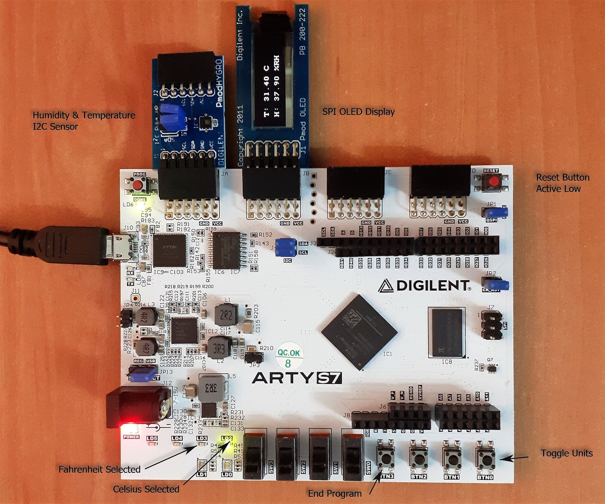
In addition to the PMOD modules connected to the PMOD connectors on the Arty S7 board, the design incorporated twoLEDs to indicate whether the temperature is displayed in Celsius or Fahrenheit. A push button was used to toggle between displaying the temperature in one thermal scale to the other. The OLED display featured a two-line interface, showcasing the ambient temperature and relative humidity percentage.
The program running on the MicroBlaze soft processor was developed in C, leveraging the drivers provided by Digilent. This allowed for seamless communication and control of the PMOD modules, enabling the display of temperature and humidity information on the OLED display.
Migrating the system between two differents Spartan-7 development boards
This design was easily ported to the AMD SP701 development board presented above, with a slight modification. Instead of using the PMOD OLED module, the HDMI output of the board was utilized, along with a design created in Vitis HLS (High-Level Synthesis). More on this in the following AMD SP701 - Experimenting with Sensor Fusion Design Challenge blog: Sensor Fusion for Firefighters. Compass and Environmental HUD monitor with the Spartan-7
The portability of the solution between two FPGAs of the same family was complete. There were no added problems when porting the solution from one board to another. In this case, both designs were supported by the Microblaze soft processor. Let's see what happens when we try to make the same application in a design that uses the Arm Cortex-A9 processor included in the Zynq.
Migrating from the MicroBlaze/Spartan-7 to the Zynq/Artix-7
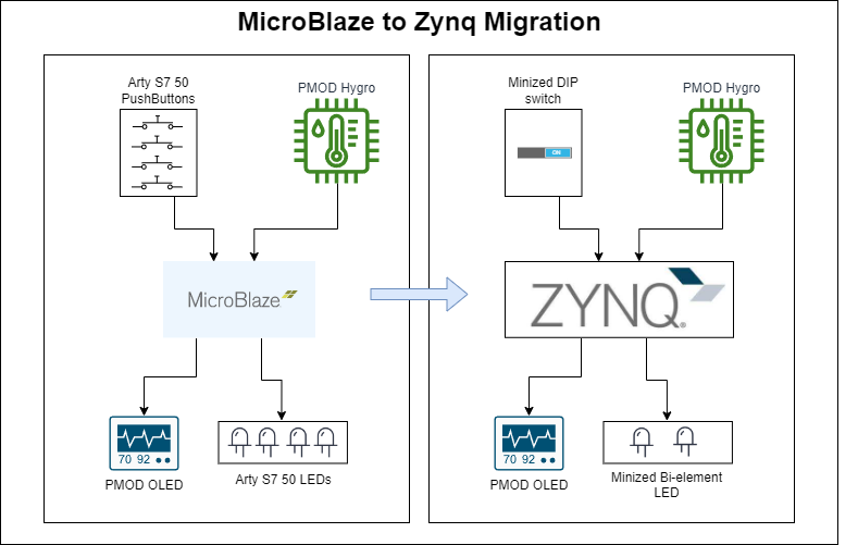
As shown in the diagram we want to convert the system on the left, an environmental monitor solution based on the MicroBlaze soft processor, into a solution based on the Minized Zynq's ARM Cortex-A9 processor.
In addition to the change of the processor we will have to take into account that the Minized board does not have the four pushbuttons that the Digilent Arty S7 50 board has nor the four indicator LEDs. We will complete that part of the hardware with the Programmable Logic Switch and the Programmable Logic Bi-element LED of the Minized
The Pmod Sensor and Actuator Modules
A brief overview of the Digilent Pmod modules that we are using. More about the modules in the blogs referred to above.
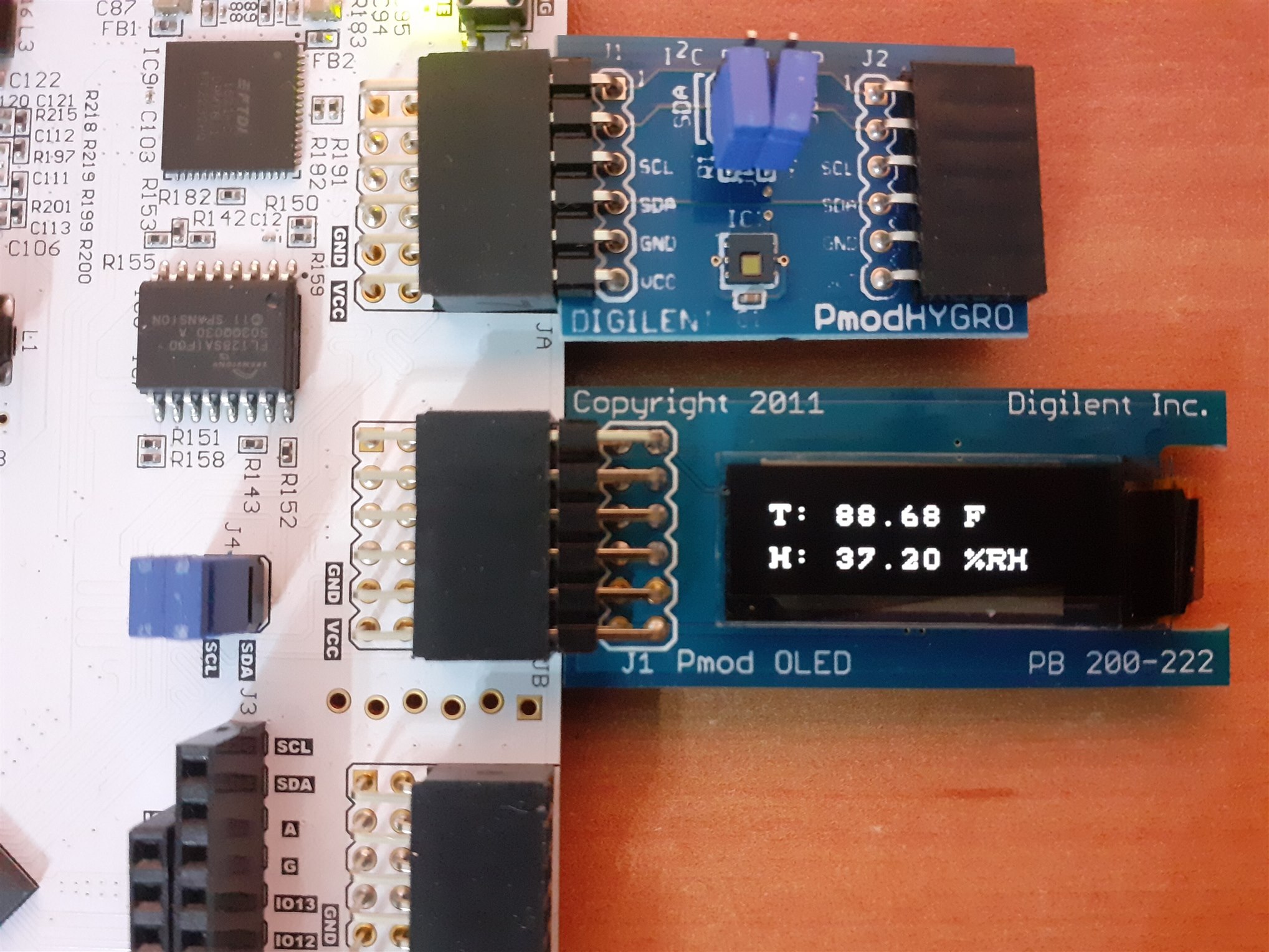
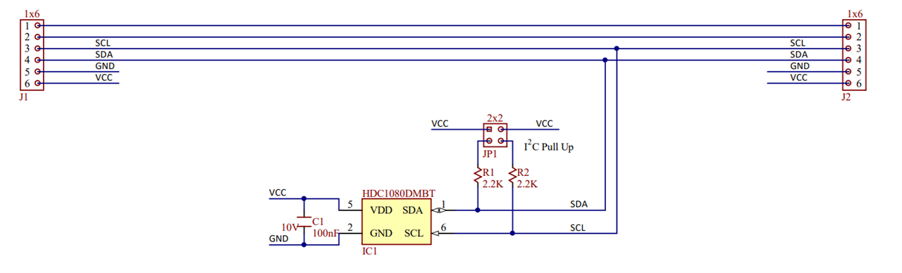
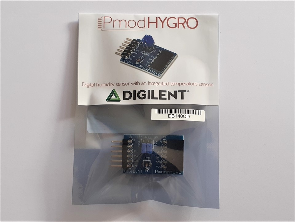
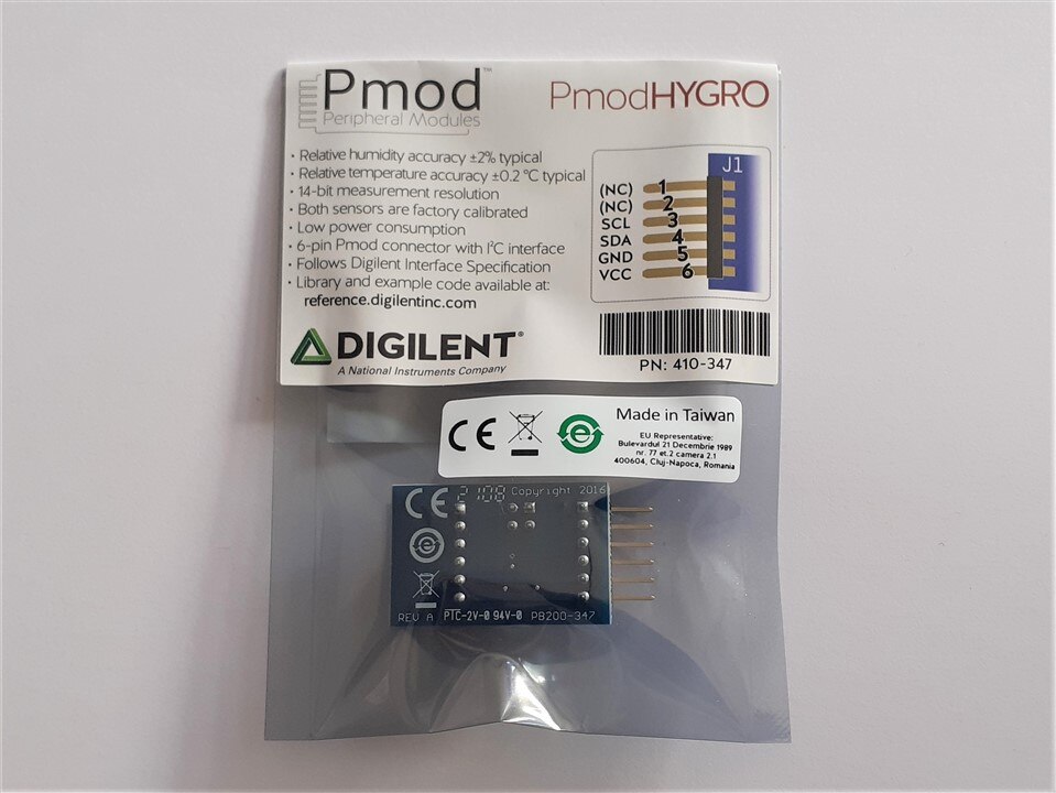
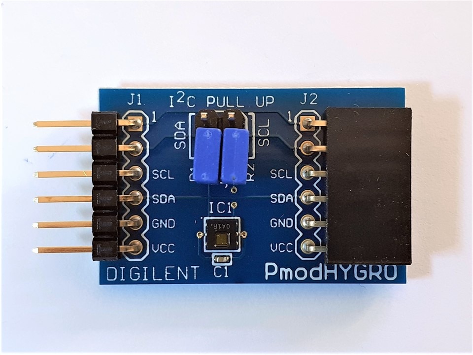
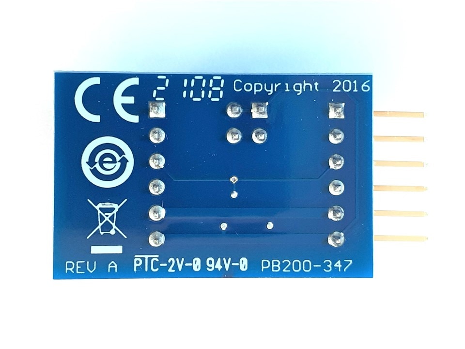
Digilent PmodHYGRO
The Digilent Pmod HYGRO is a relative humidity sensor with an integrated temperature sensor for highly accurate measurements at low power. With the TI HDC1080, we can determine the relative humidity of the environment with up to 14 bits of resolution.
References:
| {gallery}Digilent PmodHYGRO |
|---|
|
Digilent PmodHYGRO - Unboxing |
|
Digilent PmodHYGRO - Unboxing |
|
Digilent PmodHYGRO - Front |
|
Digilent PmodHYGRO - BACK |
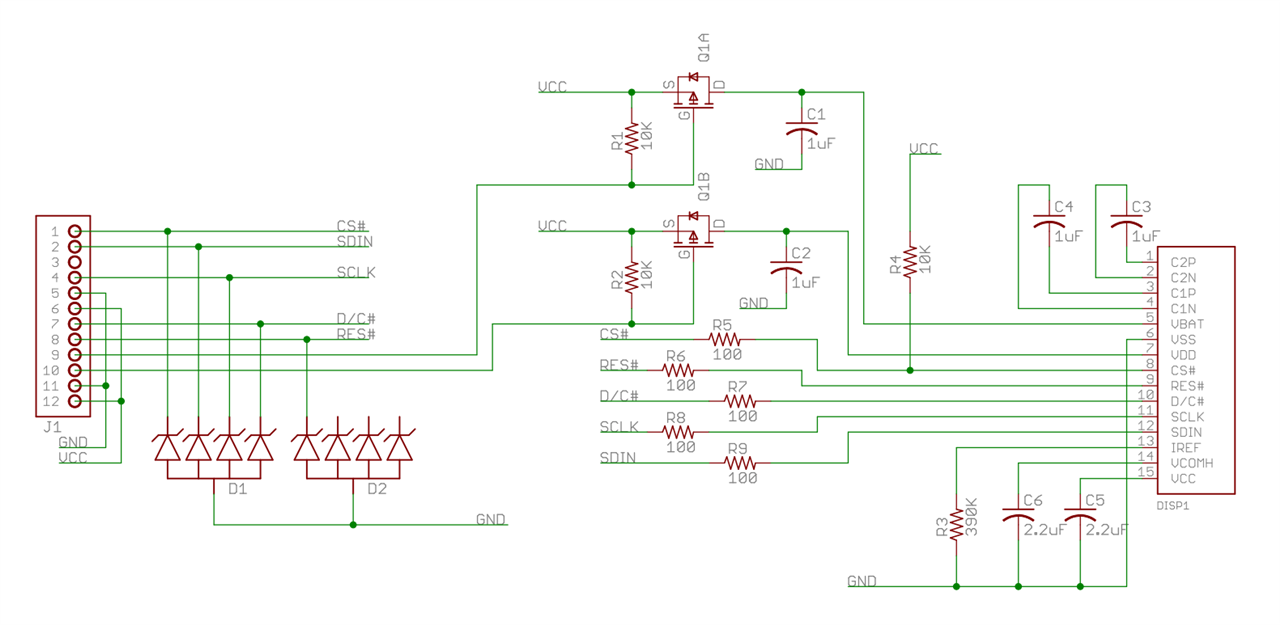
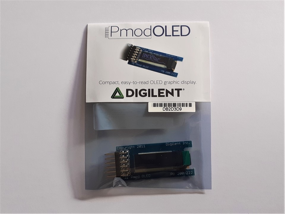
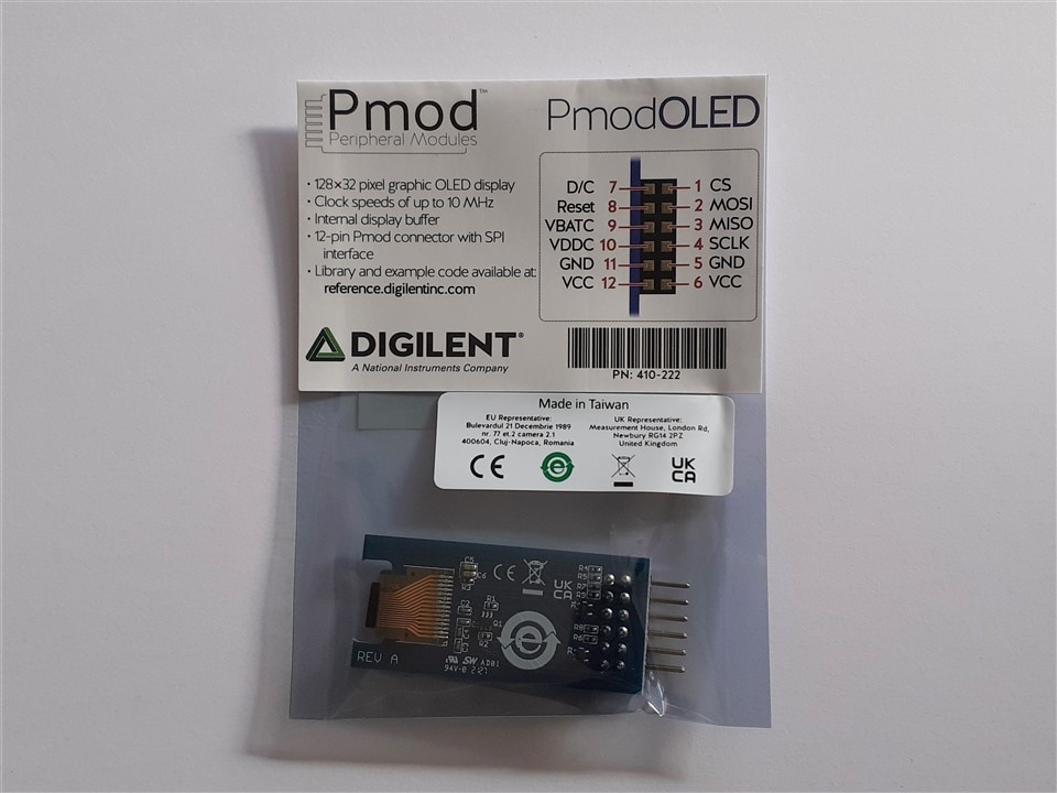
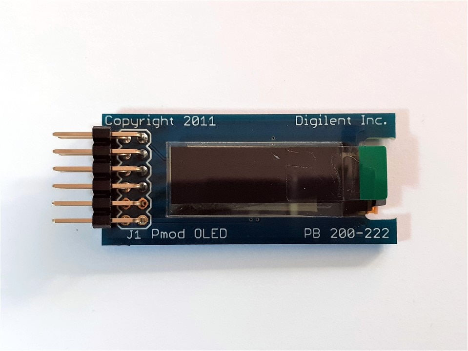
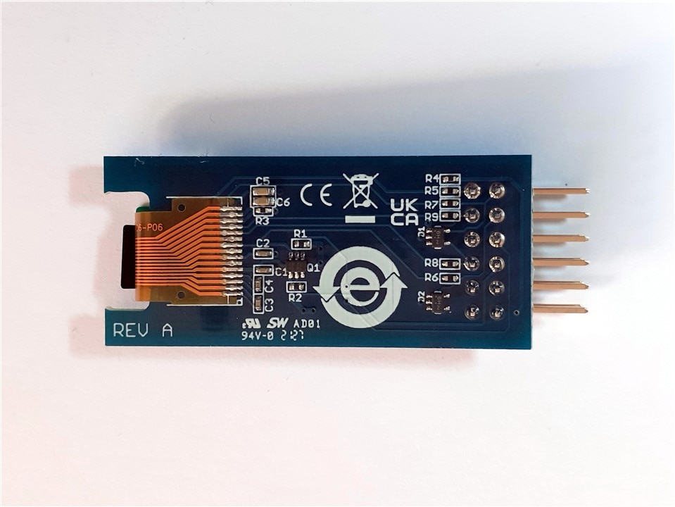
Digilent PmodOLED
The Digilent Pmod OLED (Revision A) is an organic LED module with a 128×32 pixel display. Primary IC SSD1306
References:
| {gallery}Digilent PmodOLED |
|---|
|
Digilent PmodOLED unboxing |
|
Digilent PmodOLED unboxing |
|
Digilent PmodOLED Front |
|
Digilent PmodOLED Back |
Designing the new hardware with the Zynq
To design the hardware to closely resemble the original design using the MicroBlaze, I will utilize the two Pmods connectors on the Avnet Minized.
Original Microblaze Based Version Block Design
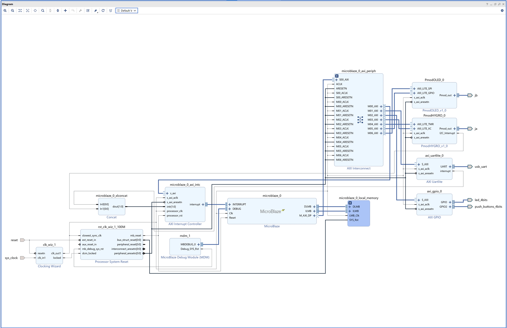
To replicate the design using the Zynq, I will utilize the same intellectual property (IP) blocks provided by Digilent for both the PMOD OLED and PMOD Hygro modules, which were used in the original design with MicroBlaze.
By incorporating the Digilent-provided IP blocks for both the PMOD OLED and PMOD Hygro modules, I will ensure that the Zynq replicates the same functionality as the original design with MicroBlaze. These IP blocks abstract the low-level communication details, making it easier to interface with the modules and achieve the desired functionality. Digilent provides software drivers compatible with both Microblaze and ARM Zynq processors.
For the PMOD OLED module, I will include the Digilent PMOD OLED IP block, which provides the necessary functionality for SPI communication with the OLED display. This IP block will handle the low-level details of the SPI protocol, allowing the Zynq to communicate with the OLED module seamlessly. By connecting it to the GPIO pins assigned to the PMOD OLED module, I will enable the Zynq to control the OLED display.
For the PMOD Hygro module, I will include the Digilent PMOD Hygro IP block, which facilitates I2C communication with the humidity and temperature sensors on the module. This IP block will handle the I2C protocol, including data transfer and address handling, simplifying the communication process. Additionally, I will configure the IP block to capture the I2C interrupt. By configuring the IP block and establishing the necessary connections, the Zynq will be able to communicate with the PMOD Hygro module via I2C and handle interrupts when required.
New Zynq Based Version Block Design
This will be the new design:
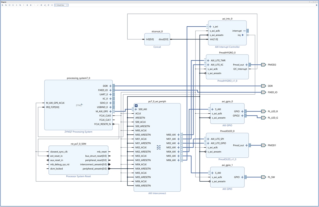
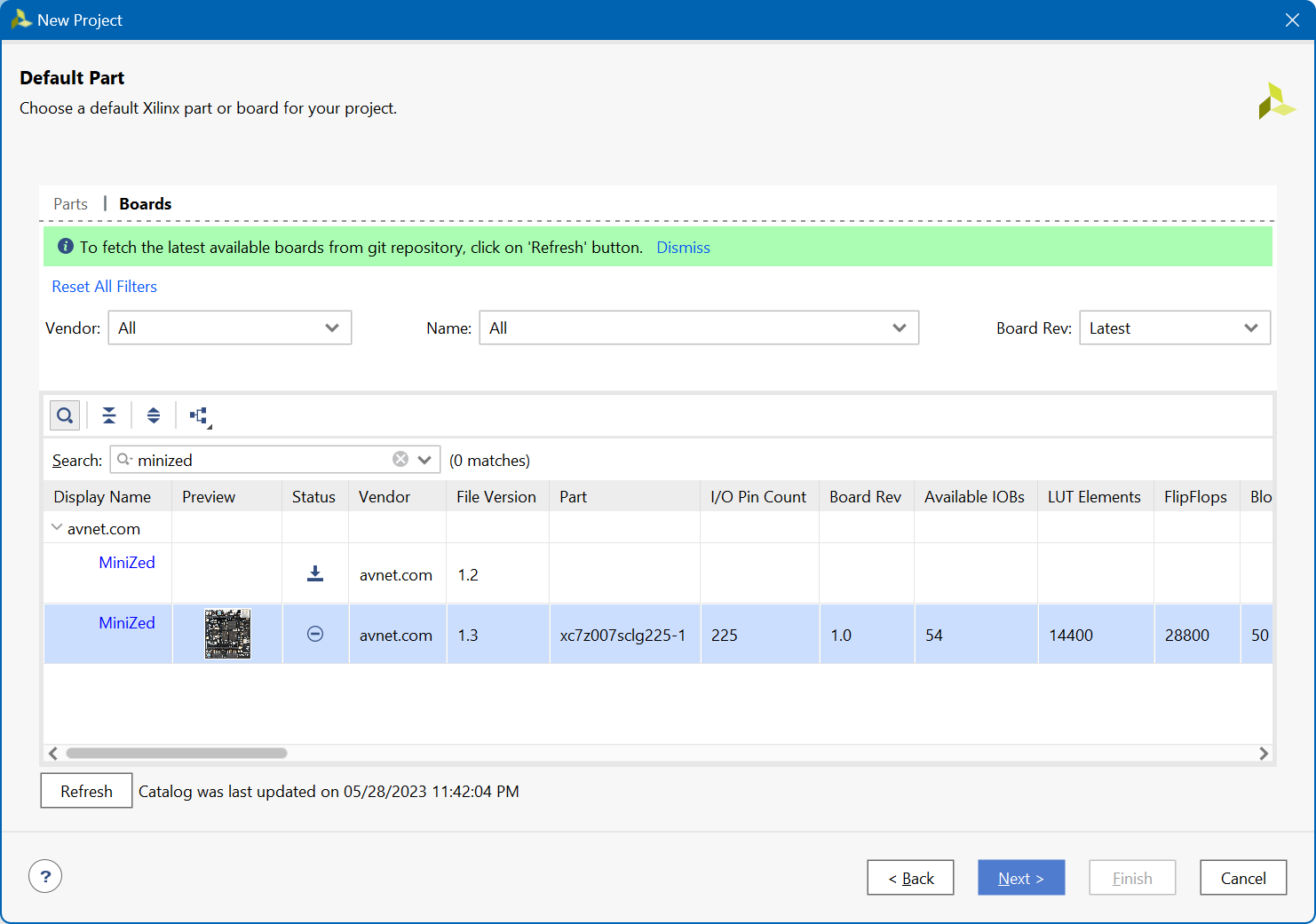
The new design incorporates an instance of the Zynq PS IP Block that allows us to configure all the necessary aspects of the Zynq, some of the features are dependent on the Avnet Zynq development board, so to facilitate our design we will start from the definitions of Minized dashboard specs created by Avnet for Vivado.
Importing Digilent Vivado IPs
Then we can download Digilent IP Blocks from Digilent's vivado-library repository: Digilent/vivado-library (github.com)
I found some problems with the Digilent drivers and Vivado 2022.2 under Windows 11. Examining the errors I found a problem with referencing wildcards in the drivers makefiles.
You can change the Makefie of the two drivers by the following ones:
Makefile for PMOD Hygro C Driver
COMPILER=
ARCHIVER=
CP=cp
COMPILER_FLAGS=
EXTRA_COMPILER_FLAGS=
LIB=libxil.a

RELEASEDIR=../../../lib
INCLUDEDIR=../../../include
INCLUDES=-I./. -I${INCLUDEDIR}

INCLUDEFILES=*.h
LIBSOURCES=$(wildcard *.c)
OUTS = *.o
OBJECTS = $(addsuffix .o, $(basename $(wildcard *.c)))
ASSEMBLY_OBJECTS = $(addsuffix .o, $(basename $(wildcard *.S)))

libs:
	@echo 'Compiling Pmod Hygro'
	$(COMPILER) $(COMPILER_FLAGS) $(EXTRA_COMPILER_FLAGS) $(INCLUDES) $(LIBSOURCES)
	$(ARCHIVER) -r ${RELEASEDIR}/${LIB} ${OBJECTS} ${ASSEMBLY_OBJECTS}
	make clean

include:
	${CP} $(INCLUDEFILES) $(INCLUDEDIR)

clean:
	rm -rf ${OBJECTS} ${ASSEMBLY_OBJECTS}
Makefile for the PMOD OLED C Driver
COMPILER=
ARCHIVER=
CP=cp
COMPILER_FLAGS=
EXTRA_COMPILER_FLAGS=
LIB=libxil.a

RELEASEDIR=../../../lib
INCLUDEDIR=../../../include
INCLUDES=-I./. -I${INCLUDEDIR}

INCLUDEFILES=*.h
LIBSOURCES=$(wildcard *.c)
OUTS = *.o
OBJECTS = $(addsuffix .o, $(basename $(wildcard *.c)))
ASSEMBLY_OBJECTS = $(addsuffix .o, $(basename $(wildcard *.S)))

libs:
	@echo 'Compiling PMOD_oled'
	$(COMPILER) $(COMPILER_FLAGS) $(EXTRA_COMPILER_FLAGS) $(INCLUDES) $(LIBSOURCES)
	$(ARCHIVER) -r ${RELEASEDIR}/${LIB} ${OBJECTS} ${ASSEMBLY_OBJECTS}
	make clean
include:
	${CP} $(INCLUDEFILES) $(INCLUDEDIR)

clean:
	rm -rf ${OBJECTS} ${ASSEMBLY_OBJECTS}
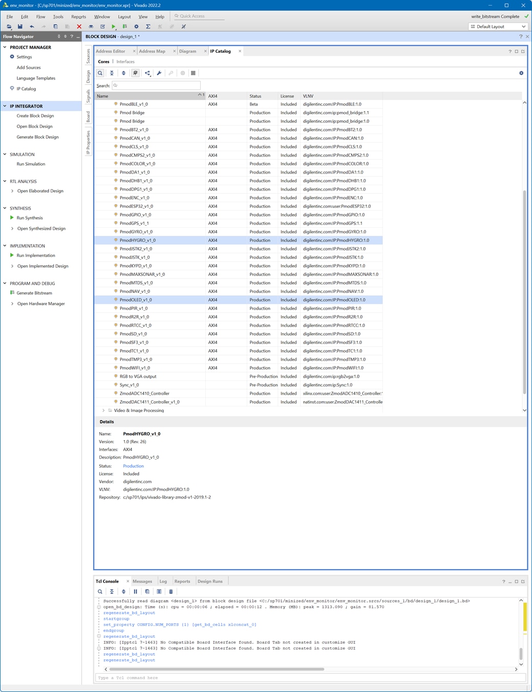
IP Catalog
Once imported they are referenced in the IP Catalog Settings ready to be instantiate.
The design uses the PmodHYGRO_v1.0 and the PmodOLED_v1.0
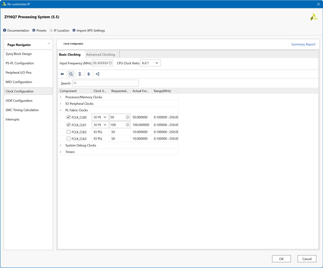
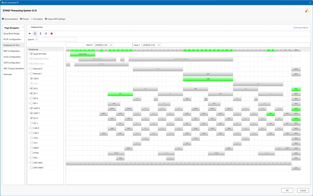
Configuring the Zynq Processing System
In the block diagram of the VIvado IP Integrator we can configure settings for our Zynq
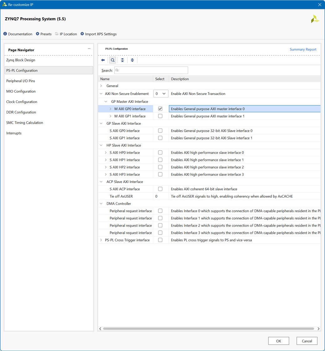
We will enable de QUAD SPI Flash Memory Interface and the AXI Master Ports. And configure a clock for the Programmable Logic.

We will use the FCLK_CLK0 configured to 50 MHz to provide synchronization to the two PMOD modules interfaces.
We created and reserved the 100 MHz clock for future use, it will not be used in this design.
We enable the 2 UARTs, one will be used for debugging/printing to console.
As we are controlling the PMODs through AXI Lite interfaces we will need to enable a General purpose AXI Master Interface
Finding package PINs from the schematics
To configure the physical PMOD connectors, we can search for xdc files on Google or more easily find them in the schematics.
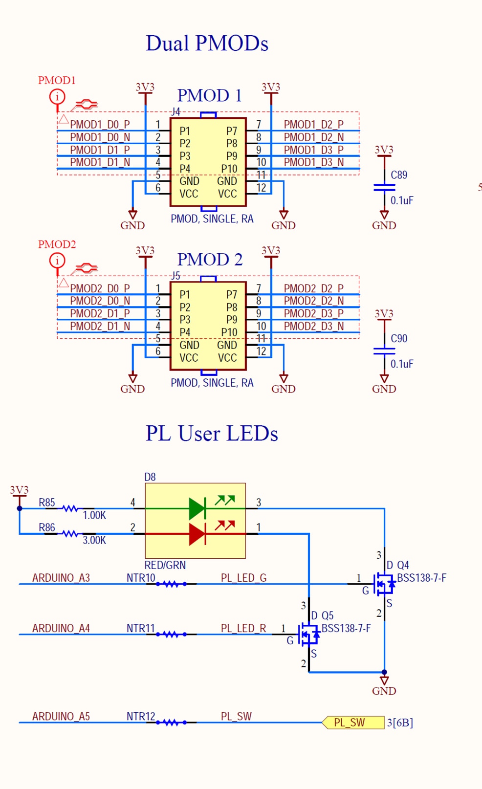
Starting with the PMOD connectors, we follow the diagram until we find the pins of the package to which they are connected.
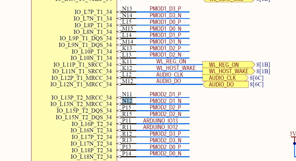
Using the I/O Ports Editor form the Implemented Design section we can configure the needed ports to the package PINs
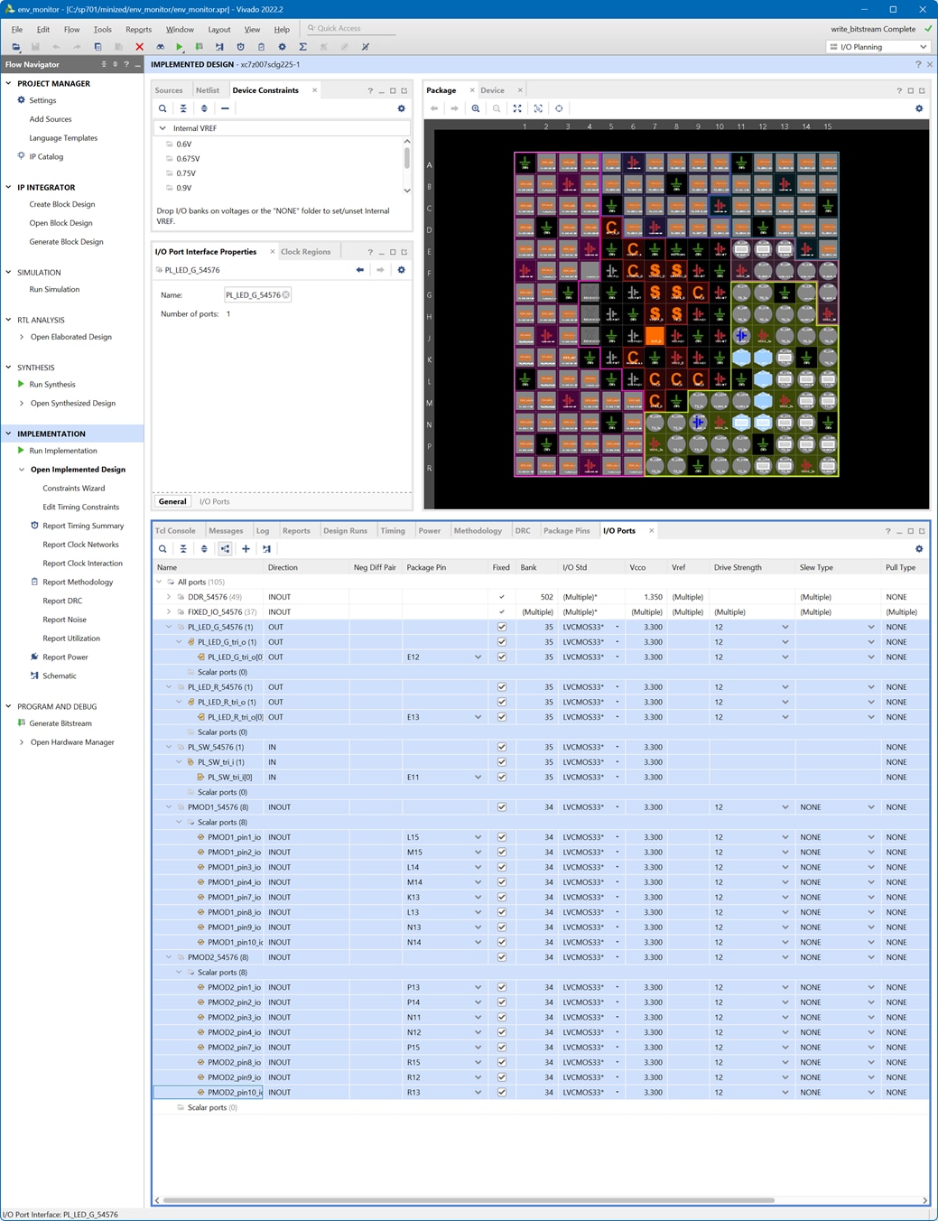
Finally we get an XDC constraints file with the configured ports
#######################################################################
# PL_SW_1
#######################################################################

set_property IOSTANDARD LVCMOS33 [get_ports {PL_SW_tri_i[0]}]
set_property PACKAGE_PIN E11 [get_ports {PL_SW_tri_i[0]}]

#######################################################################
# PL_LED_G
#######################################################################

set_property IOSTANDARD LVCMOS33 [get_ports {PL_LED_G_tri_o[0]}]
set_property PACKAGE_PIN E12 [get_ports {PL_LED_G_tri_o[0]}]

#######################################################################
# PL_LED_R
#######################################################################

set_property IOSTANDARD LVCMOS33 [get_ports {PL_LED_R_tri_o[0]}]
set_property PACKAGE_PIN E13 [get_ports {PL_LED_R_tri_o[0]}]

#######################################################################
# Pmod #2
#######################################################################

set_property IOSTANDARD LVCMOS33 [get_ports PMOD1_pin1_io]
set_property PACKAGE_PIN L15 [get_ports PMOD1_pin1_io]

set_property IOSTANDARD LVCMOS33 [get_ports PMOD1_pin2_io]
set_property PACKAGE_PIN M15 [get_ports PMOD1_pin2_io]

set_property IOSTANDARD LVCMOS33 [get_ports PMOD1_pin3_io]
set_property PACKAGE_PIN L14 [get_ports PMOD1_pin3_io]

set_property IOSTANDARD LVCMOS33 [get_ports PMOD1_pin4_io]
set_property PACKAGE_PIN M14 [get_ports PMOD1_pin4_io]

set_property IOSTANDARD LVCMOS33 [get_ports PMOD1_pin7_io]
set_property PACKAGE_PIN K13 [get_ports PMOD1_pin7_io]

set_property IOSTANDARD LVCMOS33 [get_ports PMOD1_pin8_io]
set_property PACKAGE_PIN L13 [get_ports PMOD1_pin8_io]

set_property IOSTANDARD LVCMOS33 [get_ports PMOD1_pin9_io]
set_property PACKAGE_PIN N13 [get_ports PMOD1_pin9_io]

set_property IOSTANDARD LVCMOS33 [get_ports PMOD1_pin10_io]
set_property PACKAGE_PIN N14 [get_ports PMOD1_pin10_io]


#######################################################################
# Pmod #2
#######################################################################

set_property IOSTANDARD LVCMOS33 [get_ports PMOD2_pin1_io]
set_property PACKAGE_PIN P13 [get_ports PMOD2_pin1_io]

set_property IOSTANDARD LVCMOS33 [get_ports PMOD2_pin2_io]
set_property PACKAGE_PIN P14 [get_ports PMOD2_pin2_io]

set_property IOSTANDARD LVCMOS33 [get_ports PMOD2_pin3_io]
set_property PACKAGE_PIN N11 [get_ports PMOD2_pin3_io]

set_property IOSTANDARD LVCMOS33 [get_ports PMOD2_pin4_io]
set_property PACKAGE_PIN N12 [get_ports PMOD2_pin4_io]

set_property IOSTANDARD LVCMOS33 [get_ports PMOD2_pin7_io]
set_property PACKAGE_PIN P15 [get_ports PMOD2_pin7_io]

set_property IOSTANDARD LVCMOS33 [get_ports PMOD2_pin8_io]
set_property PACKAGE_PIN R15 [get_ports PMOD2_pin8_io]

set_property IOSTANDARD LVCMOS33 [get_ports PMOD2_pin9_io]
set_property PACKAGE_PIN R12 [get_ports PMOD2_pin9_io]

set_property IOSTANDARD LVCMOS33 [get_ports PMOD2_pin10_io]
set_property PACKAGE_PIN R13 [get_ports PMOD2_pin10_io]
Then generate the bitstream programming file and export hardware (.xsa file) including the generated bitstream.
Programming the software from AMD Vitis
Now we can create a new platform project from the exported .xsa
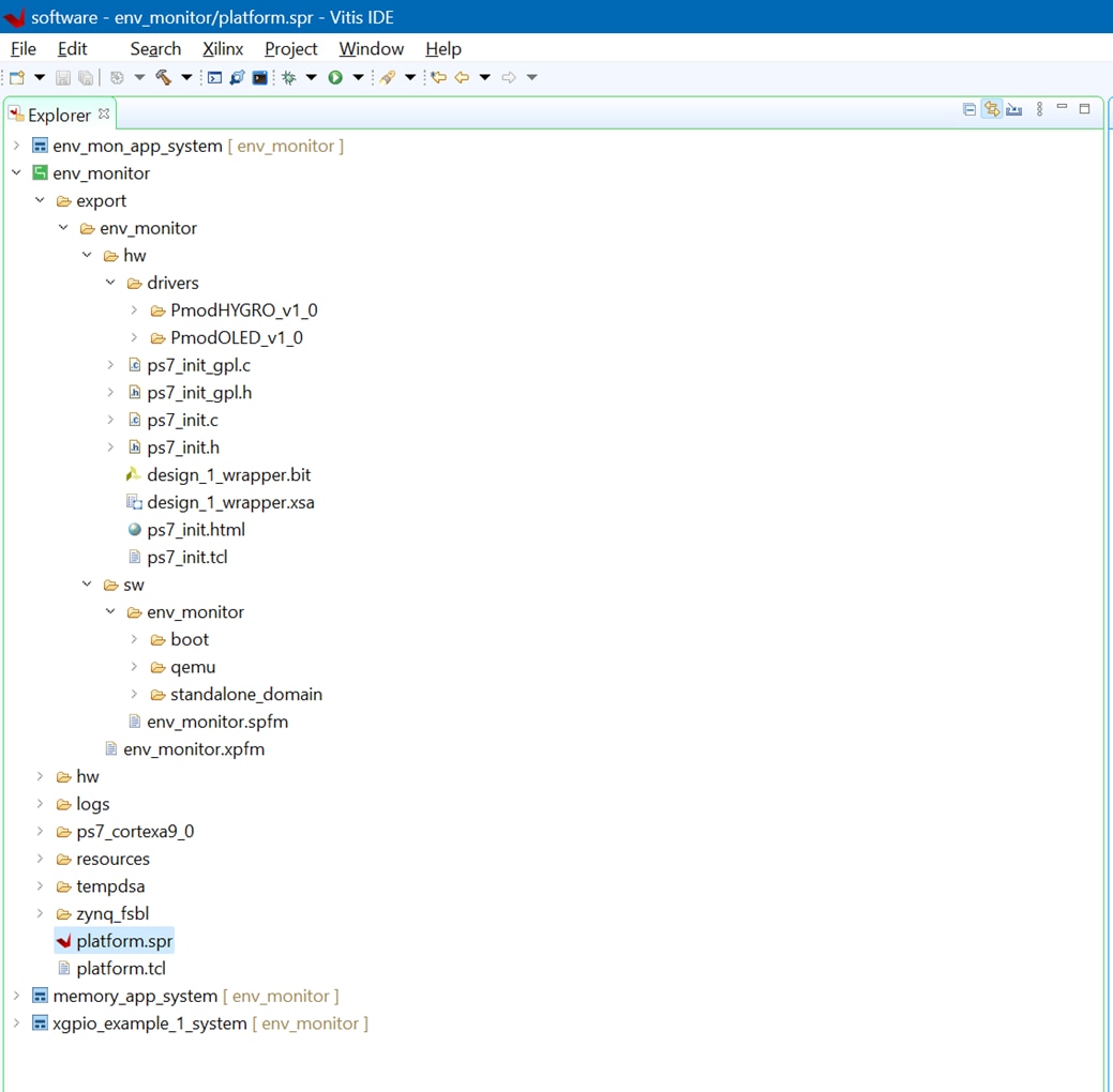
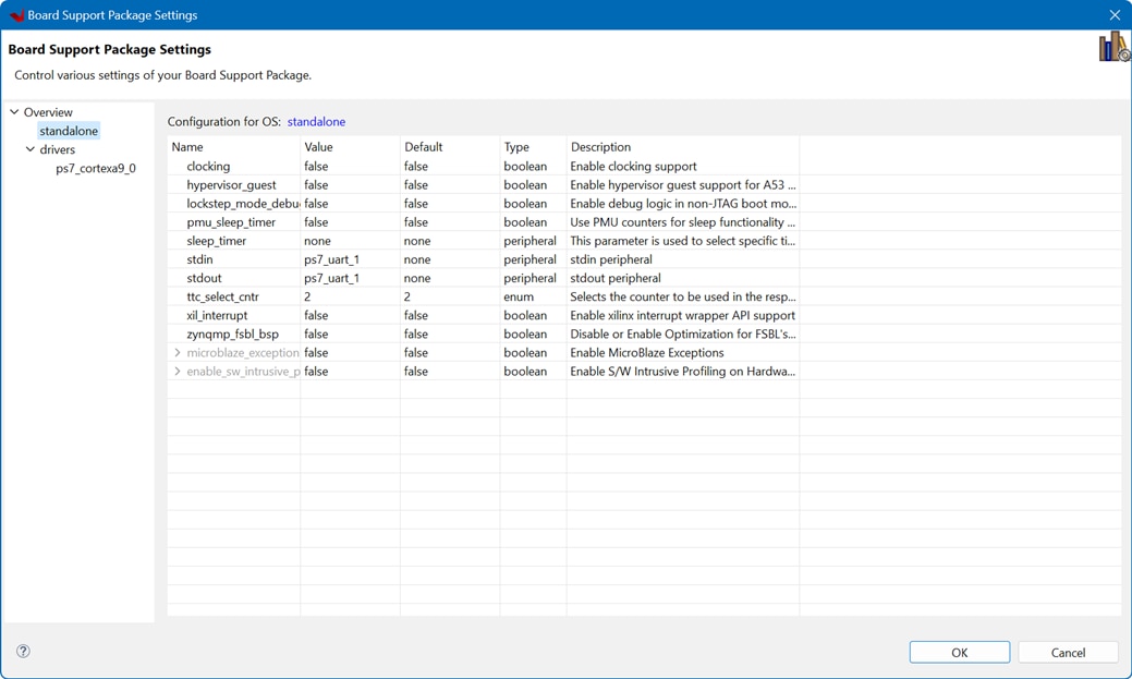
Set the stdin and stdout variables to the uart1 of the PS for debugging purposes under the Board Support Package Settings
And create a new Empty Application Project using that Hardware Platform Project.
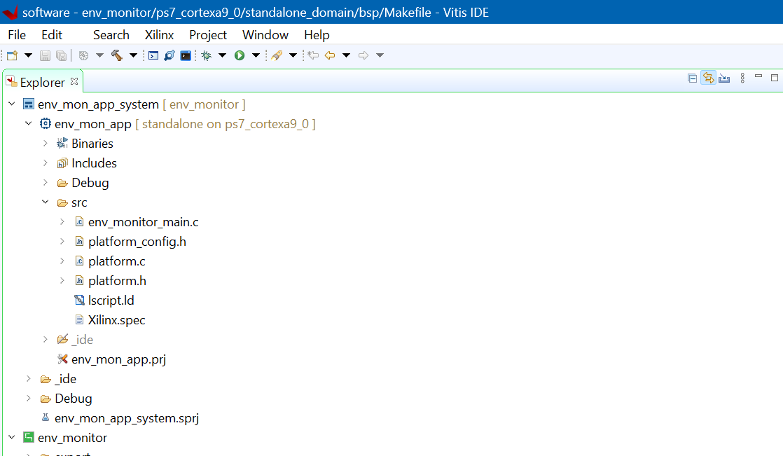
Then import the C Application code from the previous design and change only the references to the xparameters.h That's all!
// Get device IDs from xparameters.h#define BTN_ID XPAR_AXI_GPIO_1_DEVICE_ID#define LED_ID XPAR_AXI_GPIO_0_DEVICE_ID#define BTN_CHANNEL 1#define LED_CHANNEL 1
/******************************************************************************/
/*                                                                            */
/* env_monitor_main.c -- Environmental Monitor. Temperature / Humidity        */
/*  PmodOLED IP + PmodHYGRO                                                   */
/*                                                                            */
/******************************************************************************/
/* Author: Enrique Albertos                                                   */
/* 2022-2023 Public Domain                                                    */
/******************************************************************************/
/* File Description:                                                          */
/*                                                                            */
/* This project initializes and uses the PmodOLED and the PmodHYGRO to        */
/* display temperature and humidity values.                                   */
/* Temperature and humidity data are captured from the I2C connection and     */
/* displayed over the serial connection and on the OLED display once per      */
/* second.                                                                    */
/* This application configures UART 16550 to Baud rate 9600. PS7 UART (Zynq)  */
/* is not initialized by this application, since bootrom/bsp configures it to */
/* Baud rate 115200.                                                          */
/*                                                                            */
/*    UART TYPE   BAUD RATE                                                   */
/*    uartns550   9600                                                        */
/*    uartlite    Configurable only in HW design                              */
/*    ps7_uart    115200 (configured by bootrom/bsp)                          */
/*                                                                            */
/******************************************************************************/
/* Revision History:                                                          */
/*                                                                            */
/*    11/06/2022 Enrique Albertos:   Created w/ Vivado 2021.1                 */
/*    08/06/2023 Enrique Albertos:   Adapted to Avnet Minized Vivado 2022.2   */
/*                                                                            */
/******************************************************************************/
/* Baud Rates:                                                                */
/*                                                                            */
/*    Microblaze: 9600 or what was specified in UARTlite core                 */
/*    Zynq: 115200                                                            */
/*                                                                            */
/******************************************************************************/

/* ------------------------------------------------------------ */
/*                  Include File Definitions                    */
/* ------------------------------------------------------------ */

#include "PmodOLED.h"
#include "PmodHYGRO.h"
#include "sleep.h"
#include "xil_cache.h"
#include "xil_printf.h"
#include "xparameters.h"
#include "xgpio.h"
#include "xil_types.h"

#ifdef __MICROBLAZE__
#define TIMER_FREQ_HZ XPAR_CPU_M_AXI_DP_FREQ_HZ
#else
#define TIMER_FREQ_HZ 100000000
#endif

/* ------------------------------------------------------------ */
/*                  Global Variables                            */
/* ------------------------------------------------------------ */

PmodOLED myOled;
PmodHYGRO myHygro;

/* ------------------------------------------------------------ */
/*                  Forward Declarations                        */
/* ------------------------------------------------------------ */

void DemoInitialize();
void DemoRun();
void DemoCleanup();
void EnableCaches();
void DisableCaches();
void OLED_putFloatVariable(PmodOLED *InstancePtr, int xch, int ych, char * head,
		float value, char * tail);

// To change between PmodOLED and OnBoardOLED is to change Orientation
const u8 orientation = 0x0; // Set up for Normal PmodOLED(false) vs normal
// Onboard OLED(true)
const u8 invert = 0x0; // true = whitebackground/black letters
// false = black background /white letters

#define BTN_MASK 0b1111
#define LED_MASK 0b1111
#define BTN1_MASK 0b0001
#define BTN2_MASK 0b0010
#define BTN3_MASK 0b0100
#define BTN4_MASK 0b1000
#define LED1_MASK 0b0001
#define LED2_MASK 0b0010
#define LED3_MASK 0b0100
#define LED4_MASK 0b1000
#define CELSIUS_LED LED1_MASK
#define FAHRENHEIT_LED LED1_MASK

// Get device IDs from xparameters.h
#define BTN_ID XPAR_AXI_GPIO_1_DEVICE_ID
#define LED_ID XPAR_AXI_GPIO_0_DEVICE_ID
#define BTN_CHANNEL 1
#define LED_CHANNEL 1

// can use a push button or an slide switch to toggle C/F
// #define __MINIZED__ 1

XGpio_Config *cfg_ptr;
XGpio led_device, btn_device;


/* ------------------------------------------------------------ */
/*                  Function Definitions                        */
/* ------------------------------------------------------------ */

int main() {
	DemoInitialize();
	DemoRun();
	DemoCleanup();

	return 0;
}

void DemoInitialize() {
	EnableCaches();

	xil_printf("HYGRO Init Started\n\r");
	HYGRO_begin(&myHygro,
	XPAR_PMODHYGRO_0_AXI_LITE_IIC_BASEADDR, 0x40, // Chip address of PmodHYGRO IIC
			XPAR_PMODHYGRO_0_AXI_LITE_TMR_BASEADDR,
			XPAR_PMODHYGRO_0_DEVICE_ID,
			TIMER_FREQ_HZ // Clock frequency of AXI bus, used to convert timer data
			);
	xil_printf("HYGRO Init Done\n\r");

	xil_printf("OLED Init Started\n\r");
	OLED_Begin(&myOled, XPAR_PMODOLED_0_AXI_LITE_GPIO_BASEADDR,
	XPAR_PMODOLED_0_AXI_LITE_SPI_BASEADDR, orientation, invert);
	xil_printf("OLED Init Done\n\r");

	// Initialize LED Device
	cfg_ptr = XGpio_LookupConfig(LED_ID);
	XGpio_CfgInitialize(&led_device, cfg_ptr, cfg_ptr->BaseAddress);

	// Initialize Button Device
	cfg_ptr = XGpio_LookupConfig(BTN_ID);
	XGpio_CfgInitialize(&btn_device, cfg_ptr, cfg_ptr->BaseAddress);

	// Set Button Tristate
	XGpio_SetDataDirection(&btn_device, BTN_CHANNEL, BTN_MASK);

	// Set Led Tristate
	XGpio_SetDataDirection(&led_device, LED_CHANNEL, 0);

}

/* ------------------------------------------------------------ */
/*** DemoRun()
 **
 **   Parameters:
 **      none
 **
 **   Return Value:
 **      none
 **
 **   Errors:
 **      If the demo is shut down without properly exiting, does not reinitialize
 **      properly.
 **
 **   Description:
 **      Displays Temperature each 1 second.
 **      Toggles temp units with button 1 pressed
 **      Exists when button 4 is pressed.
 **      Requires UART connection to terminal program on PC.
 */
void DemoRun() {
	long timeCounterMillis;
	u32 buttonsState;
	int button1State;
	int lastbutton1State;
	float temp_degc, hum_perrh, temp_degf;
	u8 bDegreesCelsius = 1;

	xil_printf("UART, I2C and SPI opened for Environment Monitor\n\r");
	XGpio_DiscreteWrite(&led_device, LED_CHANNEL, LED1_MASK);
	while (1) {
        // read buttons
		buttonsState = XGpio_DiscreteRead(&btn_device, BTN_CHANNEL);

        //if button 4 is pressed exit
        if(buttonsState & BTN4_MASK ) {
        	xil_printf("exiting\r\n");
        	// exit
        	break;
        }

        // check button for toggling temperature units
        button1State = buttonsState & BTN1_MASK;
		//if button 1 low to high edge
        if((button1State != lastbutton1State) && button1State && timeCounterMillis > 100) {
        	xil_printf("toggle units\r\n");
        	// toggle temp units mode

        	bDegreesCelsius = !bDegreesCelsius;

        	// change led indicator
        	if (bDegreesCelsius ) {
        		XGpio_DiscreteWrite(&led_device, LED_CHANNEL, LED1_MASK);
        	} else {
        		XGpio_DiscreteWrite(&led_device, LED_CHANNEL, LED2_MASK);
        	}
        	// force environmental data update
        	timeCounterMillis = 1001;
        }
		lastbutton1State = button1State;

        if( timeCounterMillis > 1000) {
        	timeCounterMillis = 0;
			temp_degc = HYGRO_getTemperature(&myHygro);
			temp_degf = HYGRO_tempC2F(temp_degc);
			hum_perrh = HYGRO_getHumidity(&myHygro);
			xil_printf("Temperature: %d.%02d deg F  Humidity: %d.%02d RH\n\r",
					(int) temp_degf, ((int) (temp_degf * 100)) % 100,
					(int) hum_perrh, ((int) (hum_perrh * 100)) % 100);

			// Turn automatic updating off
			OLED_SetCharUpdate(&myOled, 0);

			if(bDegreesCelsius) {
				// Display Temperature Value in Degrees Celsius
				OLED_putFloatVariable(&myOled, 1, 1, "T: ", temp_degc, " C");
			} else {
				// Display Temperature Value in Degrees Fahrenheit
				OLED_putFloatVariable(&myOled, 1, 1, "T: ", temp_degf, " F");
			}
			// Display Relative Humidity Percentage
			OLED_putFloatVariable(&myOled, 1, 3, "H: ", hum_perrh, " %RH");
			// Update display
			OLED_Update(&myOled);
        }

		usleep(1000);
		timeCounterMillis++;
	}
	xil_printf("Exiting PmodOLED Demo\n\r");
}

/*
 * Displays on the OLED a float variable with a header and a tail
 * ie T: 12.67 C
 * OLED_putFloatVariable(&myOled, 1, 1, "T: ", temp_degc, " C");
 */
void OLED_putFloatVariable(PmodOLED *InstancePtr, int xch, int ych, char * head,
		float value, char * tail) {
	OLED_SetCursor(InstancePtr, xch, ych);
	OLED_PutString(InstancePtr, head);
	OLED_PutChar(InstancePtr, ((int) value / 10) % 10 + 48);
	OLED_PutChar(InstancePtr, ((int) value) % 10 + 48);
	OLED_PutString(InstancePtr, ".");
	OLED_PutChar(InstancePtr, ((int) (value * 10)) % 10 + 48);
	OLED_PutChar(InstancePtr, ((int) (value * 100)) % 10 + 48);
	OLED_PutString(InstancePtr, tail);
}

void DemoCleanup() {
	OLED_End(&myOled);
	DisableCaches();
}

void EnableCaches() {
#ifdef __MICROBLAZE__
#ifdef XPAR_MICROBLAZE_USE_ICACHE
	Xil_ICacheEnable();
#endif
#ifdef XPAR_MICROBLAZE_USE_DCACHE
	Xil_DCacheEnable();
#endif
#endif
}

void DisableCaches() {
#ifdef __MICROBLAZE__
#ifdef XPAR_MICROBLAZE_USE_DCACHE
	Xil_DCacheDisable();
#endif
#ifdef XPAR_MICROBLAZE_USE_ICACHE
	Xil_ICacheDisable();
#endif
#endif
}
Plug and Program the Device
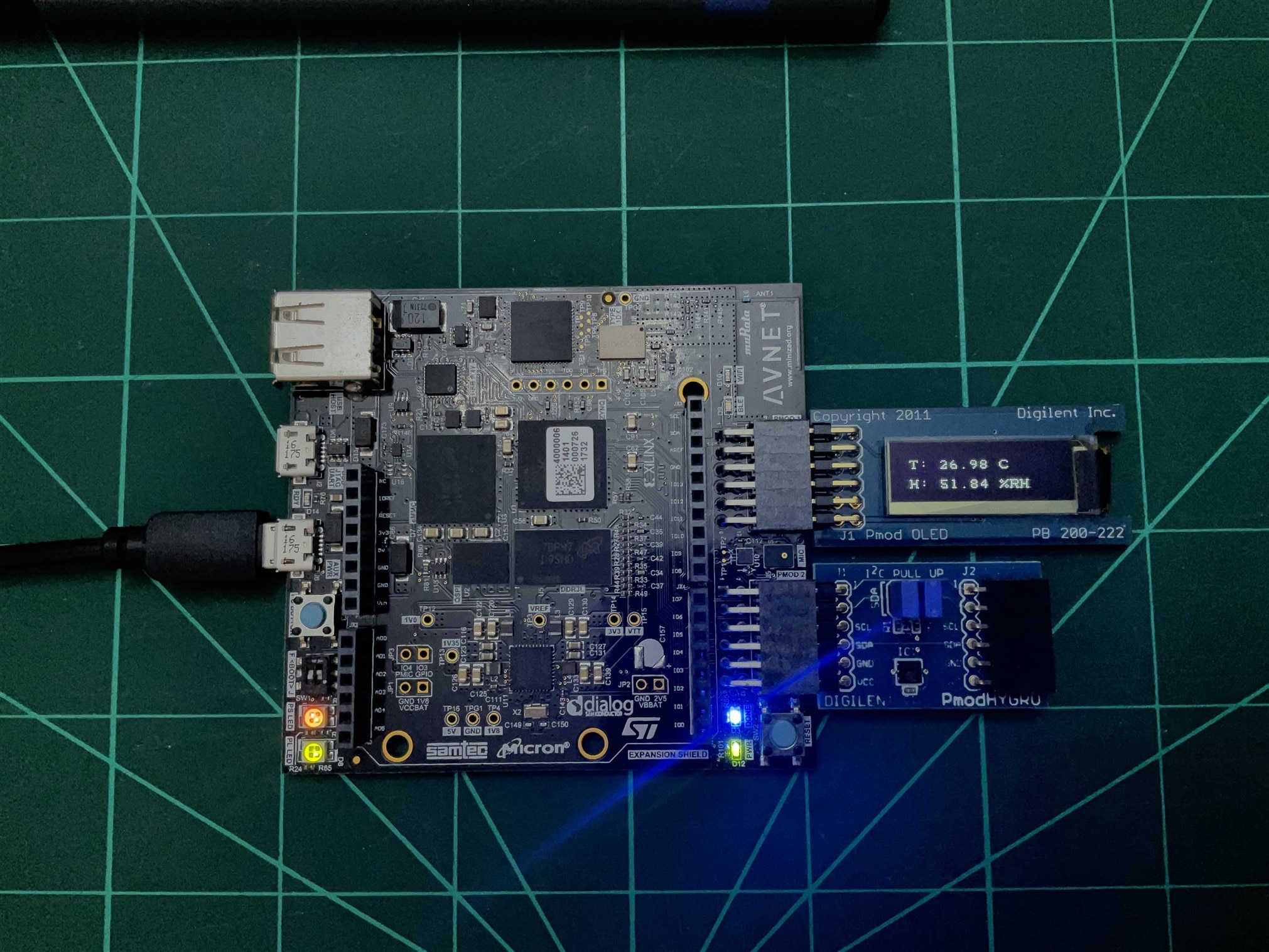
Without further changes to those due to the numbering of the AXI Lite control interfaces, the system works first time.
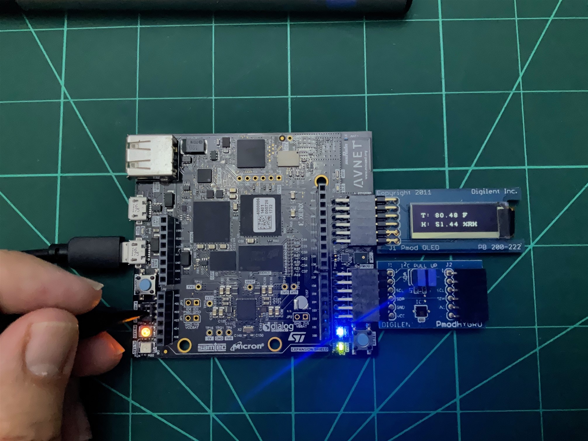
Use the DIP switch to change from Fahrenheit to Celsius scale visualization.
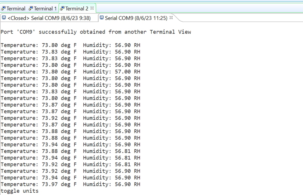
By connecting to the UART we can receive the debug lines sent by the application.
Summary
I was curious to know the degree of portability of the solutions created under the Vitis Unified Software Platform environment. I was already aware of the possibility of porting solutions between boards based on FPGAs of the same family, but I had my doubts about what would happen when migrating a development made for the Microblaze soft processor to the Zynq. I have been pleasantly surprised at how easy it has been. In the next blog we will go a step further by testing the portability of solutions that use more resources from the PL fabric.
References
- Minized Technical Documents: MiniZed - Boards - Avnet Boards Community
- My participation in the: 7 Ways to Leave Your Spartan-6 FPGA
- My participation in; AMD SP701 - Experimenting with Sensor Fusion Design Challenge
- ds190-Zynq-7000-Overview.pdf
- ds187-XC7Z010-XC7Z020-Data-Sheet.pdf
Path to Programmable III Training Blog Series
- BLOG 1: P2P3 Getting Started. Clockless Hardware Blinky on the Avnet Minized
- BLOG 2: P2P3 AMD Vitis portability and reuse. Migrating a Microblaze bare metal environmental monitor App to the Zynq architecture.
- BLOG 3: P2P3 AMD Zynq-7000 SoC XADC. External Multiplexer Mode.
- BLOG 4: P2P3 AMD Vivado Cascaded Integrator Comb (CIC) Compiler. PDM Microphone to PCM Decimation
- BLOG 5: P2P3 Wireless sensors on the Avnet Minized. Getting Started with PetaLinux
- FINAL PROJECT: AMD Zynq SoC MIDI Vintage Sound Synthesizer - Final


