


For the 7 Ways to Leave Your Spartan-6 program I am writing a series of tutorials using theArty S7 50 . In the previous blogs I did two introductory tutorials to create a simple hardware-only project and another baremetal one on a MicroBlaze softprocessor. In this blog we will build a simple environmental monitor to explore the possibilities of the Arty S7 50 board for rapid prototyping using two Pmod modules: the Pmod HYGRO and the Pmod OLED modules.
The monitor in action:
The temperature measurement unit can be adjusted by a button on the board. Unit selection is indicated by two LEDs on the board. Another button executes the completion of the main loop.

Rapid Prototyping with The Arty S7
FPGAs are especially popular for prototyping designs, due to their superior performance and affordability.
The Arty S7 provides a range of options from Arduino Shield connectors to four Pmod ports. It has a dual row Arduino® connectors to mount one of the hundreds of hardware compatible shields available, or use the Pmod ports with Digilent's pre-made Pmod IP blocks. This allows us to incorporate pre-built and tested modules and be able to immediately focus on building the first prototypes of our solution.
The Arty S7 was designed to be MicroBlaze ready and comes out of the box ready to use with the free Xilinx WebPack licensing with the Vivado Design Suite.
Tutorial Environment
For this tutorial you´ll need, Windows 10, AMD Xilinx Vivado ML 2021.1 and the following hardware
| Product Name | Manufacturer | Datasheet |
| Arty S7 50 | Digilent | Buy Now |
| PmodHYGRO | Digilent | Buy Now |
| PmodOLED | Digilent | Buy Now |
Digilent Pmod
Pmod is Digilent's defined standard for peripheral modules The Pmod modules are small I/O interface boards that allow us to expand the capabilities of microcontroller and programmable logic boards.
Pmods communicate with host boards via 6-, 8-, or 12-pin connectors that can carry multiple digital control signals, taking advantage of standard serial protocols such as SPI and I2C.
Pmods are designed to connect directly to Pmod host ports that adhere to the Digilent Pmod interface specification. Additionally, the Digilent Pmod standard establishes guidelines for form factor, communication protocols, and access to a target audience through reference manuals, code samples, user guides, and technical support.
Reference: Pmod - Digilent Reference
The Arty S7 has four Pmod connectors, some of which behave differently than others. Each Pmod connector falls into one of two categories: standard or high-speed. Also, some Pmod connectors share their connections with the
inner rows of the shield connector and should not be used at the same time as a shield that requires those pins. Table 8.1 specifies which category each Pmod falls into, whether it shares any pins with the shield connector, and also lists the FPGA pins they are connected to.
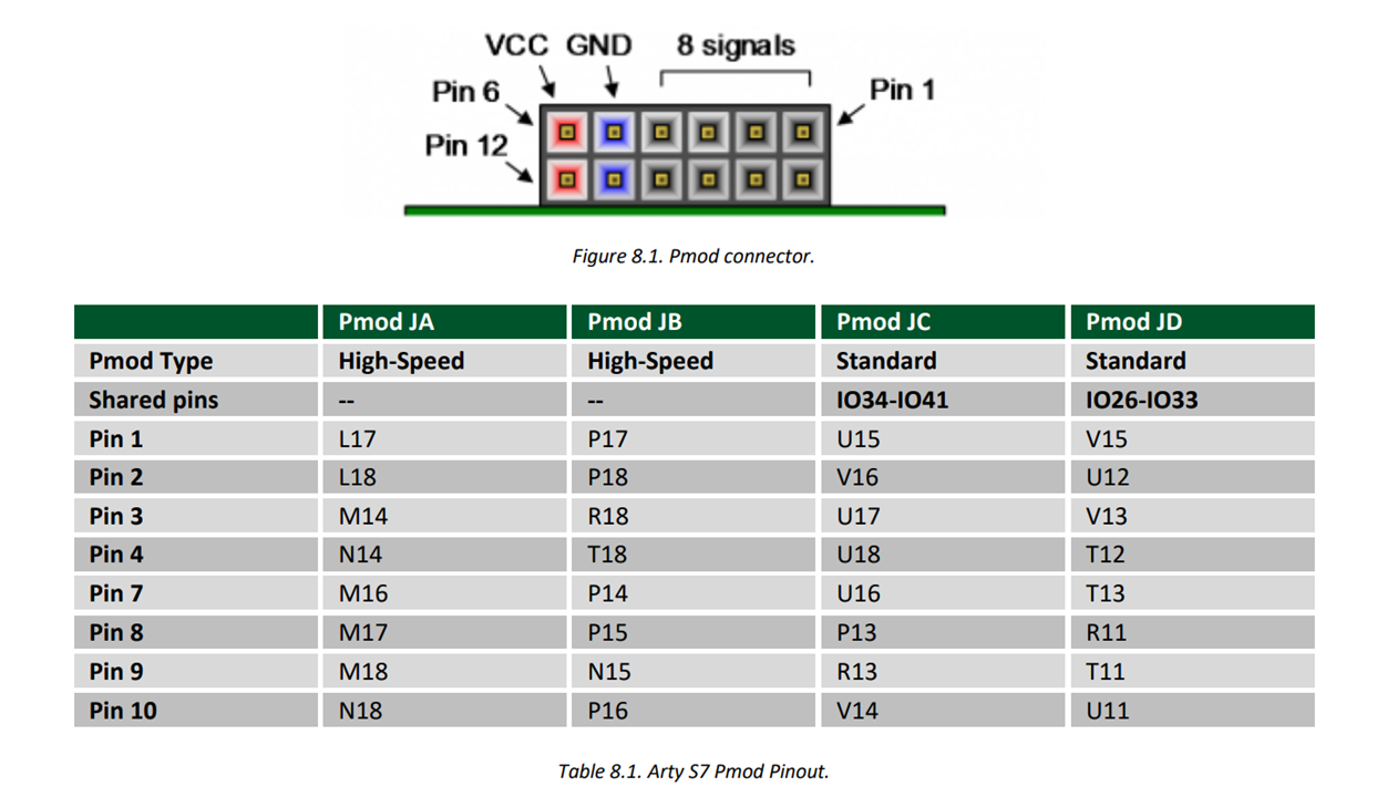
The standard Pmod connectors are connected to the FPGA via 200 Ohm series resistors. The series resistors prevent short circuits that can occur if the user accidentally drives a signal that is supposed to be used as an input.
The downside to this added protection is that these resistors can limit the maximum switching speed of the data signals. If the Pmod being used does not require high-speed access, then the standard Pmod connector should be
used to help prevent damage to the devices.
The High-speed Pmods use the standard Pmod connector but have their data signals routed as impedance matched differential pairs for maximum switching speeds. They have pads for loading resistors for added protection, but the Arty S7 ships with these loaded as 0-Ohm shunts. With the series resistors shunted, these Pmods offer no protection against short circuits, but allow for much faster switching speeds. The signals are paired to the adjacent signals in the same row: pins 1 and 2, pins 3 and 4, pins 7 and 8, and pins 9 and 10.
Pmod pins are connected to Spartan-7 FPGA pins using a 3.3V logic standard, care should be taken not to drive these pins over 3.4V.
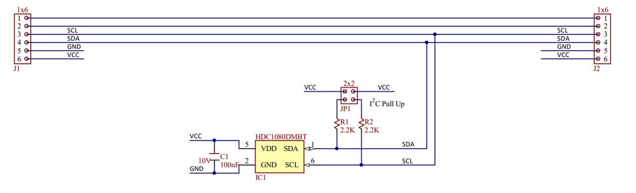
Digilent PmodHYGRO
The Digilent Pmod HYGRO is a relative humidity sensor with an integrated temperature sensor for highly accurate measurements at low power. With the TI HDC1080, we can determine the relative humidity of the environment with up to 14 bits of resolution.
References:
| {gallery}Digilent PmodHYGRO |
|---|
|
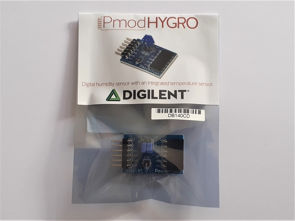
Digilent PmodHYGRO - Unboxing |
|
Digilent PmodHYGRO - Unboxing |
|
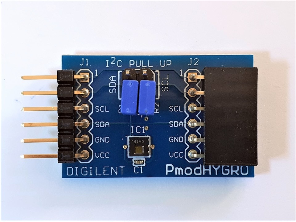
Digilent PmodHYGRO - Front |
|
Digilent PmodHYGRO - BACK |

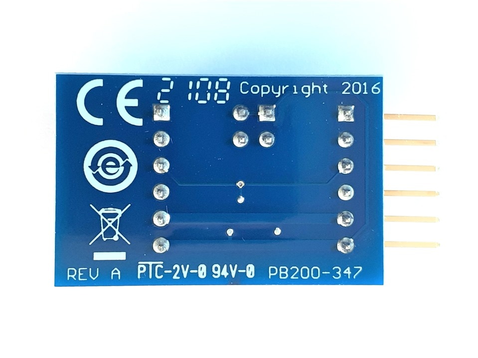
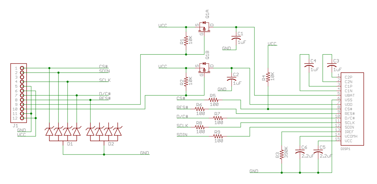
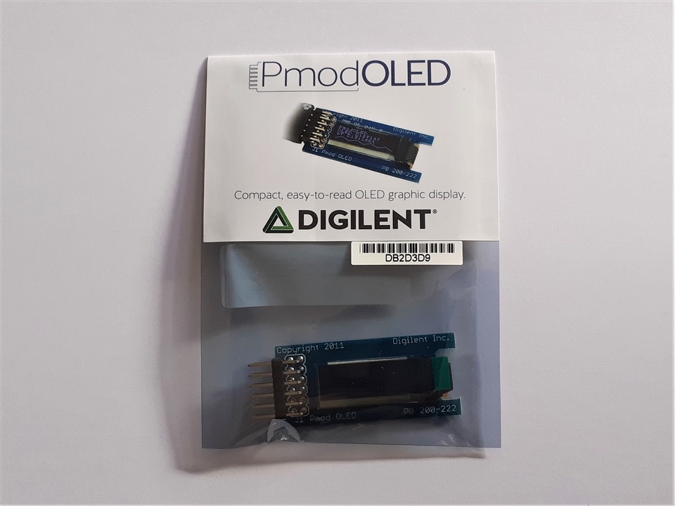
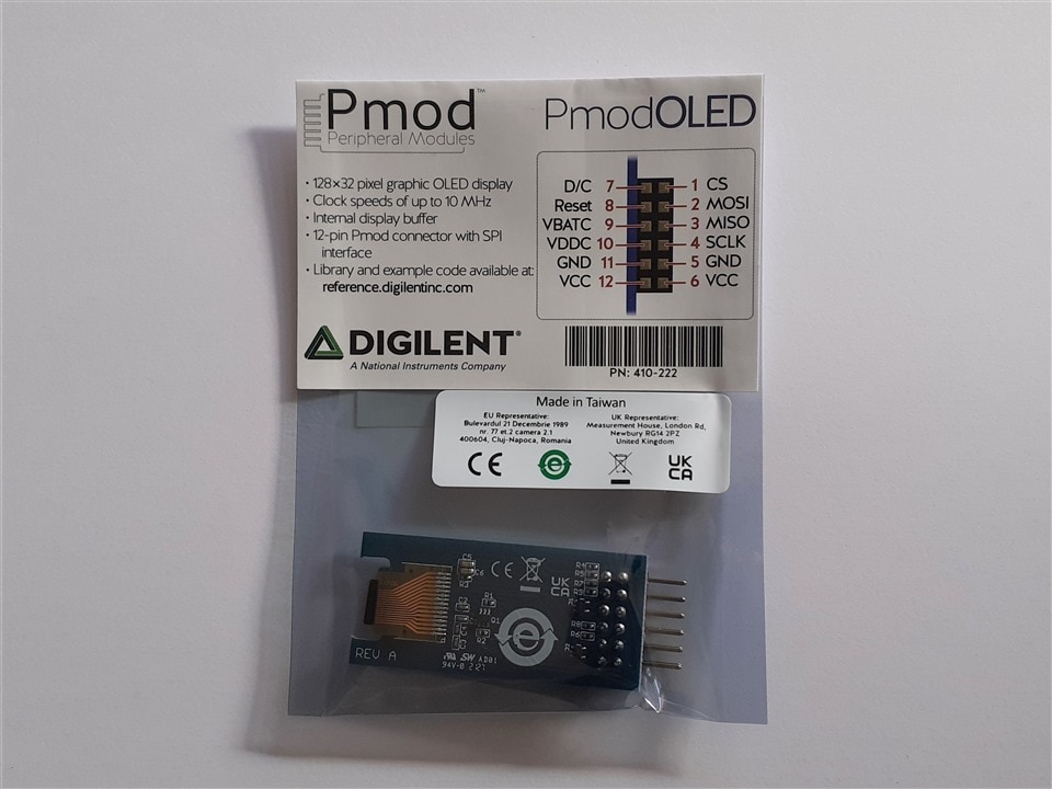
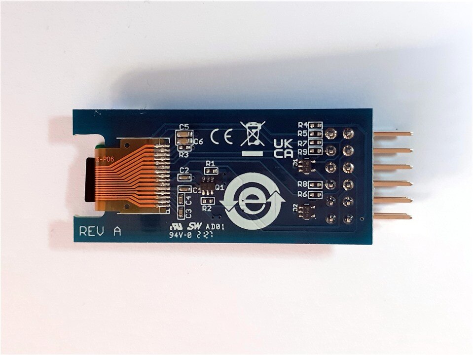
Digilent PmodOLED
The Digilent Pmod OLED (Revision A) is an organic LED module with a 128×32 pixel display. Primary IC SSD1306
References:
| {gallery}Digilent PmodOLED |
|---|
|
Digilent PmodOLED unboxing |
|
Digilent PmodOLED unboxing |
|
Digilent PmodOLED Front |
|
Digilent PmodOLED Back |

Build the Hardware Platform
To create this simple environmental monitor the first thing we need to do is to create a hardware platform using Xilinx Vivado.
We create the hardware platform without writing a single line in RTL. We will only use the block designer aided by the automatisms of the Vivado IP integrator.
For the realization of this guide and this small project I have based myself on the following workshop given by Jayson Bethurem, Product Line Manager: Spartan, Artix, Zynq-7000, Zynq UltraScale+ at Xilinx
- Arty-S7 Workshop: Part 2: Building a Custom Microcontroller in Minutes
- Arty-S7 Workshop: Part 3: Rapid Sensor Prototyping with Digilent Peripheral Modules
Prerequisites
During the hardware creation process we are going to need certain files made by Digilent for the Arty S7 50 board and the Pmod modules that we are going to use.
A. Download Master XDC files
We will use the XDC files to constrain ports that have been omitted from the board file.
- Go to GitHub - Digilent/digilent-xdc: A collection of Master XDC files for Digilent FPGA and Zynq boards. and download the Arty-S7-50-Master.xdc
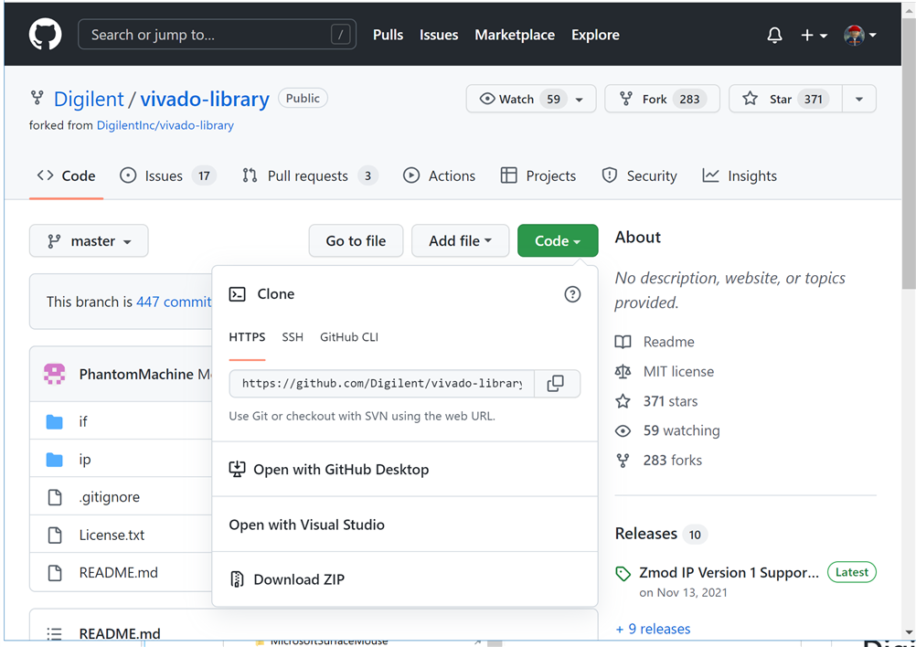
B. Download the Digilent Vivado Library
Digilent provides several IPs that are designed to make implementing and using a Pmod on an FPGA as straightforward as possible.
The Digilinet Vivado Library contains the Pmod IPs and Microblaze Drivers.
- Go to GitHub - Digilent/vivado-library and clone or download the library as zip.
1. Create a New Vivado Project
- Open Vivado 2021.1 and Create a new project for the Arty S7 50 Board. See previous blog: Arty S7 50 First Baremetal Software Project
- At the Select Project Type screen, choose RTL Project and check the Do not specify sources at this time box.
- Select Boards → Filter on Digilentinc, select Arty S7-50
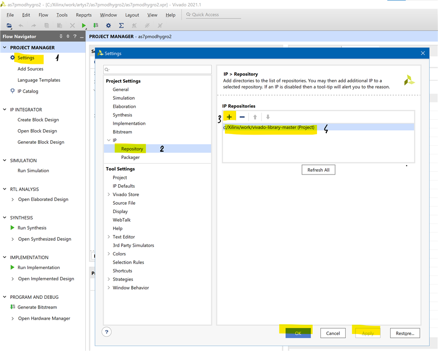
2. Add the Digilent Library Repository, Installing Digilent IP
Once the project has been created, the next step is to map the Digilent Vivado Library as a repository such that we can add the Pmod into the design. This can be done by the project settings tab.
- Go to settings under Project Manager.
- Select IP-> Repository and click the + symbol to add a new repository.
- Select the extracted IP Folder and apply.
2. Create a Vivado IP Integrator Block Design
- Select Create Block Design under IP INTEGRATOR and accept defaults
3. Instantiate a New Microblaze Microcontroller
- First we instantiate a MicroBlaze processor within the Spartan 7 FPGA device.
- Select the + symbol under the BLOCK DESIGN window to add a new IP
- Search for MicroBlaze and double-click it to add it to the block design.
- We need, at minimum, a clock and reset input, as well as local memory from which to execute code. Vivado can automate this, click Run Block Automation.
- MicroBlaze has several preset configurations, select the basic Microcontroller preset.
Block Design now has MicroBlaze Processor with clocking, reset, local memory, debug module, interrupt controller and AXI interconnect block.
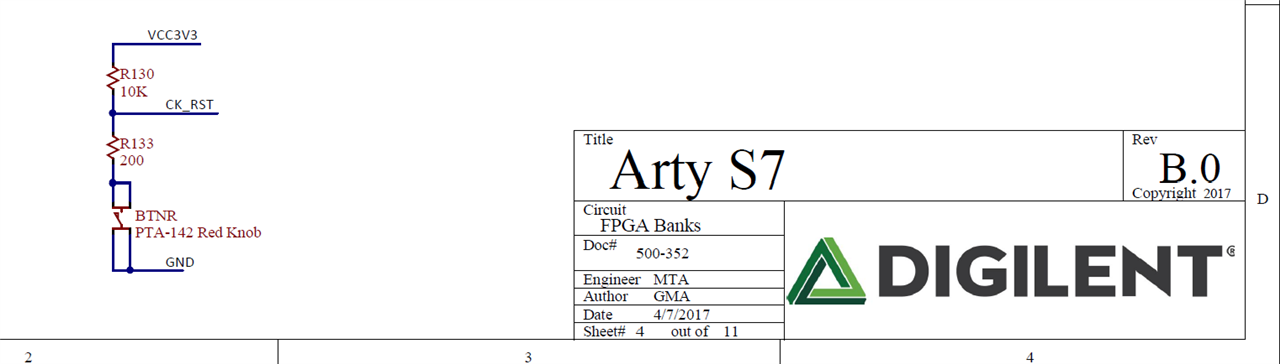
4. Connect Clock and Reset to Board Level Inputs.
The Arty S7-50 board has an active low reset. The red reset button labeled ¨RESET¨generates a high output when at rest and a low output when pressed.
The RESET button is intended to be used in Microblaze designs to reset the processor.
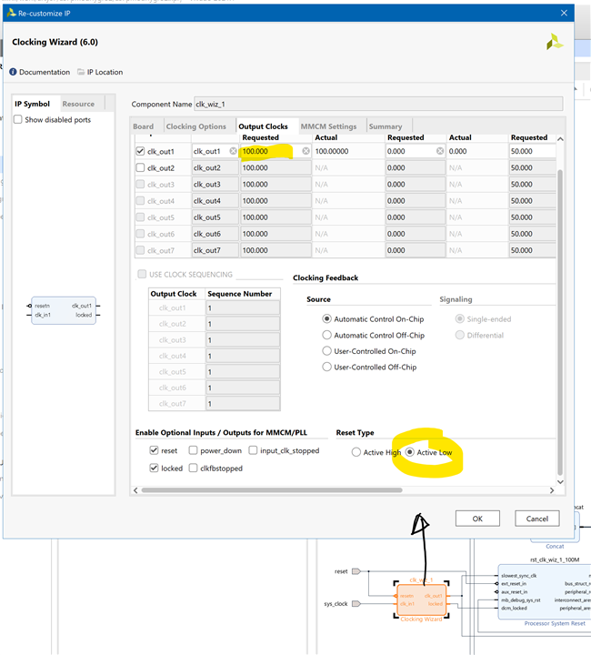
Xilinx offers the Clocking Wizard IP core to help users generate the different clocks required for a specific design. This wizard will properly instantiate the needed MMCMs and PLLs based on the desired frequencies and phase relationships specified by the user. The wizard will then output an easy-to-use wrapper component around these clocking resources that can be inserted into the user’s design. The clocking wizard can be accessed from within the Vivado and IP Integrator tools
The clocking wizard automatically requests an output clock of 100MHz. Internal PLL’s and MMCM’s can synthesize different output clock speeds.
The Arty S7 board includes a 12 MHz crystal oscillator connected to pin F14 (an MRCC input on bank 15) and a 100 MHz crystal oscillator connected to pin R2 (an MRCC input on bank 34). The 12 MHz clock is intended to be used as a general-purpose system clock. The clock can drive MMCMs to generate clocks of various frequencies and with known phase relationships that may be needed throughout a design. The 12 MHz input clock cannot directly drive a PLL because they have a minimum input frequency of 19 MHz.
The 100 MHz clock is intended to drive the system clock input of the Memory Interface Generator (MIG) IP Core to allow for proper use of the DDR3L memory.
- Configure the Clocking Wizard by double-clicking on the IP Block.
- Change the Reset Type to Active Low under Output Clocks.
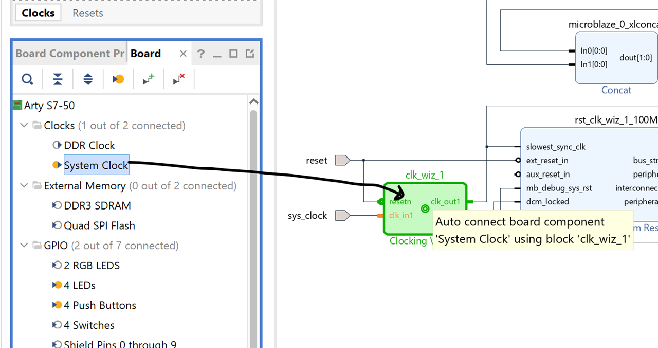
5. Connecting Clock to Board Level Inputs
- Select the Board Tab
- Drag System Clock to Clocking Wizard IP block
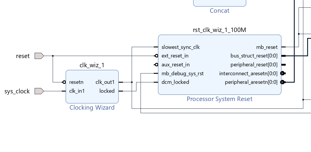
6. Connect Board Resets with the Designer Assistance
- Select the Run Connection Automation, click OK when Auto Connect is done.
- Designer assistance recognizes Reset signals have not been connected.
- Check All Automation checkbox, click OK
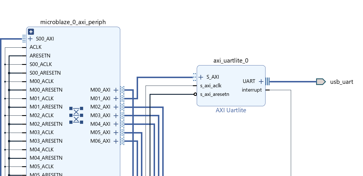
7. Add External Processor Communication, AXI Uartlite
In order to communicate between our on-board processor and our PC, we need to add a USB-UART to the design. The Arty S7 includes an FTDI FT2232HQ USB-UART bridge (attached to connector J10) that allows you to use PC applications to communicate with the board using standard Windows COM port commands. This will allow the processor's STDIO port to communicate to your PC. Serial port data is exchanged with the FPGA using a two-wire serial port (TXD/RXD). I/O commands can be used from the PC directed to the COM port to produce serial data traffic on the V12 and R12 FPGA pins.
- Click Add IP Icon, search for uart and double-click AXI Uartlite.
- With the AXI_Uartlite IP block added, Run Connection Automation by clicking the hyperlink at the top of the screen.
- In Run Connection Automation window, click top checkbox to select all nets and then click OK.
- Verify AXI_Uartlite IP block is fully connected. It has a AXI connection to the AXI Interconnect block and well as AXI clock and reset. Additionally, it auto connected to the board’s USB UART interface.
8. Add Board LEDs and Push Buttons
The Arty S7 board includes two tri-color LEDs, 4 switches, 4 push buttons, 4 individual LEDs, and a reset button.
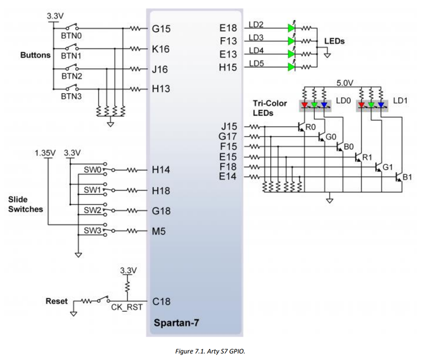
The push buttons and slide switches are connected to the FPGA via series resistors to prevent damage from inadvertent short circuits (a short circuit could occur if an FPGA pin assigned to a push button or slide switch was inadvertently defined as an output). The four push buttons are “momentary” switches that normally generate a low output when they are at rest, and a high output only when they are pressed
The four-individual high-efficiency LEDs are anode-connected to the FPGA via 330-ohm resistors, so they will turn on when a logic high voltage is applied to their respective I/O pin. Additional LEDs that are not user-accessible indicate power-on, FPGA programming status, and USB and Ethernet port status.
To connect the LEDs and Push Buttons in your hardware design:
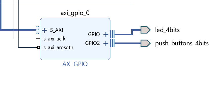
- Simply drag and drop the LED’s and Push Buttons to the IP canvas.
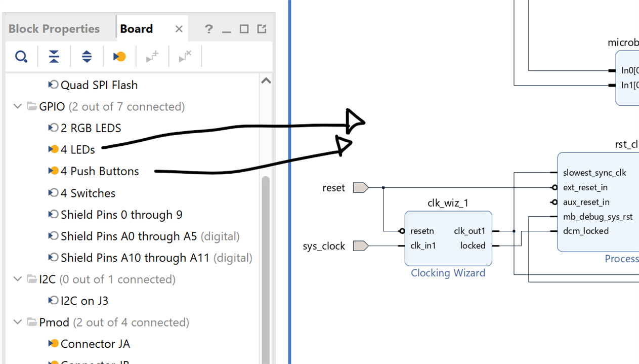
- Run Connection Automation (RCA) again to auto connect new peripherals to the processor. When Run Connection Automation window opens, click OK.
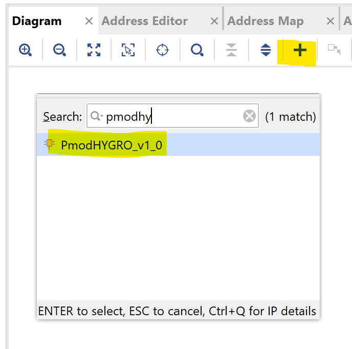
9. Adding a PmodHYGRO Module to the Vivado Project
- Click on the + icon to add IP
- Search for PmodHYGRO_v1_0 and double click it to add it to the design.
- If you can't find it, you have skipped the step of adding the Digilent library repository for Vivado. See step 2.
Drag and drop the Pmod Connector JA component from the Board tab to the design.
Click Run Connection Automation, Select All Automation then click OK.
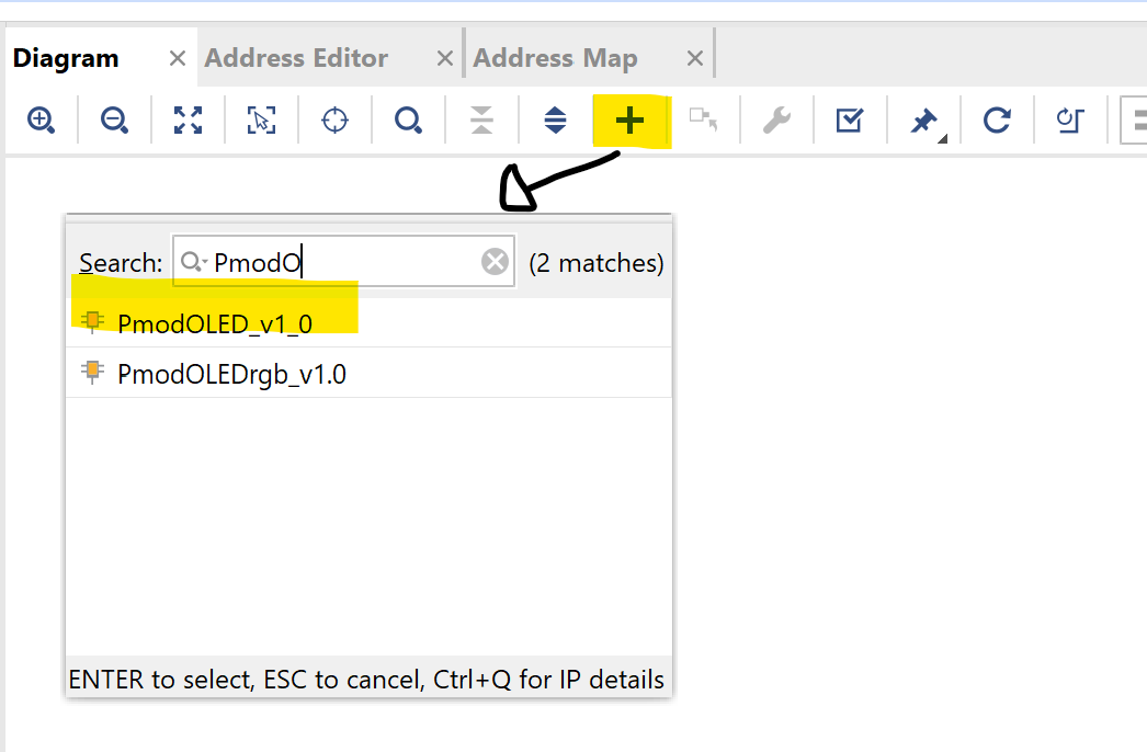
10. Adding a PmodOLED Module to the Vivado Project
- Click on the + icon to add IP
- Search for PmodOLED_v1_0 and double click it to add it to the design.
- If you can't find it, you have skipped the step of adding the Digilent library repository for Vivado. See step 2.
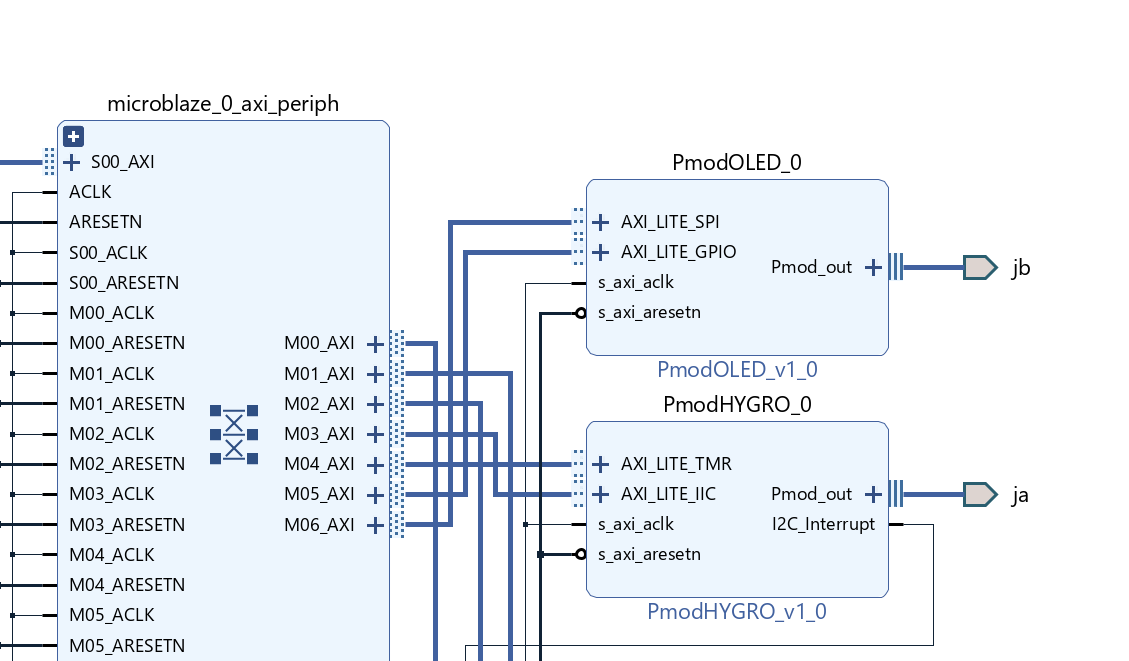
- Drag and drop the Pmod Connector JB component from the Board tab to the design.
- Click Run Connection Automation, Select All Automation then click OK.
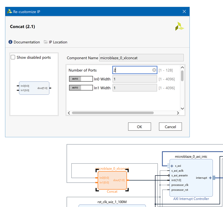
11. Connect all Interrupts
- Locate Concat IP and double-click to customize, connect two interrupt outputs from PmodHYGRO_0 and interrupt from AXI_Uartlite to Concat inputs. Connect Interrupt output of AXI Interrupt Controller to Interrupt input of MicroBlaze.
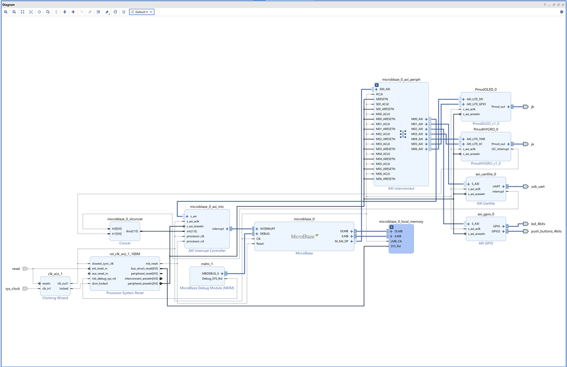
12. Validate the Block Design
- Validate the Block Design

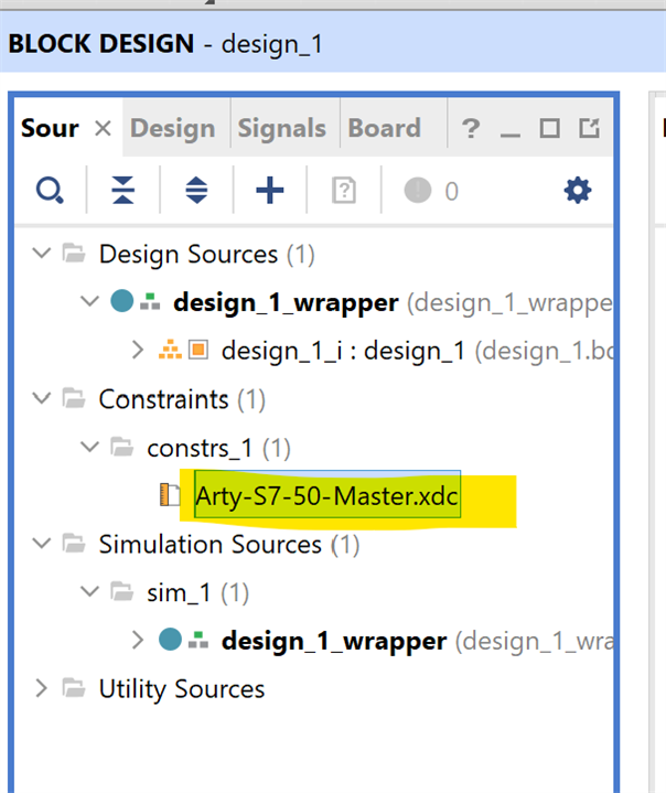
13. Add Constrains for PmodHYGRO
The IP block we are using for the PmodHYGRO module is for an older version of VIVADO and leaves several Pmod JA ports that we have assigned undefined.
- Add a contrains file using the XMC that we have downloaded.
## Pmod Header JA
set_property -dict { PACKAGE_PIN L17   IOSTANDARD LVCMOS33 } [get_ports { ja_pin1_io }]; #IO_L4P_T0_D04_14 Sch=ja_p[1]
set_property -dict { PACKAGE_PIN L18   IOSTANDARD LVCMOS33 } [get_ports { ja_pin2_io }]; #IO_L4N_T0_D05_14 Sch=ja_n[1]
#set_property -dict { PACKAGE_PIN M14   IOSTANDARD LVCMOS33 } [get_ports { ja[2] }]; #IO_L5P_T0_D06_14 Sch=ja_p[2]
#set_property -dict { PACKAGE_PIN N14   IOSTANDARD LVCMOS33 } [get_ports { ja[3] }]; #IO_L5N_T0_D07_14 Sch=ja_n[2]
set_property -dict { PACKAGE_PIN M16   IOSTANDARD LVCMOS33 } [get_ports { ja_pin7_io }]; #IO_L7P_T1_D09_14 Sch=ja_p[3]
set_property -dict { PACKAGE_PIN M17   IOSTANDARD LVCMOS33 } [get_ports { ja_pin8_io }]; #IO_L7N_T1_D10_14 Sch=ja_n[3]
set_property -dict { PACKAGE_PIN M18   IOSTANDARD LVCMOS33 } [get_ports { ja_pin9_io }]; #IO_L8P_T1_D11_14 Sch=ja_p[4]
set_property -dict { PACKAGE_PIN N18   IOSTANDARD LVCMOS33 } [get_ports { ja_pin10_io }]; #IO_L8N_T1_D12_14 Sch=ja_n[4]
14. Create HDL Wrapper for Block Design
- Under the sources tab, right click design_1 and click Create HDL Wrapper.
- Vivado can automatically manage the HDL wrapper. Keep the default setting and click OK
15. Build the FPGA Bitstream for FPGA Configuration
- Click Generate Bitstream
- Click Yes to run synthesis and implementation before generating the bitstream.
- This will build our custom embedded processor bitstream that will configure the FPGA. This step will take several minutes the first time.
16. Export Hardware Design for Vitis SDK
- Select File → Export → Export Hardware….
- Select Fixed Platform Type setting and Select Include Bitstream
- Write down where you have saved the xsa, we will need it for Vitis.
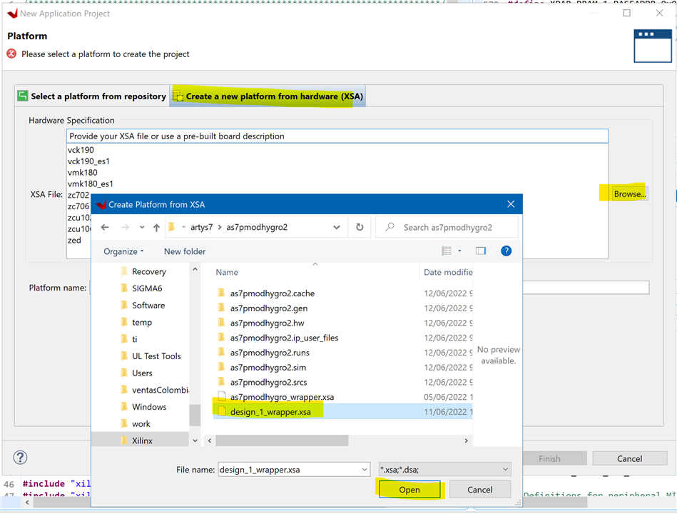
17. Launch Vitis IDE & Create Application Project
- Create Application Project
- Select the Create a new platform from hardware (XSA) tab and browse to find your design_1_wrapper.xsa file.
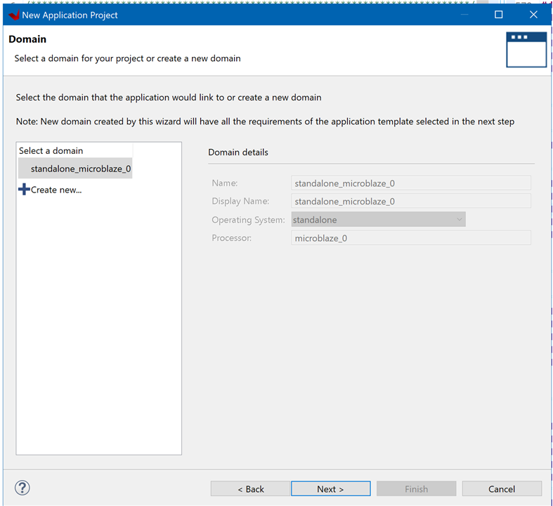
18. Name the Project and Select Domain
- Name the project (no spaces)
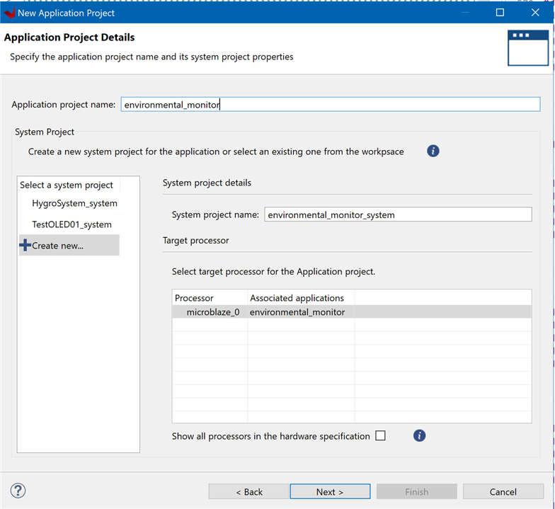
More complex systems can have multiple processor domains, ours only has one. Keep the default settings
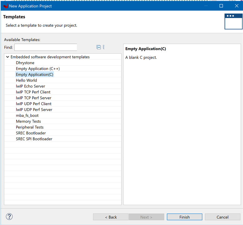
19. Create an Empty Application
- Select Empty Application.
20. Download the Source Code
- Save the following code as main.c
/******************************************************************************/
/*                                                                            */
/* main.c -- Environmental Monitor. Temperature / Humidity                    */
/*  PmodOLED IP + PmodHYGRO                                                   */
/*                                                                            */
/******************************************************************************/
/* Author: Enrique Albertos                                                   */
/* 2022 Public Domain                                                         */
/******************************************************************************/
/* File Description:                                                          */
/*                                                                            */
/* This project initializes and uses the PmodOLED and the PmodHYGRO to        */
/* display temperature and humidity values.                          */
/* Temperature and humidity data are captured from the I2C connection and     */
/* displayed over the serial connection and on the OLED display once per      */
/* second.                                                                    */
/* This application configures UART 16550 to Baud rate 9600. PS7 UART (Zynq)  */
/* is not initialized by this application, since bootrom/bsp configures it to */
/* Baud rate 115200.                                                          */
/*                                                                            */
/*    UART TYPE   BAUD RATE                                                   */
/*    uartns550   9600                                                        */
/*    uartlite    Configurable only in HW design                              */
/*    ps7_uart    115200 (configured by bootrom/bsp)                          */
/*                                                                            */
/******************************************************************************/
/* Revision History:                                                          */
/*                                                                            */
/*    11/06/2022 Enrique Albertos:   Created w/ Vivado 2021.1                 */
/*                                                                            */
/******************************************************************************/
/* Baud Rates:                                                                */
/*                                                                            */
/*    Microblaze: 9600 or what was specified in UARTlite core                 */
/*    Zynq: 115200                                                            */
/*                                                                            */
/******************************************************************************/

/* ------------------------------------------------------------ */
/*                  Include File Definitions                    */
/* ------------------------------------------------------------ */

#include "PmodOLED.h"
#include "PmodHYGRO.h"
#include "sleep.h"
#include "xil_cache.h"
#include "xil_printf.h"
#include "xparameters.h"
#include "xgpio.h"
#include "xil_types.h"

#ifdef __MICROBLAZE__
#define TIMER_FREQ_HZ XPAR_CPU_M_AXI_DP_FREQ_HZ
#else
#define TIMER_FREQ_HZ 100000000
#endif

/* ------------------------------------------------------------ */
/*                  Global Variables                            */
/* ------------------------------------------------------------ */

PmodOLED myOled;
PmodHYGRO myHygro;

/* ------------------------------------------------------------ */
/*                  Forward Declarations                        */
/* ------------------------------------------------------------ */

void DemoInitialize();
void DemoRun();
void DemoCleanup();
void EnableCaches();
void DisableCaches();
void OLED_putFloatVariable(PmodOLED *InstancePtr, int xch, int ych, char * head,
		float value, char * tail);

// To change between PmodOLED and OnBoardOLED is to change Orientation
const u8 orientation = 0x0; // Set up for Normal PmodOLED(false) vs normal
// Onboard OLED(true)
const u8 invert = 0x0; // true = whitebackground/black letters
// false = black background /white letters

#define BTN_MASK 0b1111
#define LED_MASK 0b1111
#define BTN1_MASK 0b0001
#define BTN2_MASK 0b0010
#define BTN3_MASK 0b0100
#define BTN4_MASK 0b1000
#define LED1_MASK 0b0001
#define LED2_MASK 0b0010
#define LED3_MASK 0b0100
#define LED4_MASK 0b1000
#define CELSIUS_LED LED1_MASK
#define FAHRENHEIT_LED LED1_MASK

// Get device IDs from xparameters.h
#define BTN_ID XPAR_AXI_GPIO_0_DEVICE_ID
#define LED_ID XPAR_AXI_GPIO_0_DEVICE_ID
#define BTN_CHANNEL 2
#define LED_CHANNEL 1

XGpio_Config *cfg_ptr;
XGpio led_device, btn_device;


/* ------------------------------------------------------------ */
/*                  Function Definitions                        */
/* ------------------------------------------------------------ */

int main() {
	DemoInitialize();
	DemoRun();
	DemoCleanup();

	return 0;
}

void DemoInitialize() {
	EnableCaches();

	xil_printf("HYGRO Init Started\n\r");
	HYGRO_begin(&myHygro,
	XPAR_PMODHYGRO_0_AXI_LITE_IIC_BASEADDR, 0x40, // Chip address of PmodHYGRO IIC
			XPAR_PMODHYGRO_0_AXI_LITE_TMR_BASEADDR,
			XPAR_PMODHYGRO_0_DEVICE_ID,
			TIMER_FREQ_HZ // Clock frequency of AXI bus, used to convert timer data
			);
	xil_printf("HYGRO Init Done\n\r");

	xil_printf("OLED Init Started\n\r");
	OLED_Begin(&myOled, XPAR_PMODOLED_0_AXI_LITE_GPIO_BASEADDR,
	XPAR_PMODOLED_0_AXI_LITE_SPI_BASEADDR, orientation, invert);
	xil_printf("OLED Init Done\n\r");

	// Initialize LED Device
	cfg_ptr = XGpio_LookupConfig(LED_ID);
	XGpio_CfgInitialize(&led_device, cfg_ptr, cfg_ptr->BaseAddress);

	// Initialize Button Device
	cfg_ptr = XGpio_LookupConfig(BTN_ID);
	XGpio_CfgInitialize(&btn_device, cfg_ptr, cfg_ptr->BaseAddress);

	// Set Button Tristate
	XGpio_SetDataDirection(&btn_device, BTN_CHANNEL, BTN_MASK);

	// Set Led Tristate
	XGpio_SetDataDirection(&led_device, LED_CHANNEL, 0);

}

/* ------------------------------------------------------------ */
/*** DemoRun()
 **
 **   Parameters:
 **      none
 **
 **   Return Value:
 **      none
 **
 **   Errors:
 **      If the demo is shut down without properly exiting, does not reinitialize
 **      properly.
 **
 **   Description:
 **      Displays Temperature each 1 second.
 **      Toggles temp units with button 1 pressed
 **      Exists when button 4 is pressed.
 **      Requires UART connection to terminal program on PC.
 */
void DemoRun() {
	long timeCounterMillis;
	u32 buttonsState;
	int button1State;
	int lastbutton1State;
	float temp_degc, hum_perrh, temp_degf;
	u8 bDegreesCelsius = 1;

	xil_printf("UART, I2C and SPI opened for Environment Monitor\n\r");
	XGpio_DiscreteWrite(&led_device, LED_CHANNEL, LED1_MASK);
	while (1) {
        // read buttons
		buttonsState = XGpio_DiscreteRead(&btn_device, BTN_CHANNEL);

        //if button 4 is pressed exit
        if(buttonsState & BTN4_MASK ) {
        	xil_printf("exiting\r\n");
        	// exit
        	break;
        }

        // check button for toggling temperature units
        button1State = buttonsState & BTN1_MASK;
		//if button 1 low to high edge
		if((button1State != lastbutton1State) && button1State && timeCounterMillis > 100) {
        	xil_printf("toggle units\r\n");
        	// toggle temp units mode
        	bDegreesCelsius = !bDegreesCelsius;
        	// change led indicator
        	if (bDegreesCelsius ) {
        		XGpio_DiscreteWrite(&led_device, LED_CHANNEL, LED1_MASK);
        	} else {
        		XGpio_DiscreteWrite(&led_device, LED_CHANNEL, LED2_MASK);
        	}
        	// force environmental data update
        	timeCounterMillis = 1001;
        }
		lastbutton1State = button1State;

        if( timeCounterMillis > 1000) {
        	timeCounterMillis = 0;
			temp_degc = HYGRO_getTemperature(&myHygro);
			temp_degf = HYGRO_tempC2F(temp_degc);
			hum_perrh = HYGRO_getHumidity(&myHygro);
			xil_printf("Temperature: %d.%02d deg F  Humidity: %d.%02d RH\n\r",
					(int) temp_degf, ((int) (temp_degf * 100)) % 100,
					(int) hum_perrh, ((int) (hum_perrh * 100)) % 100);

			// Turn automatic updating off
			OLED_SetCharUpdate(&myOled, 0);

			if(bDegreesCelsius) {
				// Display Temperature Value in Degrees Celsius
				OLED_putFloatVariable(&myOled, 1, 1, "T: ", temp_degc, " C");
			} else {
				// Display Temperature Value in Degrees Fahrenheit
				OLED_putFloatVariable(&myOled, 1, 1, "T: ", temp_degf, " F");
			}
			// Display Relative Humidity Percentage
			OLED_putFloatVariable(&myOled, 1, 3, "H: ", hum_perrh, " %RH");
			// Update display
			OLED_Update(&myOled);
        }

		usleep(1000);
		timeCounterMillis++;
	}
	xil_printf("Exiting PmodOLED Demo\n\r");
}

/*
 * Displays on the OLED a float variable with a header and a tail
 * ie T: 12.67 C
 * OLED_putFloatVariable(&myOled, 1, 1, "T: ", temp_degc, " C");
 */
void OLED_putFloatVariable(PmodOLED *InstancePtr, int xch, int ych, char * head,
		float value, char * tail) {
	OLED_SetCursor(InstancePtr, xch, ych);
	OLED_PutString(InstancePtr, head);
	OLED_PutChar(InstancePtr, ((int) value / 10) % 10 + 48);
	OLED_PutChar(InstancePtr, ((int) value) % 10 + 48);
	OLED_PutString(InstancePtr, ".");
	OLED_PutChar(InstancePtr, ((int) (value * 10)) % 10 + 48);
	OLED_PutChar(InstancePtr, ((int) (value * 100)) % 10 + 48);
	OLED_PutString(InstancePtr, tail);
}

void DemoCleanup() {
	OLED_End(&myOled);
	DisableCaches();
}

void EnableCaches() {
#ifdef __MICROBLAZE__
#ifdef XPAR_MICROBLAZE_USE_ICACHE
	Xil_ICacheEnable();
#endif
#ifdef XPAR_MICROBLAZE_USE_DCACHE
	Xil_DCacheEnable();
#endif
#endif
}

void DisableCaches() {
#ifdef __MICROBLAZE__
#ifdef XPAR_MICROBLAZE_USE_DCACHE
	Xil_DCacheDisable();
#endif
#ifdef XPAR_MICROBLAZE_USE_ICACHE
	Xil_ICacheDisable();
#endif
#endif
}
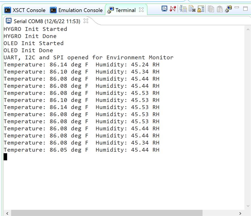
This file contains environmental monitor code
Temperature, and Relative Humidity data is captured over an I2C interface and displayed over UART and over an SPI OLED display
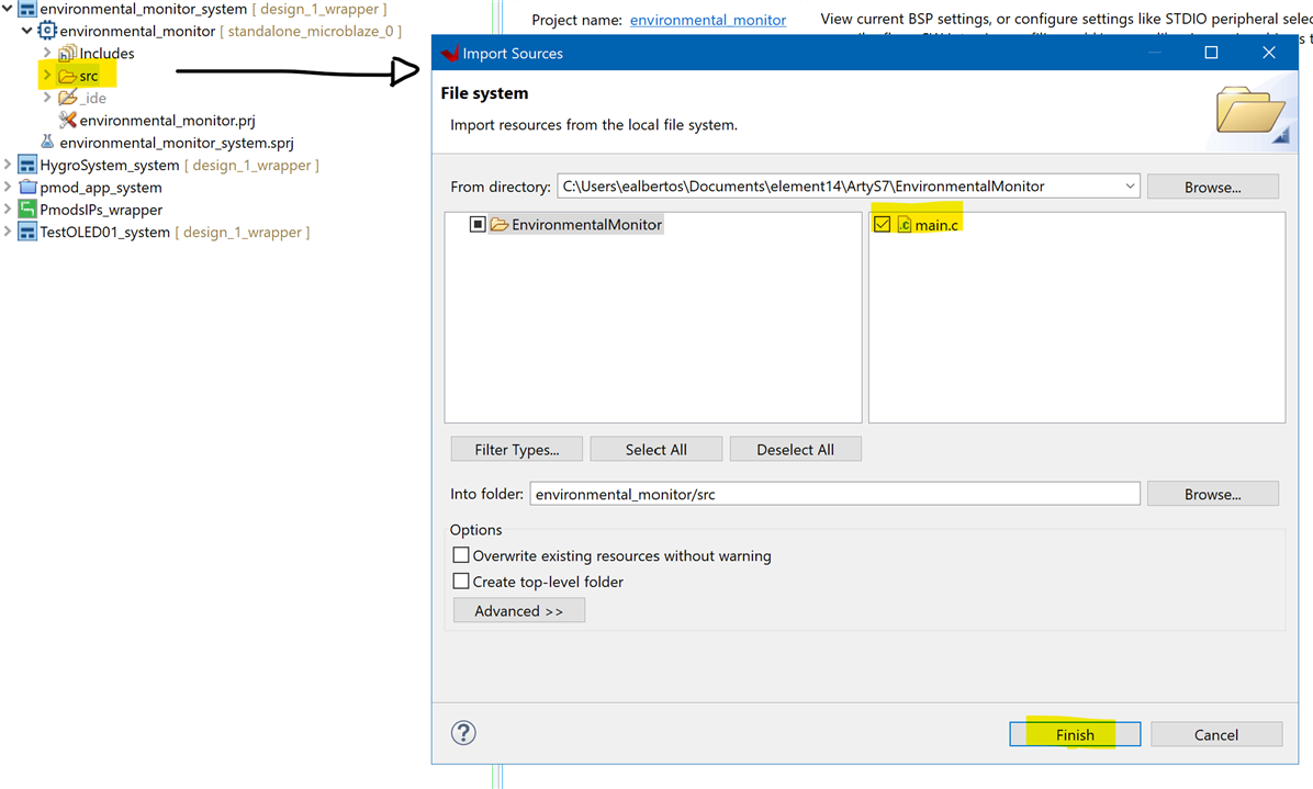
21. Import the Source Code
- Import this main.c file to newly created src directory.
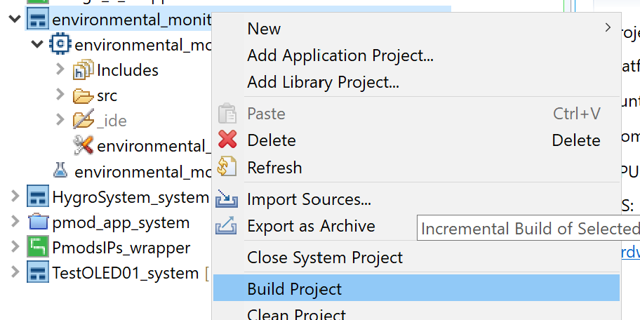
22. Build the Project
- Select environmental_monitor_system then click Build.
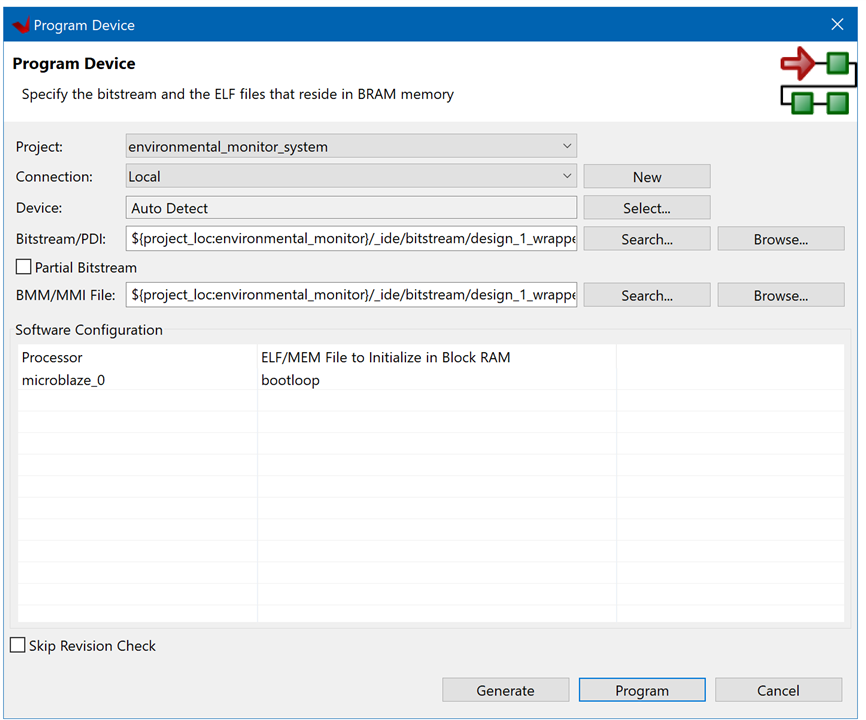
23. Program the Device
- Connect the board to your PC via USB.
- Select Xilinx → Program Device.
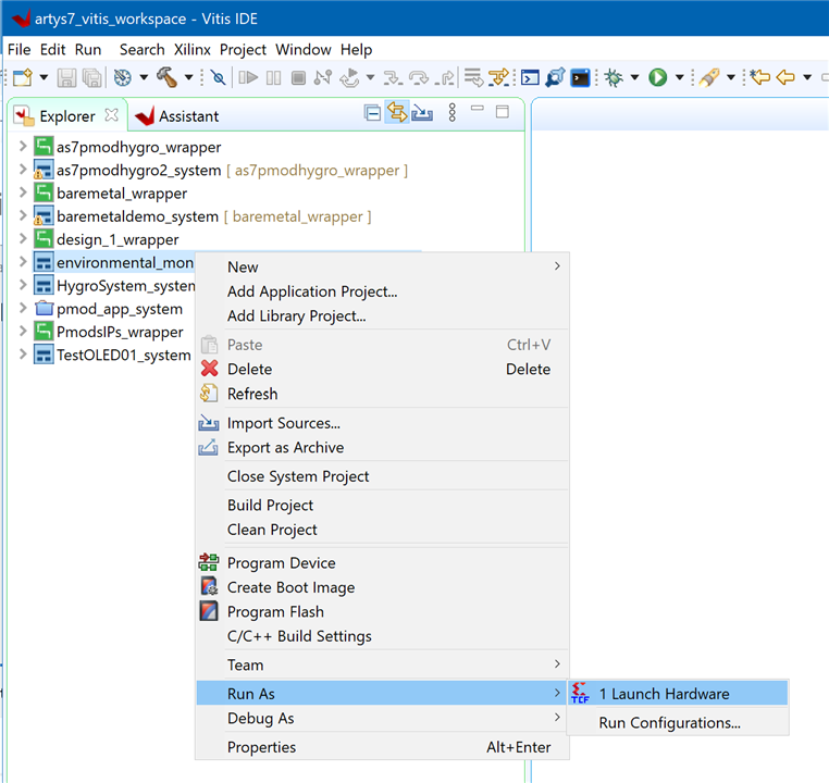
24. Run the Program
- Select environmental_monitor_system then click Run → Run As → Launch Hardware.
25. Visualizing the Serial UART Data Using Vitis
- Launch serial Terminal Window -> Terminal
- Check in the Windows 10 device manager the COM port assigned to your board.
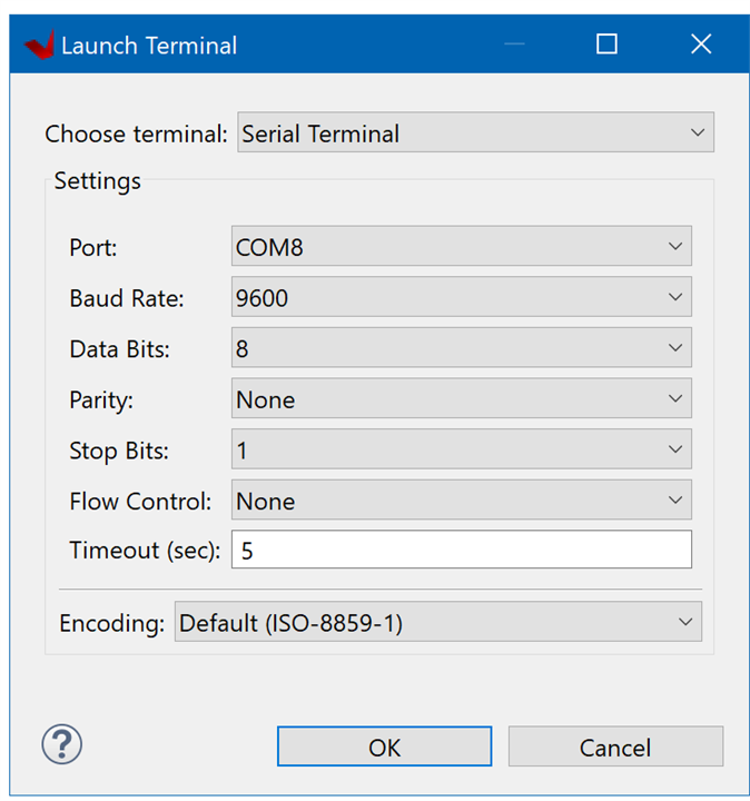
Press OK
Construction
- Connect the PmodHYGRO module to the JA Pmod Header. With the Pin 1 connected. The upper row.
- Connect the PmodOLED module to the JB Pmod Header.
- Power the board.

User Interface
- Use BTN0 to select temperature units. Toggles between Degrees Celsius and Degrees Fahrenheit
- Use BTN3 to end the program.
- LD2 indicates Degrees Celsius Selected
- LD3 indicates Degrees Fahrenheit Selected
- RESET button resets Microblaze softprocessor
The OLED display can show the temperature information in two formats, degrees Celsius or degrees Fahrenheit, selectable by pressing a button.
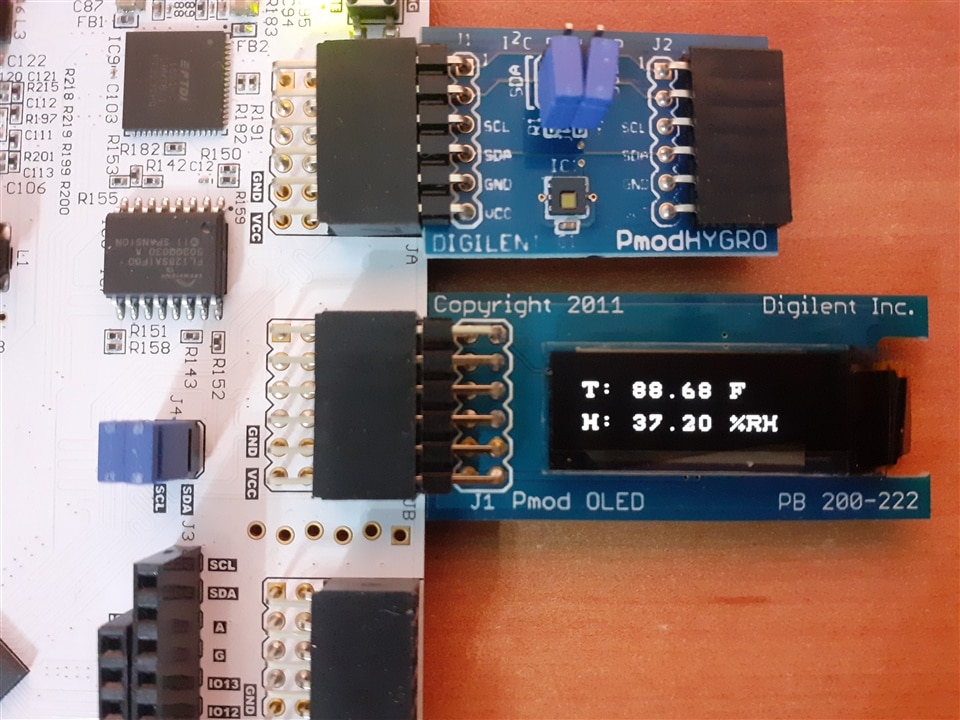
When pressing the first button the monitor toggles temperature units between Celsius and Fahrenheit.

References
- 7 Ways to Leave Your Spartan-6 FPGA - Documents - FPGA - element14 Community
- Arty S7 - Digilent Reference
- Pmod - Digilent Reference
- Pmod HYGRO - Digilent Reference
- Pmod HYGRO Reference Manual - Digilent Reference
- Pmod OLED - Digilent Reference
- Pmod OLED Reference Manual - Digilent Reference
- Arty-S7 Workshop: Part 2: Building a Custom Microcontroller in Minutes
- Arty-S7 Workshop: Part 3: Rapid Sensor Prototyping with Digilent Peripheral Modules
- GitHub - Digilent/digilent-xdc: A collection of Master XDC files for Digilent FPGA and Zynq boards.
- GitHub - Digilent/vivado-library

