


The Avnet Minized board only exposes 4 channels of the integrated analog-to-digital converter (XADC). How can we do to read more analog channels on the Avnet Minized? There is a solution using an external multiplexer and that is what I am going to cover here. In the end we will have a solution that will allow us to read up to 16 analog channels by reading them sequentially two by two.
In this blog I describe how to use the external multiplexer mode of the AMD Zynq-7000 SoC XADC Dual 12 bit 1 MSPS Analog-to-Digital Converter. I make a short introduction to the XADC module, I describe its main modes of operation, I prepare a test bench on a prototyping board and finally I design an addon board for AVNET's Minized development board.
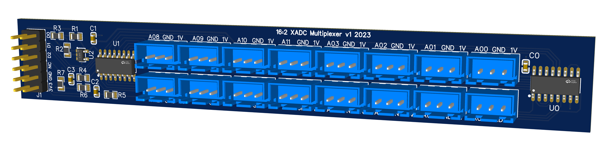
Table of Contents
- The story
- XADC Interfaces on the Zynq-7000 SoC devices
- External Multiplexer Mode
- External Multiplexer Operation
- External multiplexer mode in simultaneous sampling mode
- The XADC in the Avnet Minized
- Hardware design in VIVADO
- Zynq7 Processing System configuration
- Configuring the XADC IP module with the XADC wizard
- Constraints File
- VITIS IDE PS main C code
- Vivado Integrated Logic Analyzer
- Design of an expansion board with up to 16 analog ports for the Minized
- Bill of Materials
- Prototyping on breadboard and test bench
- Conclusion
- References
- Path to Programmable III Training Blog Series
The story
An Analog to Digital Converter (ADC) is a circuit that digitizes a continuous analog signal by converting its voltage level to a discrete digital quantity. The AMD Zynq-700 SoC and the AMD Xilinx FPGA 7 series have an integrated analog-to-digital converter (XADC).
I was recently tinkering with the AMD 7 series FPGA XADC. On that occasion I used it to read the position of 8 analog potentiometers that I wanted to use in the development of a sound music instrument synthesizer based on the Spartan-7 FPGA. You can read the full story on these two following blogs:
- Building FPGA-Based Music Instrument Synthesis: A Simple Test Bench Solution
- SystemVerilog Study Notes. AMD Xilinx 7 series FPGAs XADC

In those two blogs I described how I had used the XADC of the AMD Series 7 FPGAS to read 8 potentiometers that allowed to control the waveforms, pitch, amplitudes and attack and release times in a musical instrument synthesizer. In that design I used the 16-bit synchronous read and write port called the dynamic reconfiguration port (DRP).
I made that design on the development board for the AMD Spartan-7 FPGA Digilent Arty S7. The Digilent Arty S7 exposes 8 ADC channels on the board.
The Digilent Arty S7 exposes 8 ADC channels on the board. However, the Avnet Minized board only exposes 4 ADC channels. Let's see how to expand the number of analog channels up to 16 using an external 16:2 analog multiplexer.
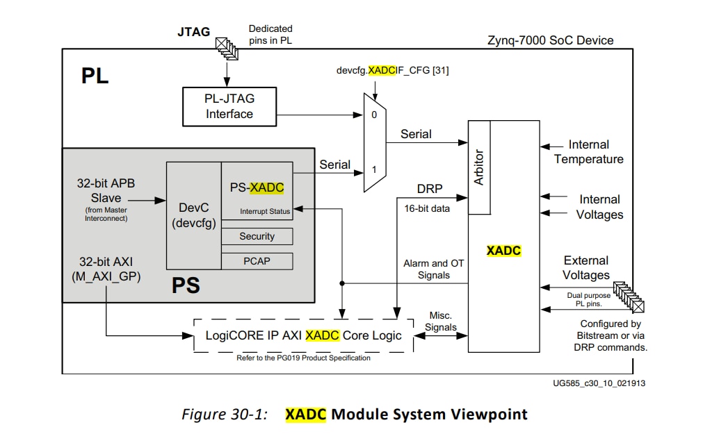
XADC Interfaces on the Zynq-7000 SoC devices
The integrated analog-to-digital converter XADC has JTAG and DRP interfaces for accessing the XADC’s status and control registers in the 7-series FPGAs. Zynq-7000 SoC devices add a third interface, the PS-XADC interface for the PS software to control the XADC.
The XADC has two 12-bit 1 mega samples per second (MSPS) ADCs with separate track and hold amplifiers, an analog multiplexer (up to 17 external analog input channels), and on-chip thermal and on-chip voltage sensors. The two ADCs can be configured to simultaneously sample two external-input analog channels.
Software running in the PS can communicate with the XADC in one of two ways:
- PS-XADC Interface: a 32-bit APB slave interface on the PS interconnect that is FIFO’d and serialized.
- PS to PL AXI master could also be used to control the XADC via the AXI XADC core logic
External Multiplexer Mode
The XADC supports the use an external analog multiplexer to implement several external analog inputs in situations where FPGA I/O resources are limited and auxiliary analog inputs are not available.
The XADC track/hold amplifiers return to track mode as soon as a conversion starts. Therefore, the acquisition on the next channel can start during the current conversion cycle. An output bus called MUXADDR[4:0] allows the XADC to control an external multiplexer.
The address on this bus reflects the channel currently being acquired, and it changes state as soon as the XADC enters acquisition mode. Users can also nominate the channel to be used with an external multiplexer.
External Multiplexer Operation
The next figure illustrates the external multiplexer concept. In this example an external 16:1 analog multiplexer is used instead of consuming the 32 FPGA I/Os required to implement the 16 auxiliary analog input channels using the internal multiplexer.
Any four FPGA I/Os can be used for the external multiplexer decode operation. As shown in the figure, the dedicated analog inputs (VP /VN ) are used to connect the external multiplexer to the XADC block, thereby making 16 analog inputs available.
The external multiplexer mode of operation is enabled by setting the MUX bit in Configuration Register 0 .
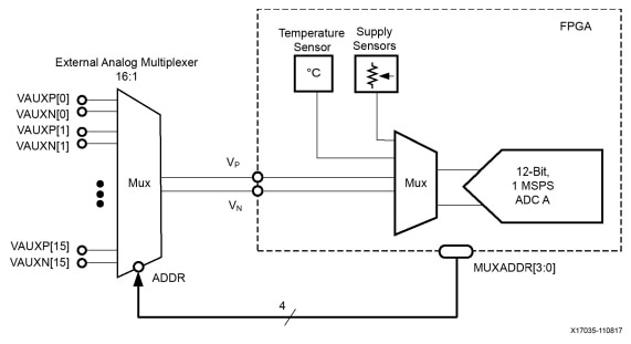
When the MUX bit is set to a 1 , the channel selection bits (CH0 to CH4) in Configuration Register 0 are used to nominate the channel for connection to the external multiplexer.
For example, as shown in the figure, the dedicated analog input channel V P /V N is used. In this case, channel 3 ( 00011b ) should be written to CH4 to CH0 in Control Register 40h .
Any one of the auxiliary channels can also be used for connection to the external multiplexer.
External multiplexer mode in simultaneous sampling mode
In the case of simultaneous sampling mode two channels must be allocated to two external multiplexers to support simultaneous sampling.
The next figure illustrates how the external multiplexer mode is implemented for simultaneous sampling mode. The channels selected for connection are also selected by writing to CH4 to CH0 but are allocated in pairs. For example, writing 16 ( 10000 ) to CH4 to CH0 would select auxiliary channels 0 and 8 for connection to external multiplexers as shown in the figure.
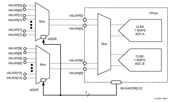
When placed in simultaneous sampling mode, the sequencer automatically sequences through eight pairs of auxiliary analog input channels for simultaneous sampling and conversion as shown in the next table.
|
Sequence Number |
Bit |
ADC Channel |
Description |
|---|---|---|---|
|
1 |
0 |
16, 24 |
Auxiliary channels 0 and 8 |
|
2 |
1 |
17, 25 |
Auxiliary channels 1 and 9 |
|
3 |
2 |
18, 26 |
Auxiliary channels 2 and 10 |
|
4 |
3 |
19, 27 |
Auxiliary channels 3 and 11 |
|
5 |
4 |
20, 28 |
Auxiliary channels 4 and 12 |
|
6 |
5 |
21, 29 |
Auxiliary channels 5 and 13 |
|
7 |
6 |
22, 30 |
Auxiliary channels 6 and 14 |
|
8 |
7 |
23, 31 |
Auxiliary channels 7 and 15 |
|
x |
8 |
x |
Undefined |
|
x |
9 |
x |
Undefined |
|
x |
10 |
x |
Undefined |
|
x |
11 |
x |
Undefined |
|
x |
12 |
x |
Undefined |
|
x |
13 |
x |
Undefined |
|
x |
14 |
x |
Undefined |
|
x |
15 |
x |
Undefined |
This is the mode I have chosen for the design of the multiplexer. We are going to build a 16:2 multiplexer to take advantage of the simultaneous reading performed by the two ADC converters of the XADC module.
The XADC in the Avnet Minized
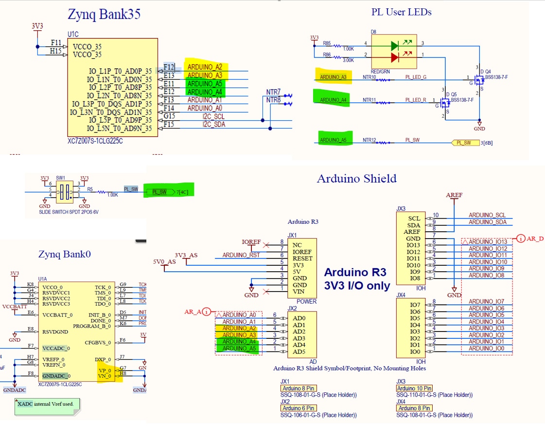
Examining the schematics for the MiniZed , we can see that the Minized has connections for the XADC channels: 0, 8, 1 and 9.
We are going to use channels 0, 8 for the external multiplexer mode in simultaneous sampling mode
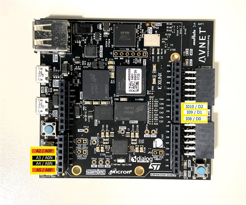
Aux0, Aux8 and Aux1 are connected to the Arduino inputs A0 – A5. These are bipolar inputs with the P and N signals broken out the connector.
We can access the AD0P, AD0N, AD8P and AD8N ports from the headers for the Arduino Shield, the pins ARDUINO_A2, ARDUINO_A3, ARDUINO_A4, ARDUINO_A5
The ARDUINO_A2 pin is only connected to the Zynq Bank 35 but
- ARDUINO_A3 and ARDUINO_A4 are both connected to the gate of two BSS138 N-CHANNEL MOSFET for controlling the bi-element PL-LED.
- The ARDUINO_A5 is connected to the DIP PL switch.
Hardware design in VIVADO
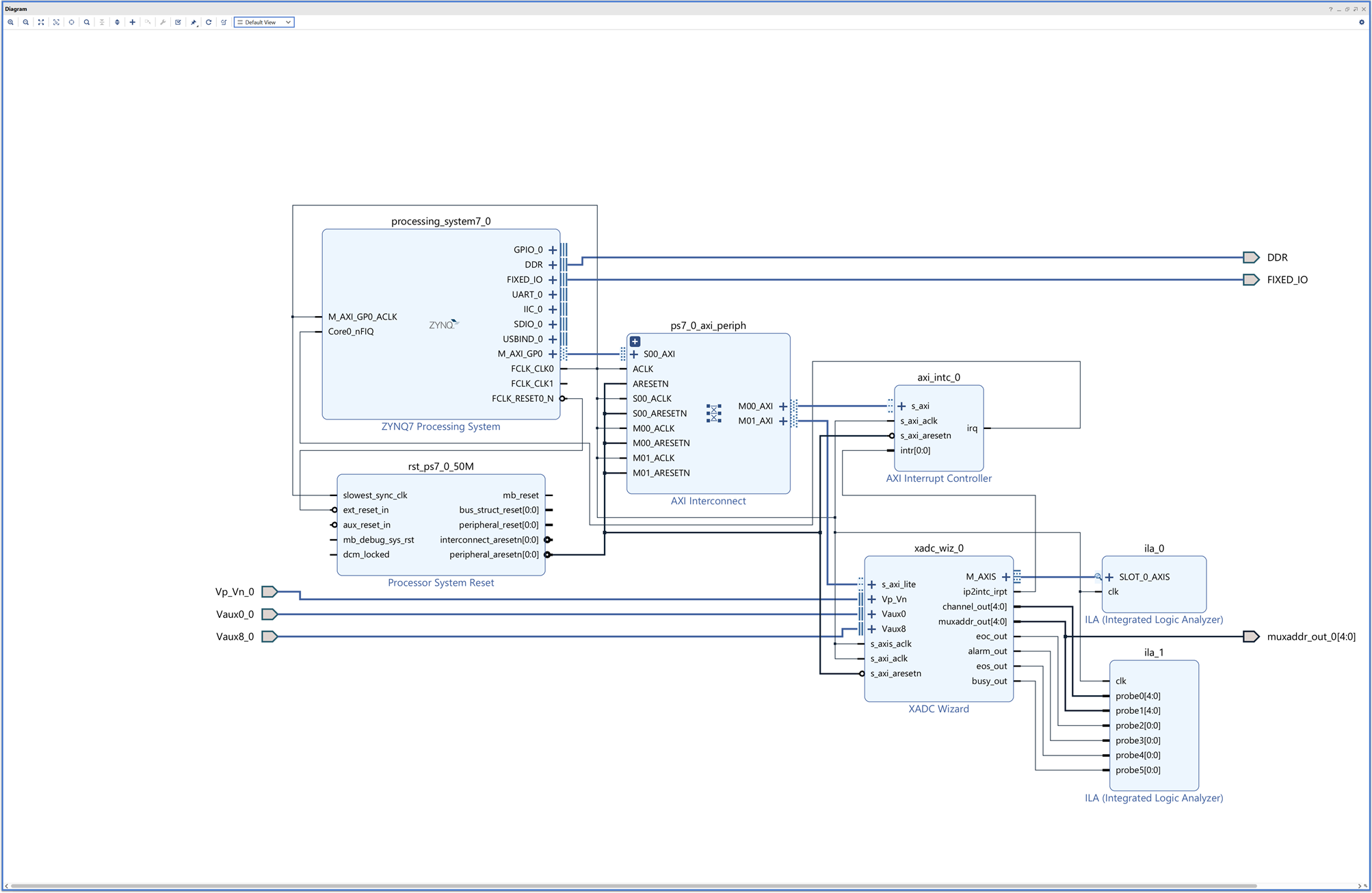
Here is the block diagram we are going to use for testing the XADC External Multiplexer Mode.
Within Vivado, we can then configure the XADC to enable only the desired channels Vauxp0/Vauxn0 and Vauxp8/Vauxn8 in simultaneous selection and with the external multiplexer enabled.
Note that we have added two IP Integrated Logic Analyzer (ILA) modules on the outputs of the XADC module.
Project settings
Block Design
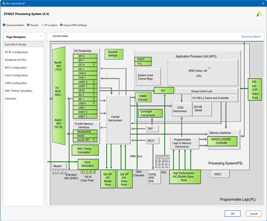
Zynq7 Processing System configuration
- Enable GP Master AXI Interface: M AXI GP0 AXI master interface 0
- Enable fabric interrupts Core0_nFIQ
- Configure PL Fabric Clock FCLK_CLK0 100 MHz
Configuring the XADC IP module with the XADC wizard
We are going to configure the XADC module from the ARM A9 Processor System, select the AXI4Lite Interface option.
- Select continuous mode.
- Select simultaneous selection so we can use both ADC converters
- Enable AXI4Stream. We will use the Integrated Logic Analyzer to view this stream output.
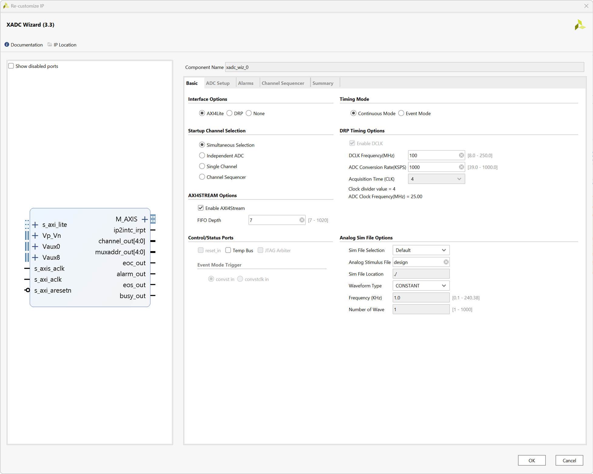
Enable the External Multiplexer and select VAUXP0/VAUXN0 as Channel for MUX
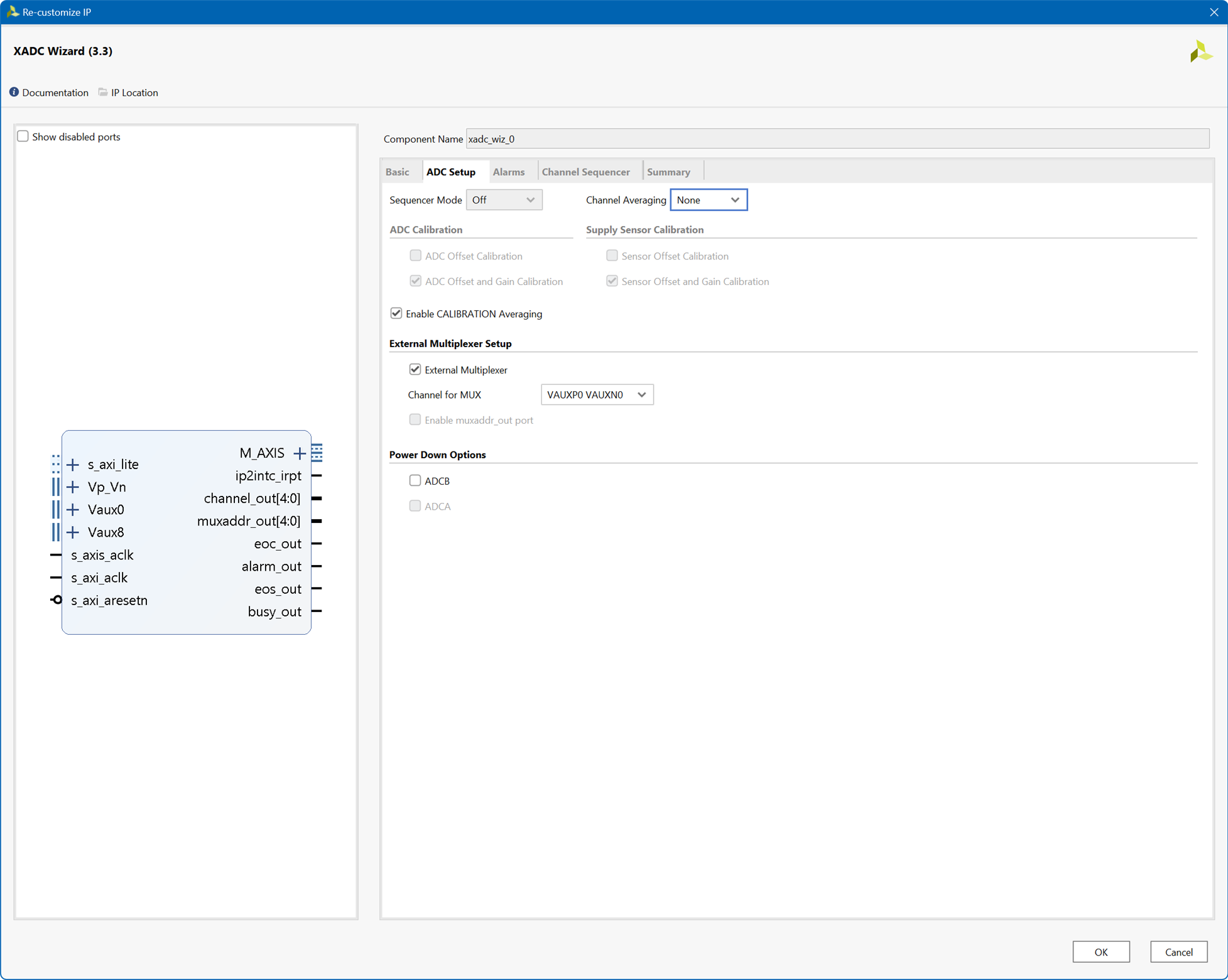
We will configure channel sequence later from the PS
Constraints File
We only need three outputs for the multiplexer output to select addresses from 0 to 7 but we define 5 ports to see how the XADC external multiplexer works.
Later we can ignore the two most significant bits by taking a slice of three ports from the output.
set_property IOSTANDARD LVCMOS33 [get_ports Vaux0_0_v_n]
set_property IOSTANDARD LVCMOS33 [get_ports Vaux0_0_v_p]
set_property IOSTANDARD LVCMOS33 [get_ports Vaux8_0_v_n]
set_property IOSTANDARD LVCMOS33 [get_ports Vaux8_0_v_p]
set_property PACKAGE_PIN E13 [get_ports Vaux0_0_v_n]
set_property IOSTANDARD LVCMOS33 [get_ports {muxaddr_out_0[4]}]
set_property IOSTANDARD LVCMOS33 [get_ports {muxaddr_out_0[3]}]
set_property IOSTANDARD LVCMOS33 [get_ports {muxaddr_out_0[2]}]
set_property IOSTANDARD LVCMOS33 [get_ports {muxaddr_out_0[1]}]
set_property IOSTANDARD LVCMOS33 [get_ports {muxaddr_out_0[0]}]
set_property PACKAGE_PIN R11 [get_ports {muxaddr_out_0[4]}]
set_property PACKAGE_PIN M11 [get_ports {muxaddr_out_0[3]}]
set_property PACKAGE_PIN M10 [get_ports {muxaddr_out_0[2]}]
set_property PACKAGE_PIN N9 [get_ports {muxaddr_out_0[1]}]
set_property PACKAGE_PIN M9 [get_ports {muxaddr_out_0[0]}]
We create the bitstream for the Programmable Logic from Vivado and export the hardware .xsa file along with the bitstream to import from VITIS IDE where we will program the Zynq Processor System.
VITIS IDE PS main C code
From the VITIS IDE we create the hardware platform from de .xsa file, then we create an application project and we program the ARM A9 of the Zynq Processor System with a small program in C. This program
- Initiates the XADC device driver instance
- Runs self-test on the device
- Resets the device
- Sets up the sequencer registers to continuously monitor the auxiliary channel pairs available in XADC
- Sets up the interrupt system
- Enables interrupts
- Sets up the configuration registers to start the sequencer in simultaneous sampling mode
- Reads the ADC channels and outputs data in csv format through the UART
/***************************** Include Files ********************************/

#include "xsysmon.h"
#include "xparameters.h"
#include "xstatus.h"
#include "xintc.h"
#include "stdio.h"
#include "xil_exception.h"
#include "xil_printf.h"
#include "xil_io.h"
#include "sleep.h"

/************************** Constant Definitions ****************************/

/*
 * The following constants map to the XPAR parameters created in the
 * xparameters.h file. They are defined here such that a user can easily
 * change all the needed parameters in one place.
 */
#define SYSMON_DEVICE_ID	XPAR_SYSMON_0_DEVICE_ID
#define INTC_DEVICE_ID		XPAR_INTC_0_DEVICE_ID
#define INTR_ID			XPAR_INTC_0_SYSMON_0_VEC_ID

#define printf xil_printf 	/* Small foot-print printf function */

/**************************** Type Definitions ******************************/

/***************** Macros (Inline Functions) Definitions ********************/

/************************** Function Prototypes *****************************/

static int SysMonIntrExample(XIntc* IntcInstPtr,
			XSysMon* SysMonInstPtr,
			u16 SysMonDeviceId,
			u16 SysMonIntrId);


static void SysMonInterruptHandler(void *CallBackRef);

static int SysMonSetupInterruptSystem(XIntc* IntcInstPtr,
				      XSysMon *SysMonPtr,
				      u16 IntrId );

/************************** Variable Definitions ****************************/

static XSysMon SysMonInst;		/* System Monitor driver instance */
static XIntc IntcInst;			/* Instance of the XIntc driver */

volatile static int EosFlag = FALSE;	/* EOS interrupt */

/****************************************************************************/
/**
*
* Main function that invokes the Interrupt example.
*
* @param	None.
*
* @return
*		- XST_SUCCESS if the example has completed successfully.
*		- XST_FAILURE if the example has failed.
*
* @note		None.
*
*****************************************************************************/
int main(void)
{

	int Status;

	Status = SysMonIntrExample(&IntcInst, &SysMonInst,
				   SYSMON_DEVICE_ID, INTR_ID);
	if (Status != XST_SUCCESS) {
		xil_printf("Extmux Failed\r\n");
		return XST_FAILURE;
	}
	xil_printf("Successfully ran Extmux\r\n");
	return XST_SUCCESS;

}

/****************************************************************************/
/**
*
* This function runs a test on the XADC device using the driver APIs.
*
* The function does the following tasks:
*	- Initiate the XADC device driver instance
*	- Run self-test on the device
*	- Reset the device
*	- Set up sequencer registers to continuously monitor the auxiliary
*	  channel pairs avaibale in XADC
*	- Setup interrupt system
*	- Enable interrupts
*	- Set up configuration registers to start the sequencer in simultaneous
*	  sampling mode
*
* @param	IntcInstPtr is a pointer to the Interrupt Controller
*		driver Instance.
* @param	SysMonInstPtr is a pointer to the XSysMon driver Instance.
* @param	SysMonDeviceId is the XPAR_<SYSMON_ADC_instance>_DEVICE_ID value
*		from xparameters.h.
* @param	SysMonIntrId is
*		XPAR_<INTC_instance>_<SYSMON_ADC_instance>_VEC_ID value from
*		xparameters.h.
*
* @return
*		- XST_SUCCESS if the example has completed successfully.
*		- XST_FAILURE if the example has failed.
*
* @note		This function may never return if no interrupt occurs.
*
****************************************************************************/
static int SysMonIntrExample(XIntc* IntcInstPtr, XSysMon* SysMonInstPtr,
			     u16 SysMonDeviceId, u16 SysMonIntrId)
{
	int Status;
	XSysMon_Config *ConfigPtr;
	u32 IntrStatus;
	u32 IntrEnable;
	u32 AdcData[16];
	int Index;

	printf("\r\nXADC External MUX Example. \r\n");

	/*
	 * Initialize the SysMon driver.
	 */
	ConfigPtr = XSysMon_LookupConfig(SysMonDeviceId);
	if (ConfigPtr == NULL) {
		return XST_FAILURE;
	}

	XSysMon_CfgInitialize(SysMonInstPtr, ConfigPtr, ConfigPtr->BaseAddress);

	/*
	 * Self Test the System Monitor/ADC device.
	 */
	Status = XSysMon_SelfTest(SysMonInstPtr);
	if (Status != XST_SUCCESS) {
		return XST_FAILURE;
	}

	/*
	 * Disable the Channel Sequencer before configuring the Sequencer.
	 */
	XSysMon_SetSequencerMode(SysMonInstPtr, XSM_SEQ_MODE_SAFE);

	Status = XSysMon_SetSeqChEnables(SysMonInstPtr,
			XSM_SEQ_CH_AUX00 |
			XSM_SEQ_CH_AUX01 |
			XSM_SEQ_CH_AUX02 |
			XSM_SEQ_CH_AUX03 |
			XSM_SEQ_CH_AUX04 |
			XSM_SEQ_CH_AUX05 |
			XSM_SEQ_CH_AUX06 |
			XSM_SEQ_CH_AUX07 |
			XSM_SEQ_CH_AUX08 |
			XSM_SEQ_CH_AUX09 |
			XSM_SEQ_CH_AUX10 |
			XSM_SEQ_CH_AUX11 |
			XSM_SEQ_CH_AUX12 |
			XSM_SEQ_CH_AUX13 |
			XSM_SEQ_CH_AUX14 |
			XSM_SEQ_CH_AUX15 );

	if (Status != XST_SUCCESS) {
		return XST_FAILURE;
	}

	/*
	 * Set the ADCCLK frequency equal to 1/32 of System clock for the System
	 * Monitor/ADC in the Configuration Register 2.
	 */
	XSysMon_SetAdcClkDivisor(SysMonInstPtr, 32);

	/*
	 * Setup the interrupt system.
	 */
	Status = SysMonSetupInterruptSystem(IntcInstPtr, SysMonInstPtr,
					    SysMonIntrId);
	if (Status != XST_SUCCESS) {
		return XST_FAILURE;
	}

	/*
	 * Enable global interrupt of System Monitor.
	 */
	XSysMon_IntrGlobalEnable(SysMonInstPtr);

	/*
	 * Clear any pending interrupts.
	 */
	IntrStatus = XSysMon_IntrGetStatus(SysMonInstPtr);
	XSysMon_IntrClear(SysMonInstPtr, IntrStatus);

	/*
	 * Enable EOS interrupts.
	 */
	XSysMon_IntrEnable(SysMonInstPtr, XSM_IPIXR_EOS_MASK);
	IntrEnable = XSysMon_IntrGetEnabled(SysMonInstPtr);
	if ((IntrEnable & XSM_IPIXR_EOS_MASK) != XSM_IPIXR_EOS_MASK) {
		return XST_FAILURE;
	}

	/*
	 * Enable external Mux and connect to Aux CH0 and Aux CH8.
	 */
	XSysMon_SetExtenalMux(SysMonInstPtr, 0x10); /* 0b'10000 to CH[4:0] */

	/*
	 * Enable simultaneous sequencer mode.
	 */
	XSysMon_SetSequencerMode(SysMonInstPtr, XSM_SEQ_MODE_SIMUL);

	XSysMon_GetStatus(SysMonInstPtr);	/* Clear the latched status */

	while(1) {

		/*
		 * Read the ADC converted Data from the data registers.
		 */
		/* Read ADC data for channels 0 - 8 */
		for (Index = 0; Index < 8; Index++) {
			AdcData[Index] = XSysMon_GetAdcData(SysMonInstPtr,
					XSM_CH_AUX_MIN + Index);
			//printf("\r\nAdcData[%d] = %d. \r\n", Index, AdcData[Index] );
		}


		/* Read ADC data for channels 8 - 11 */
		for (Index = 0; Index < 8; Index++) {
			AdcData[Index + 8] = XSysMon_GetAdcData(SysMonInstPtr,
					XSM_CH_AUX_MIN + Index + 8);
			//printf("\r\nAdcData[%d] = %d. \r\n", Index+8, AdcData[Index+8] );
			if (Index!=7) {
				printf("%d,", AdcData[Index+8] );
			} else {
				printf("%d\n", AdcData[Index+8] );
			}
		}

		usleep(100000);
	}

	return XST_SUCCESS;
}

/*****************************************************************************/
/**
*
* This function is the Interrupt Service Routine for the XADC device.
* It will be called by the processor when an interrupt is asserted by the
* device.
*
* There are 10 different interrupts supported
*	- Over Temperature
*	- ALARM 0
*	- ALARM 1
*	- ALARM 2
*	- End of Sequence
*	- End of Conversion
*	- JTAG Locked
*	- JATG Modified
*	- Over Temperature deactivate
*	- ALARM 0 deactivate
*
* This function only handles EOS interrupts.
* User of this code may need to modify the code to meet the needs of the
* application.
*
* @param	CallBackRef is the callback reference passed from the Interrupt
*		controller driver, which in our case is a pointer to the
*		driver instance.
*
* @return	None.
*
* @note		This function is called within interrupt context.
*
******************************************************************************/
static void SysMonInterruptHandler(void *CallBackRef)
{
	u32 IntrStatusValue;
	XSysMon *SysMonPtr = (XSysMon *)CallBackRef;

	/*
	 * Get the interrupt status from the device and check the value.
	 */
	IntrStatusValue = XSysMon_IntrGetStatus(SysMonPtr);

	if (IntrStatusValue & XSM_IPIXR_EOS_MASK) {
		/*
		 * Set End of Conversion  interrupt flag so the code
		 * in application context can be aware of this interrupt.
		 */
		EosFlag = TRUE;
		XSysMon_GetStatus(SysMonPtr); /* Clear the latched status */
	}

	/*
	 * Clear all bits in Interrupt Status Register.
	 */
	XSysMon_IntrClear(SysMonPtr, IntrStatusValue);
 }

/****************************************************************************/
/**
*
* This function sets up the interrupt system so interrupts can occur for the
* System Monitor/ADC.  The function is application-specific since the actual
* system may or may not have an interrupt controller. The System Monitor/ADC
* device could be directly connected to a processor without an interrupt
* controller. The user should modify this function to fit the application.
*
* @param	IntcInstPtr is a pointer to the Interrupt Controller driver
*		Instance.
* @param	SysMonPtr is a pointer to the driver instance for the System
* 		Monitor device which is going to be connected to the interrupt
*		controller.
* @param	IntrId is XPAR_<INTC_instance>_<SYSMON_ADC_instance>_VEC_ID
*		value from xparameters.h
*
* @return	XST_SUCCESS if successful, or XST_FAILURE.
*
* @note		None.
*
*
****************************************************************************/
static int SysMonSetupInterruptSystem(XIntc* IntcInstPtr, XSysMon *SysMonPtr,
				      u16 IntrId )
{
	int Status;

	/*
	 * Initialize the interrupt controller driver so that it's ready to use.
	 */
	Status = XIntc_Initialize(IntcInstPtr, INTC_DEVICE_ID);
	if (Status != XST_SUCCESS) {
		return XST_FAILURE;
	}

	/*
	 * Connect the handler that will be called when an interrupt
	 * for the device occurs, the handler defined above performs the
	 * specific interrupt processing for the device.
	 */
	Status = XIntc_Connect(IntcInstPtr,
				IntrId,
				(XInterruptHandler) SysMonInterruptHandler,
				SysMonPtr);
	if (Status != XST_SUCCESS) {
		return XST_FAILURE;
	}

	/*
	 * Start the interrupt controller so interrupts are enabled for all
	 * devices that cause interrupts. Specify real mode so that the System
	 * Monitor/ACD device can cause interrupts through the interrupt
	 * controller.
	 */
	Status = XIntc_Start(IntcInstPtr, XIN_REAL_MODE);
	if (Status != XST_SUCCESS) {
		return XST_FAILURE;
	}

	/*
	 * Enable the interrupt for the System Monitor/ADC device.
	 */
	XIntc_Enable(IntcInstPtr, IntrId);


	/*
	 * Initialize the exception table.
	 */
	Xil_ExceptionInit();

	/*
	 * Register the interrupt controller handler with the exception table.
	 */
	Xil_ExceptionRegisterHandler(XIL_EXCEPTION_ID_INT,
				(Xil_ExceptionHandler) XIntc_InterruptHandler,
				IntcInstPtr);

	/*
	 * Enable non-critical exceptions.
	 */
	Xil_ExceptionEnable();


	return XST_SUCCESS;
}
UART console output
XADC External MUX Example.
7476,0,0,0,0,0,0,0
7541,382,431,412,411,408,448,437
7513,420,493,381,421,417,414,438
7454,499,388,433,448,410,412,437
7537,453,350,482,438,420,421,428
7581,409,402,462,419,384,436,407
7579,439,398,490,408,422,417,448
7556,384,551,376,415,410,438,412
7473,294,454,347,456,424,429,397
7520,388,444,378,396,434,428,398
7472,460,448,400,453,454,453,418
7572,399,508,429,446,458,447,470
7476,492,376,330,388,442,473,420
7520,516,288,520,455,416,424,446
7490,404,447,376,424,444,437,402
7455,410,389,488,418,416,405,422
7530,411,418,428,396,424,437,380
7538,456,378,404,437,413,433,399
Vivado Integrated Logic Analyzer
In the block diagram we have added two IP blocks of integrated logic analyzers. One for logic signals with which we are going to examine the output logic signals of the XADC IP block and another one specialized in AXI Streams to monitor the XADC block stream output.
Here we have programmed a sequence from channel 0 to 15, the mux output address goes from 0 to 7. Note only 3 bits are used for addresses as we are using simultaneous mode with the two ADC converters running simultaneously.
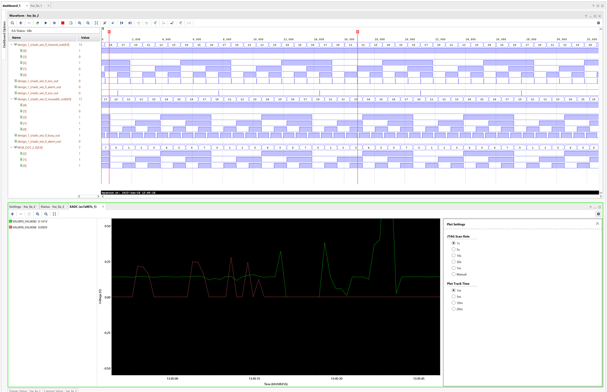
Also we can monitor the output with an external logic analyzer. Here using the AMD Spartan-6 FPGA based Digilent Analog Discovery 2 and the Waveforms software:

Design of an expansion board with up to 16 analog ports for the Minized
DISCLAIMER
I am not an electrical engineer, just a hobbyist, I do not recommend using this circuit without an expert review.
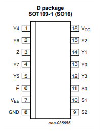
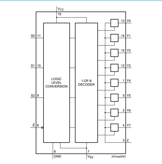
We will use the 74HC4051D,653-Analog Multiplexer / Demultiplexer, 8:1
The 74HC4051 is a single-pole octal-throw analog switch (SP8T) suitable for use in analog or digital 8:1 multiplexer/demultiplexer applications. The switch features three digital select inputs (S0, S1 and S2), eight independent inputs/outputs (Yn), a common input/output (Z) and a digital enable input (E). When E is HIGH, the switches are turned off.
In the case of simultaneous sampling mode two channels must be allocated to two external multiplexers to support simultaneous sampling.
The addresses for the external multiplexer go from 0 to 7, we need three XADC multiplexer output signals to address the 8 analog inputs, D0, d1, D2
We will limit the analog signal to 1V using a buffered voltage divider.

Those headers are for connecting up to 16 10K potentiometers.

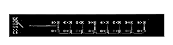
I have designed this double sided PCB with easyEDA. I haven't received the PCBs yet so it's untested. I had never ordered a circuit from an online service before, it will be a new experience for me.
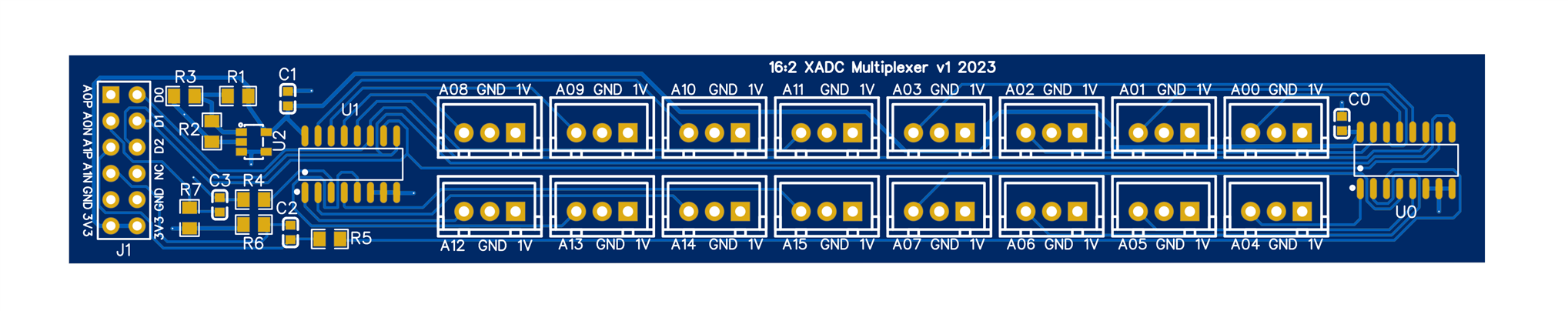
This is how it should look once assembled.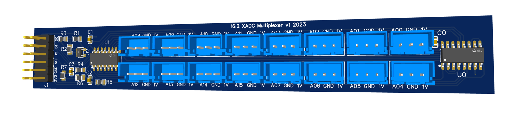
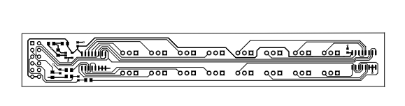
PCB
The project in easyEDA json format:
PCB_PCB_ADCMultiplexerV3_2023-07-02.zip
Gerber_PCB_ADCMultiplexerV3.zip
Bill of Materials
| Product Name | Manufacturer | Quantity | Buy Kit |
|---|---|---|---|
| M20-9740642-Pin Header, Board-to-Board, 2.54 mm, 2 Rows, 12 Contacts, Through Hole Right Angle, M20 | HARWIN | 1 | Buy Now |
| C0603C104K5RACAUTO-SMD Multilayer Ceramic Capacitor, AEC-Q200, 0.1 µF, 50 V, 0603 [1608 Metric], ± 10%, X7R | KEMET | 2 | Buy Now |
| B3B-XH-A (LF)(SN)-Pin Header, Vertical, Wire-to-Board, 2.5 mm, 1 Rows, 3 Contacts, Through Hole Straight, XH | JST (JAPAN SOLDERLESS TERMINALS) | 16 | Buy Now |
| CRCW060322K0FKEA-SMD Chip Resistor, 22 kohm, ± 1%, 100 mW, 0603 [1608 Metric], Thick Film, General Purpose | VISHAY | 1 | Buy Now |
| CRCW080510K0FKEA-SMD Chip Resistor, 10 kohm, ± 1%, 125 mW, 0805 [2012 Metric], Thick Film, General Purpose | VISHAY | 1 | Buy Now |
| CRCW0805220KFKEA-SMD Chip Resistor, 220 kohm, ± 1%, 125 mW, 0805 [2012 Metric], Thick Film, General Purpose | VISHAY | 1 | Buy Now |
| 74HC4051D,653-Analog Multiplexer / Demultiplexer, 8:1, 1 Circuit, 2V to 10V, SOIC-16 | NEXPERIA | 2 | Buy Now |
| LMV321SN3T1G-Operational Amplifier, RR O/P, 1 Amplifier, 1 MHz, 1 V/µs, 2.7V to 5V, TSOP, 5 Pins | ONSEMI | 1 | Buy Now |
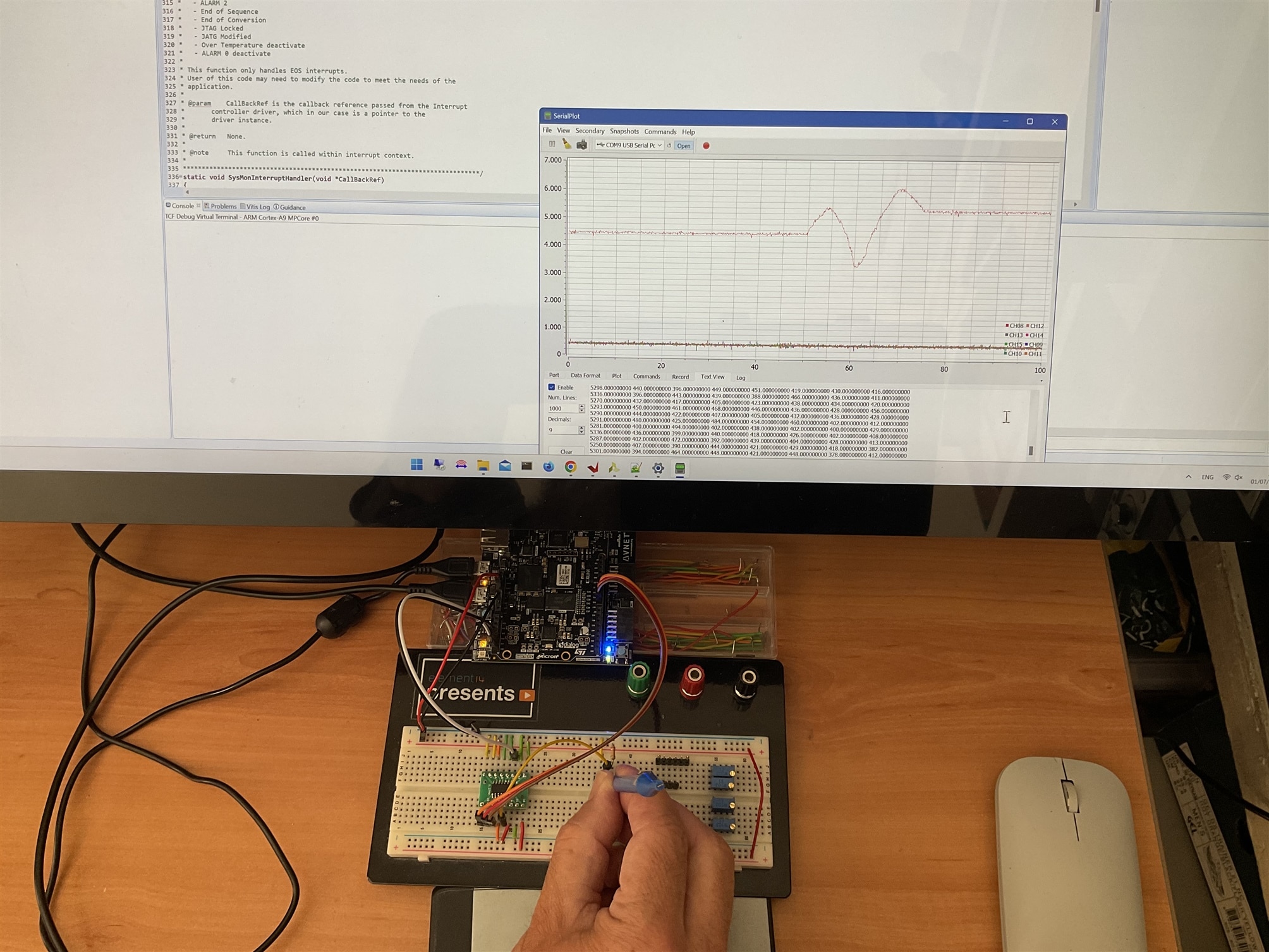
Prototyping on breadboard and test bench
To be able to test the multiplexers on a breadboard I have used a SOP16 adapter board to place a 74HC4051D.
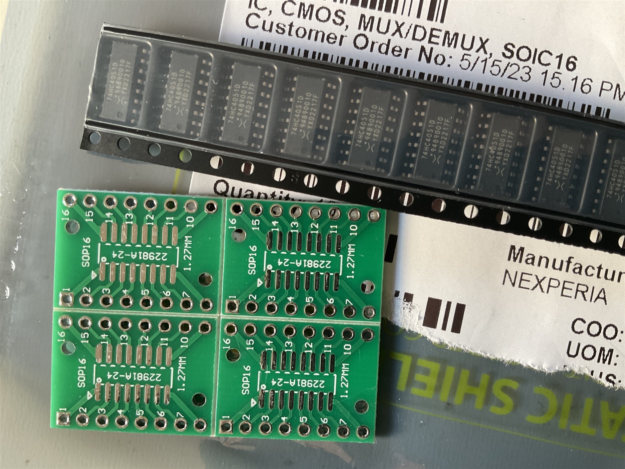
In the image the final result. That size is very easy for soldering.

Then using the multiplexer with all inputs floating except input A0 connected to a potentiometer and an unbuffered voltage divider to limit input signal to 1V0
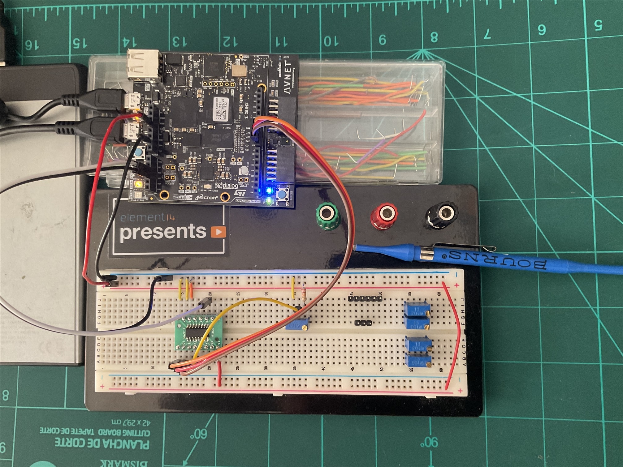
The video shows the ADC readings for the channel 8, which is scanning XADC channels 8 to 15. Analog inputs to GND except A0 connected to the analog 10K potentiometer.
Conclusion
This was going to be a short blog, I had reserved a couple of weeks to do it, but it has been extended for almost five weeks due to my lack of confidence on the matter. Fortunately I have come to understand the module well and best of all, I have managed to test it and verify that it works.
I hope to be able to use all this development for the final project of the course.
References
- https://docs.xilinx.com/r/en-US/ug480_7Series_XADC/External-Multiplexer-Mode
- https://docs.xilinx.com/v/u/en-US/ug585-Zynq-7000-TRM
- xapp554-xadc-layout-guidelines.pdf • Viewer • AMD Adaptive Computing Documentation Portal (xilinx.com)
- xapp795-driving-xadc.pdf • Viewer • AMD Adaptive Computing Documentation Portal (xilinx.com)
-
pg091-xadc-wiz.pdf • Viewer • AMD Adaptive Computing Documentation Portal (xilinx.com)
Path to Programmable III Training Blog Series
- BLOG 1: P2P3 Getting Started. Clockless Hardware Blinky on the Avnet Minized
- BLOG 2: P2P3 AMD Vitis portability and reuse. Migrating a Microblaze bare metal environmental monitor App to the Zynq architecture.
- BLOG 3: P2P3 AMD Zynq-7000 SoC XADC. External Multiplexer Mode.
- BLOG 4: P2P3 AMD Vivado Cascaded Integrator Comb (CIC) Compiler. PDM Microphone to PCM Decimation
- BLOG 5: P2P3 Wireless sensors on the Avnet Minized. Getting Started with PetaLinux
- FINAL PROJECT: AMD Zynq SoC MIDI Vintage Sound Synthesizer - Final
