


Introduction
The Avnet Minized development board has as its sound sensor an ST MP45DT02 MEMS microphone that generates a 1-bit pulse density modulated (PDM) signal. In this blog we are going to see different alternatives to convert that 1-bit PDM signal into an analog signal again or convert it into PCM Pulse Code Modulation format.
Pulse Density Modulation (PDM), it is used in the representation and conversion of analog signals to the digital domain (and vice versa). The amplitude of the signals is represented by the relative density or number of pulses as a function of time. A one-bit stream is unacceptably noisy, but very high sampling rates and noise shaping techniques are used to greatly reduce the noise in the audio spectrum. This noise energy is moved from the audio baseband into the area of the spectrum above 20 kHz, where it is inaudible.
The Pulse Code Modulation (PCM) is a modulation procedure used to transform an analog signal into a sequence of bits (digital signal), it is the standard form of digital audio in computers, compact discs, digital telephony, and other similar applications. In a PCM stream, the amplitude of an analog signal is sampled regularly at uniform intervals, and each sample is quantized to the nearest value within a range of digital steps.
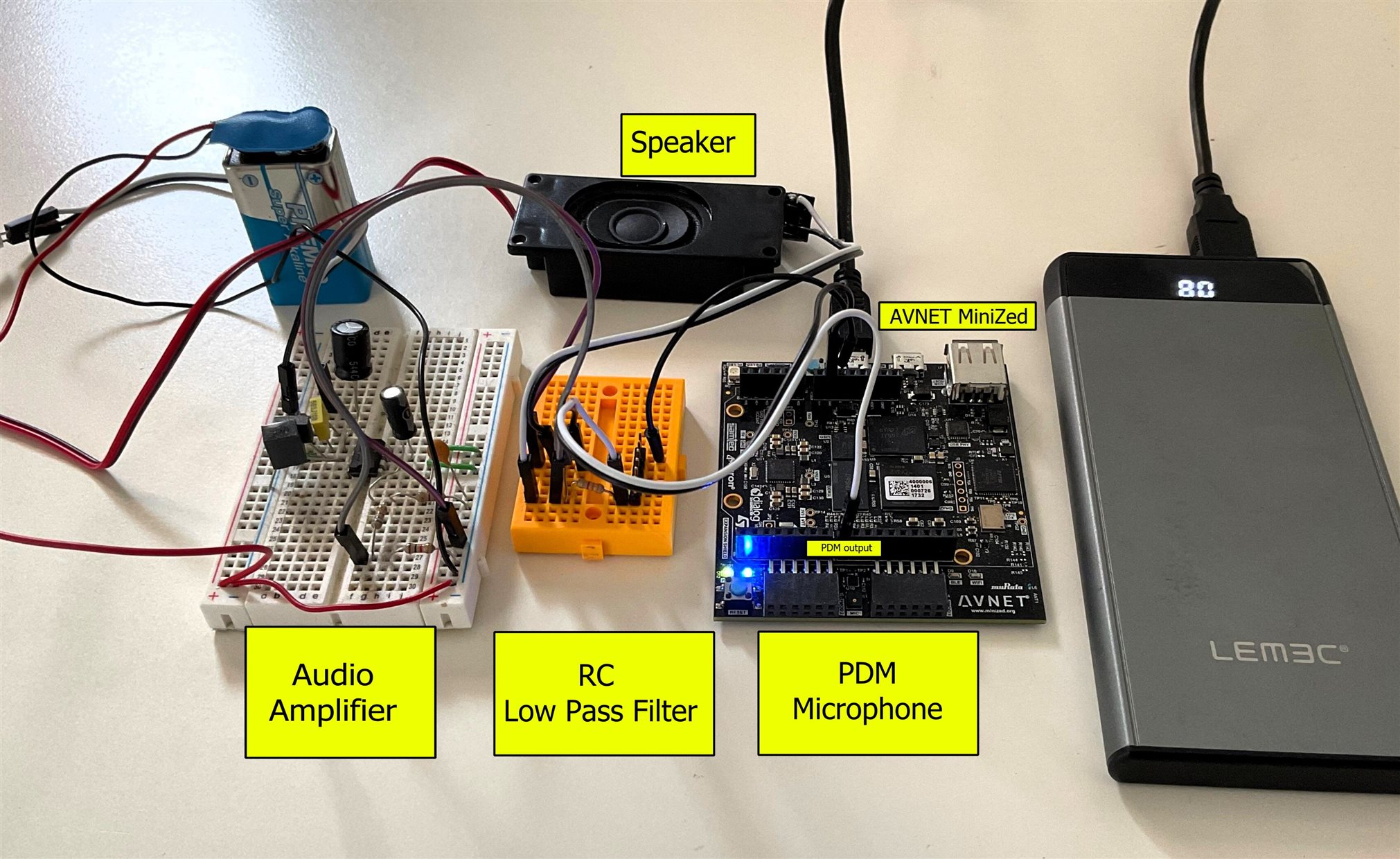
Table of Contents
- Introduction
- Analog to PDM to Analog
- Capturing sound with the MEMS Microphone
- Generating the microphone clock
- Constraints File for the PDM to Analog Conversion
- Vivado Block Diagram
- Vitis Processing System software application
- Hardware Integrated Logic Analyzer Capture
- Low Pass Filter
- The digital to analog converter in action
- Digilent Analog Discovery 2 Oscilloscope
- PDM to PCM decimation
- Cascading Integrating Comb Filter
- Configuration of the AMD LogiCORE IP CIC Compiler
- Conclusion
- References
- Path to Programmable III Training Blog Series
Analog to PDM to Analog
In the first experiment we will activate the MEMS PDM microphone on the MiniZed development board and convert the PDM signal to analog using a simple digital-to-analog converter external to the Minized development board.
Diagram for the first experiment.
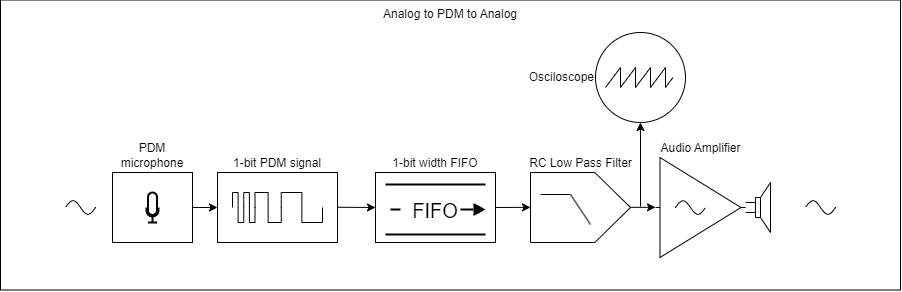
The MEMS microphone on the Minized development board captures sound and generates a 1-bit Pulse Density Modulated (PDM) signal. The signal is passed to a FIFO memory that will produce a small delay, the full flag signal is connected to the ready flag for reading. The output of the FIFO is still a PDM signal that is connected to a very simple DAC consisting of a simple low-pass RC filter.
After going through the DAC we have an analog signal that we will observe with the oscilloscope and amplify it to hear it through a loudspeaker or headphones.
Capturing sound with the MEMS Microphone
The Avnet MiniZed has a built-in audio sensor. It incorporates a Pulse-density modulation (PDM), the MEMS audio sensor omnidirectional digital microphone ST MP34DT05-A.
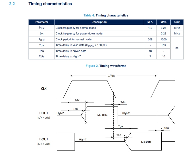
It is hard configured as data valid on clock low.
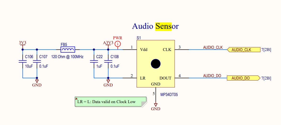
The MP34DT05-A is an ultra-compact, low-power, omnidirectional, digital MEMS microphone built with a capacitive sensing element and an IC interface able to provide a digital signal externally in PDM format.
Datasheet - MP34DT05-A - MEMS audio sensor omnidirectional digital microphone (st.com)
The frequency for normal mode ranges from 1.2 MHz to 3.25 MHz. To activate the microphone we must supply a clock signal in that range. We'll see how to do it later.
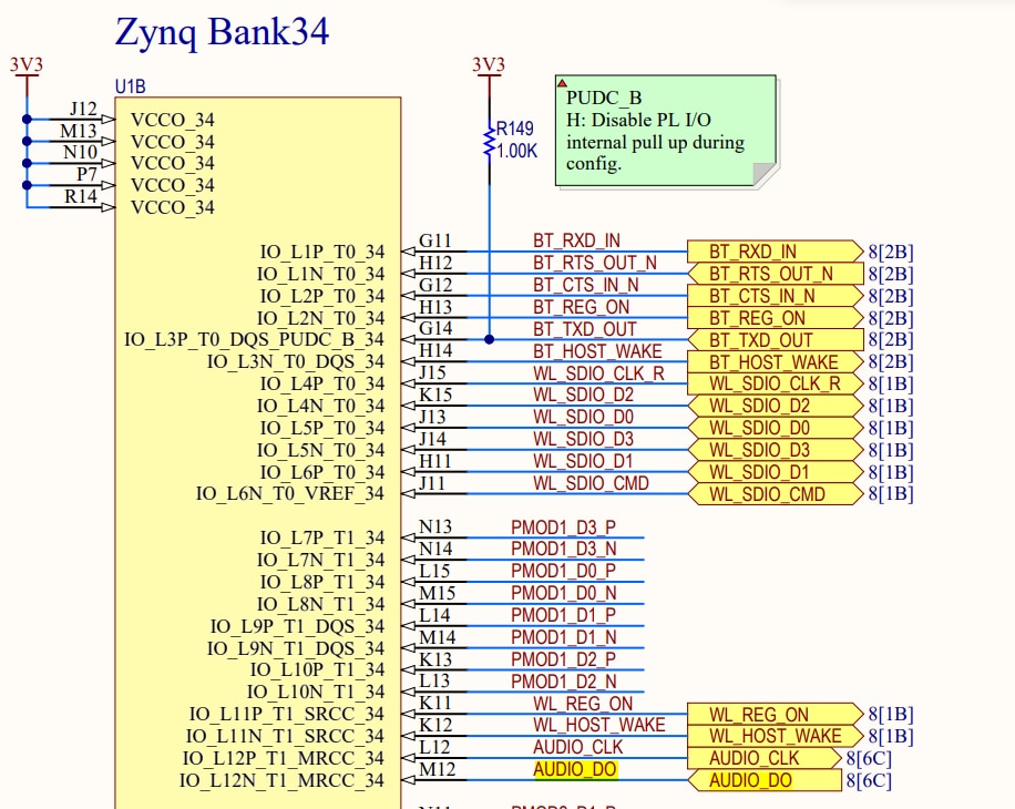
From the Zynq processor on the Minized development board we can only access two of the microphone pins, the pin to supply the clock signal and the pin to receive the 1-bit PDM output signal.
We annotate these Zynq bank 24 pins for our constrains file.
AUDIO_CLK ->IO_L12P_TI_MRCC_34
AUDIO_DO ->IO_L12N_TI_MRCC_34
Generating the microphone clock
We need an slow clock for the MEMS microphone, in the range between 1.2 MHz and 3.25 MHz We cannot generate clocks under 5MHz with the Vivado LogicCore Clock Wizard IP.
We will implement a modulo-M counter with M equals to (input frequency / desired frequency)/2 in order to generate a 2.400 MHz clock signal from a 100 MHz clock signal.
`timescale 1ns / 1ps

module pdm_clk_gen
  #(
    parameter INPUT_FREQ = 100000000,
    parameter OUTPUT_FREQ = 2400000

    )
   (
    input  clk,
    input  rst,
    output mic_clk,
    output clk_rising
    );

   logic   clk_rising_reg;
   logic   mic_clk_reg;

   localparam CLK_DIVIDER = INPUT_FREQ/OUTPUT_FREQ;

   // M-bit counter  M = LOG2(CLK_DIVIDER)
   logic [$clog2(CLK_DIVIDER)-1:0] clk_counter_reg;

   always_ff@(posedge clk) begin
      if (rst) begin
         clk_counter_reg    <= 0;
         mic_clk_reg    <= 0;
         clk_rising_reg <= 0;
      end
      else begin
         clk_rising_reg <= 0;
         if (clk_counter_reg < (CLK_DIVIDER/2)-1) begin
            clk_counter_reg <= clk_counter_reg + 1;
         end
         else begin
            clk_counter_reg    <= 0;
            mic_clk_reg        <= ~mic_clk_reg;
            clk_rising_reg     <= ~mic_clk_reg;

         end
      end
   end

   assign mic_clk = mic_clk_reg; // Microphone clock signal
   assign clk_rising = clk_rising_reg; //  output pulse on the rising edge of the clock for s_axis_data_tvalid


endmodule
Constraints File for the PDM to Analog Conversion
We need to connect the MIcrophone clock as output, the PDM microphone output signal as input and the FIFO delayed pdm output.
#######################################################################
# Microphone
#######################################################################
set_property PACKAGE_PIN L12 [get_ports AUDIO_CLK]
set_property IOSTANDARD LVCMOS33 [get_ports AUDIO_CLK]

set_property PACKAGE_PIN M12 [get_ports AUDIO_DAT]
set_property IOSTANDARD LVCMOS33 [get_ports AUDIO_DAT]

set_property IOSTANDARD LVCMOS33 [get_ports {AUDIO_OUT}]
set_property PACKAGE_PIN M9 [get_ports {AUDIO_OUT}]
Vivado Block Diagram
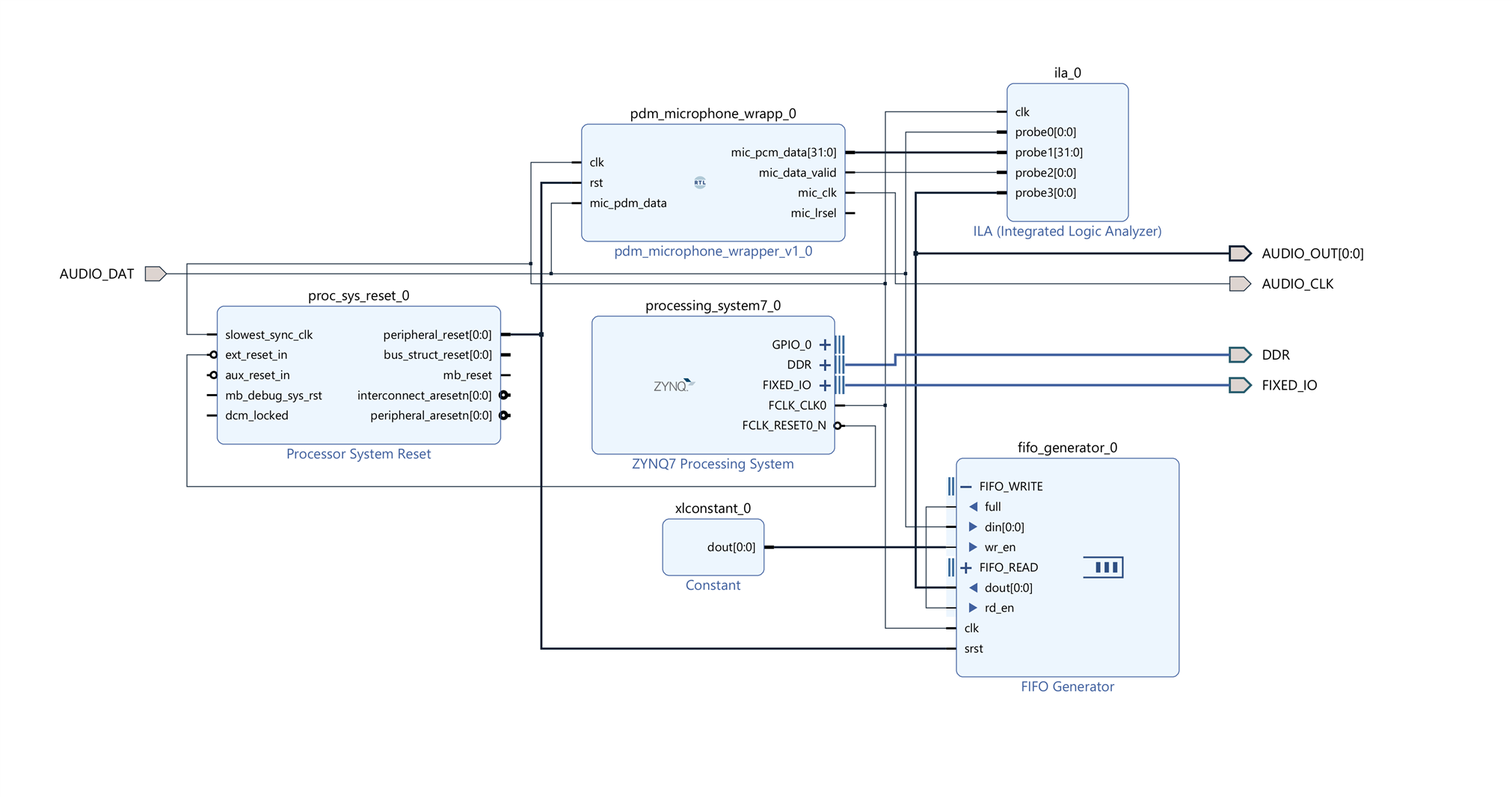
We created a small wrapper for our microphone signal processing module. At the moment we are only going to use the clock signal created with the counter and we are going to connect the output of the microphone to a FIFO memory to produce a small delay between the input signal and the output signal.
Notice that the full FIFO signal from the FIFO generator is connected to the read enabled signal from the FIFO. In this way, until the FIFO is full, data will not start to come out. A little delay.
The PCM signal that also exposes the RTL microphone module will not be dealt with at this time but in the next experiment. At the moment we are only interested in analog to PDM and PDM to analog conversion with a low pass filter as digital to analog converter.
We also added an Integrated Logic Analyzer IP block. The Minized has very few resources so we won't be able to take very large samples but it will help us to debug our system.
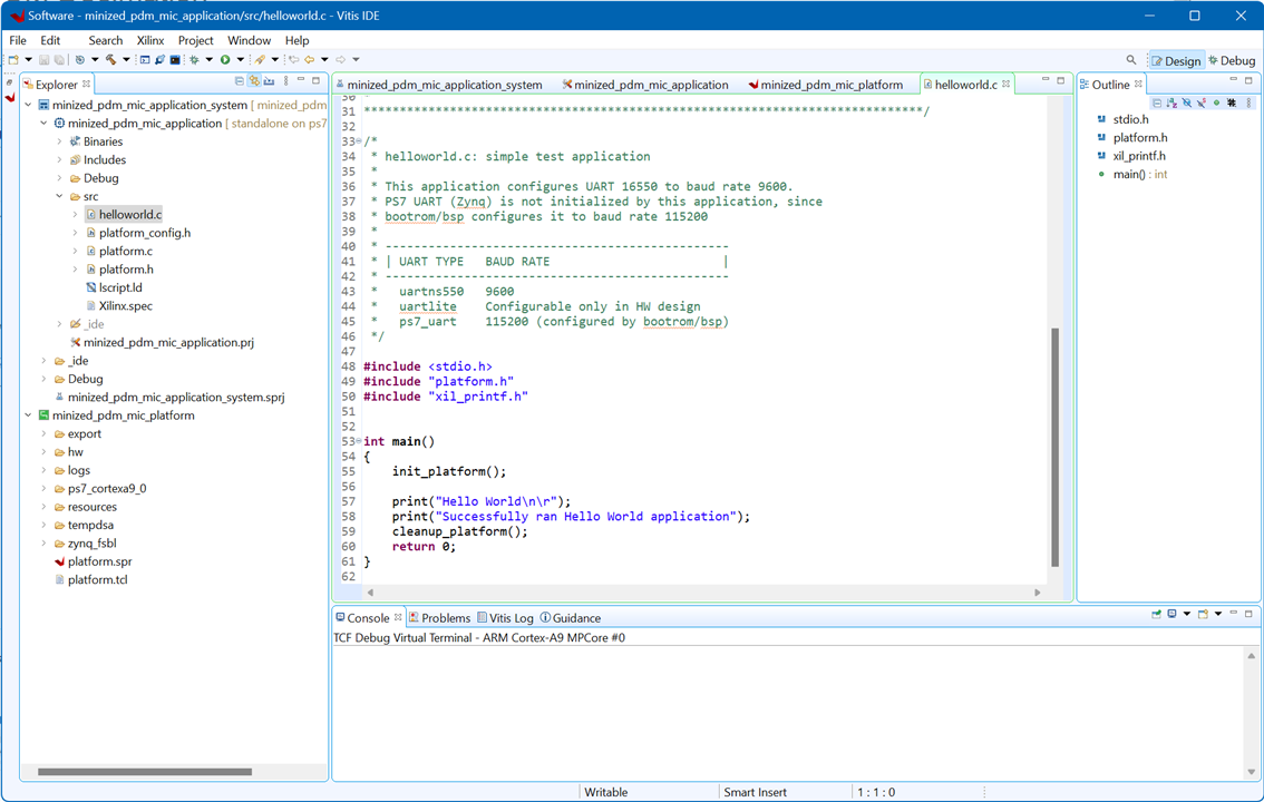
Vitis Processing System software application
The hardware we have designed works autonomously, it only needs the Processing System (PS) for initialization. We can load any application on the PS. For this first experiment we load a simple Hello world! application in the PS.
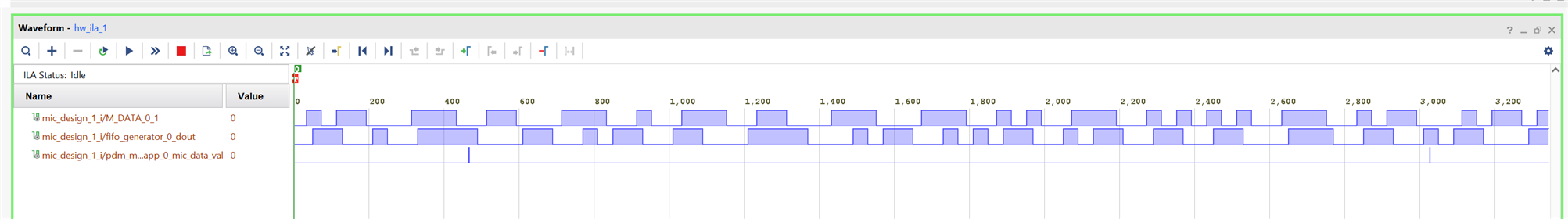
Hardware Integrated Logic Analyzer Capture
In the Zynq hardware integrated logic analyzer image capture we can see the 1-bit PDM output signal of the MEMS microphone and the signal output delayed by the FIFO.
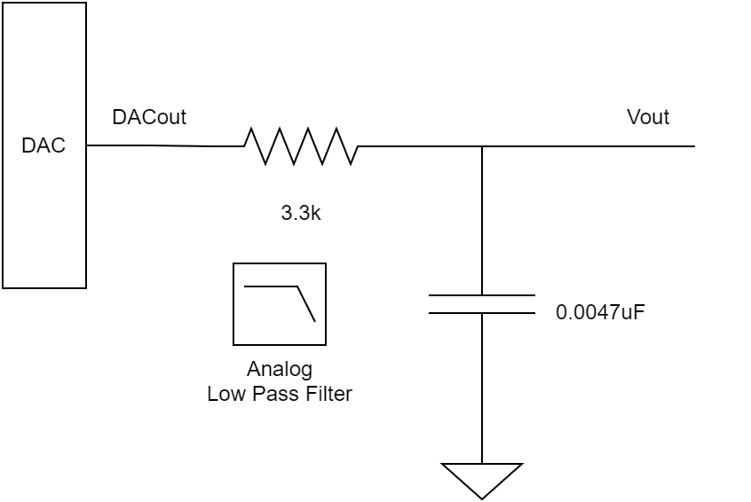
Low Pass Filter
A simple passive RC low-pass filter is used as digital to analog converter.
- Resistance 3.3 kΩ
- Capacitance 0.0047 µF
- -3dB Cutoff Frequency 10 kHz
The digital to analog converter in action
In the image the test bench. As an oscilloscope we use the Digilent Analog Discovery 2 with the Windows software Waveforms.
The oscilloscope is sampling the analog output after the RC lowpass filter.
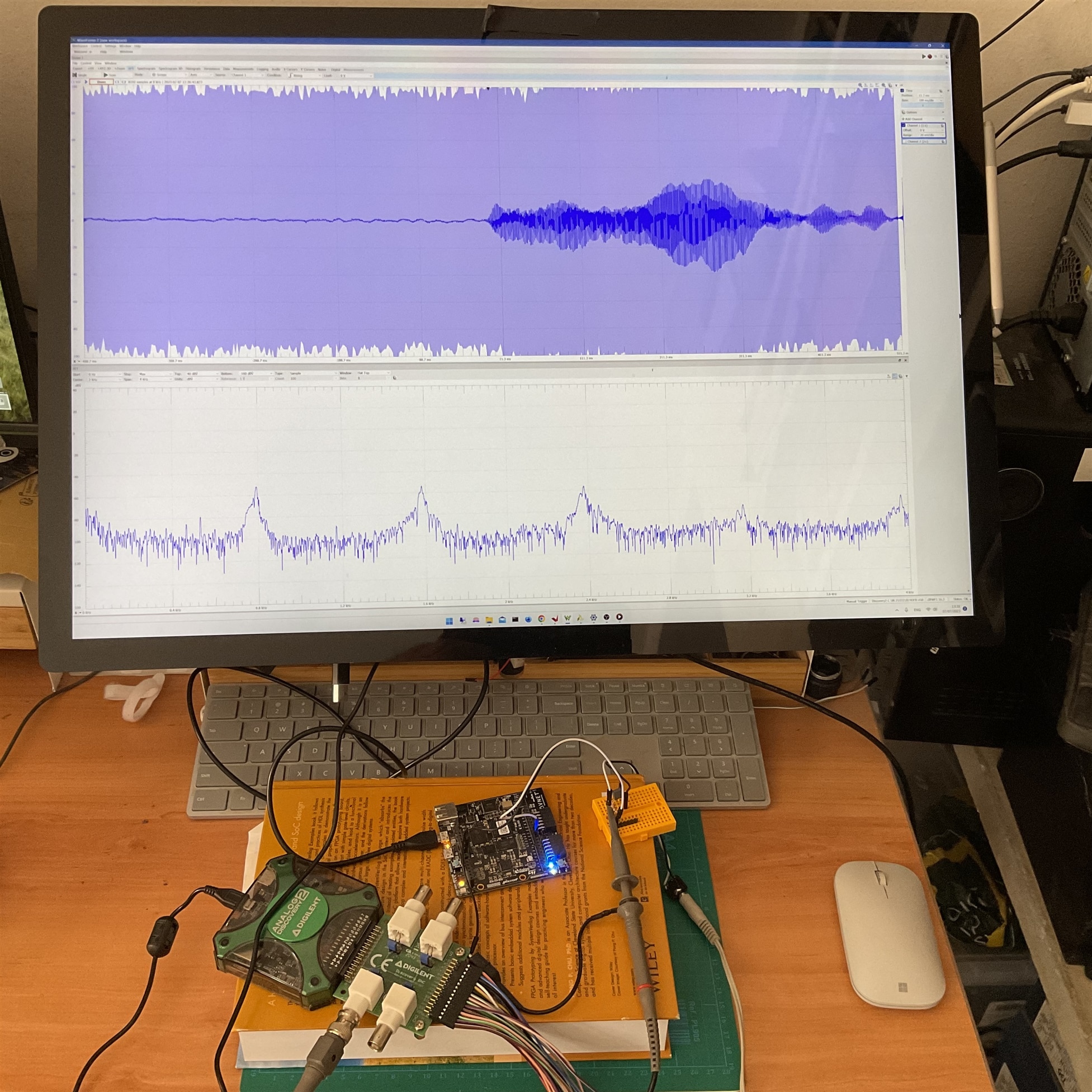
A short video demonstration capturing the sound of a recorder.
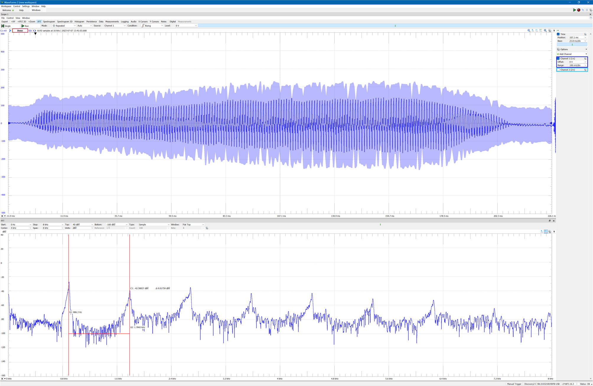
Digilent Analog Discovery 2 Oscilloscope
View on the oscilloscope of the waveform produced by the sound of the recorder playing a single note.
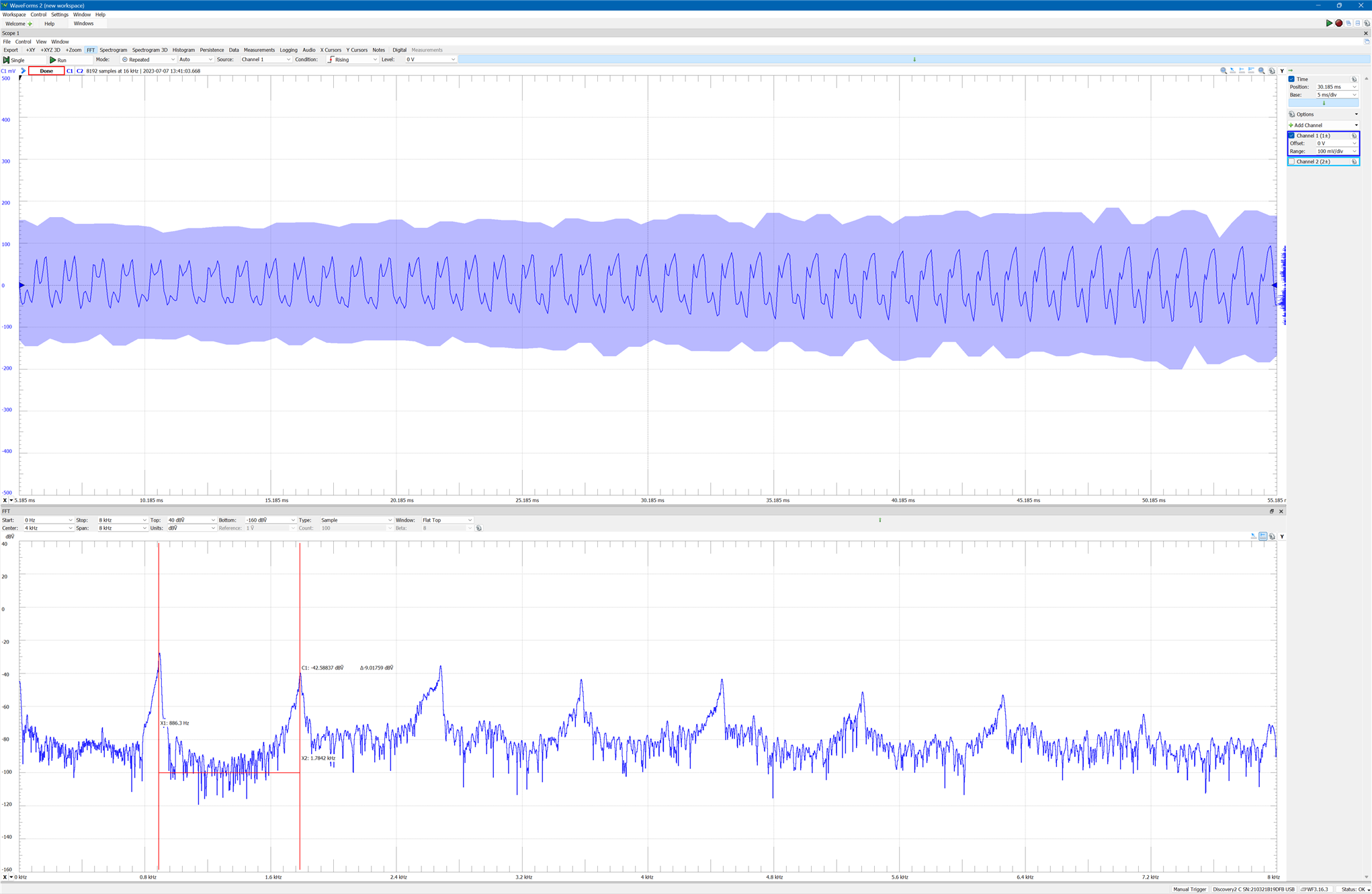
Zoom of the wave image. We can see the characteristic shape of the wave that produces the characteristic sound of the recorder.
PDM to PCM decimation
A signal that is coded as PDM can be converted to PCM by sampling it at a lower rate (decimating) and increasing the word length. The ratio of the PDM bit rate to the decimated PCM sample rate is called the oversampling ratio. The decimation (also called "down-sampling") operation, means discard all but every Rth sample.
Vivado includes a Cascaded Integrator Comb (CIC) Compiler. The Cascaded Integrator Comb (CIC) Compiler provides the ability to design and implement AXI4-Stream-compliant cascaded
integrator-comb (CIC) filters. https://docs.xilinx.com/v/u/en-US/pg140-cic-compiler
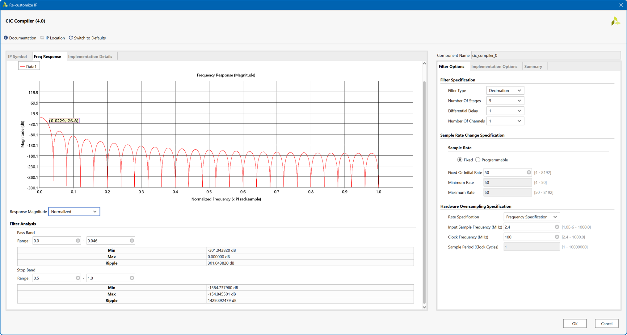
In order to make the PDM to PCM conversion we need to establish our design requirements. Our PDM input sample rate is 2.400 MHz and we want a PCM output sample rate of 48kHz.That is a decimation rate of 50.
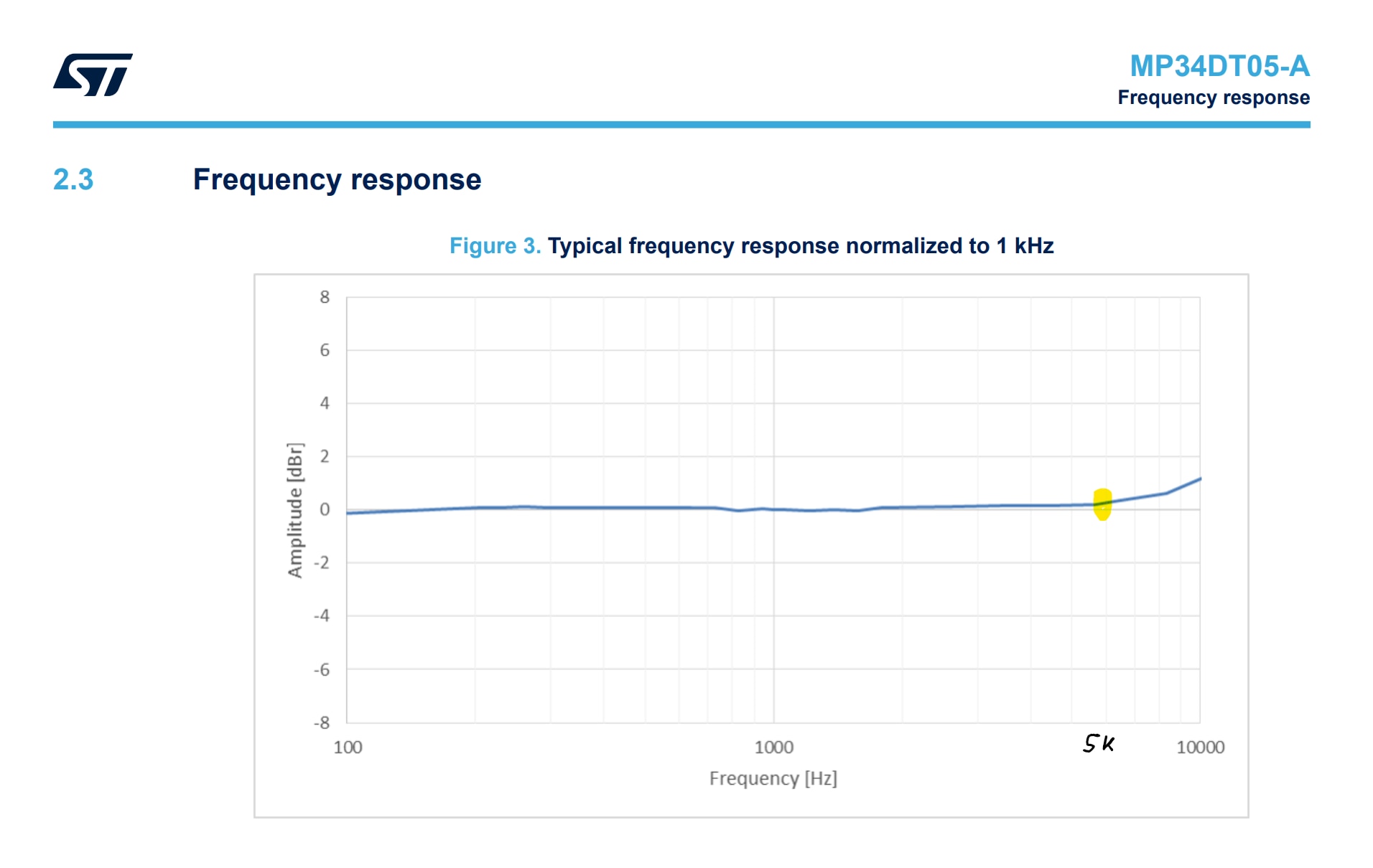
The frequency response is only flat between 100Hz and 4.5kHz, after which it starts going up. So set the pass band filter specification from 0 to 6 kHz and the stop band to 10kHz.
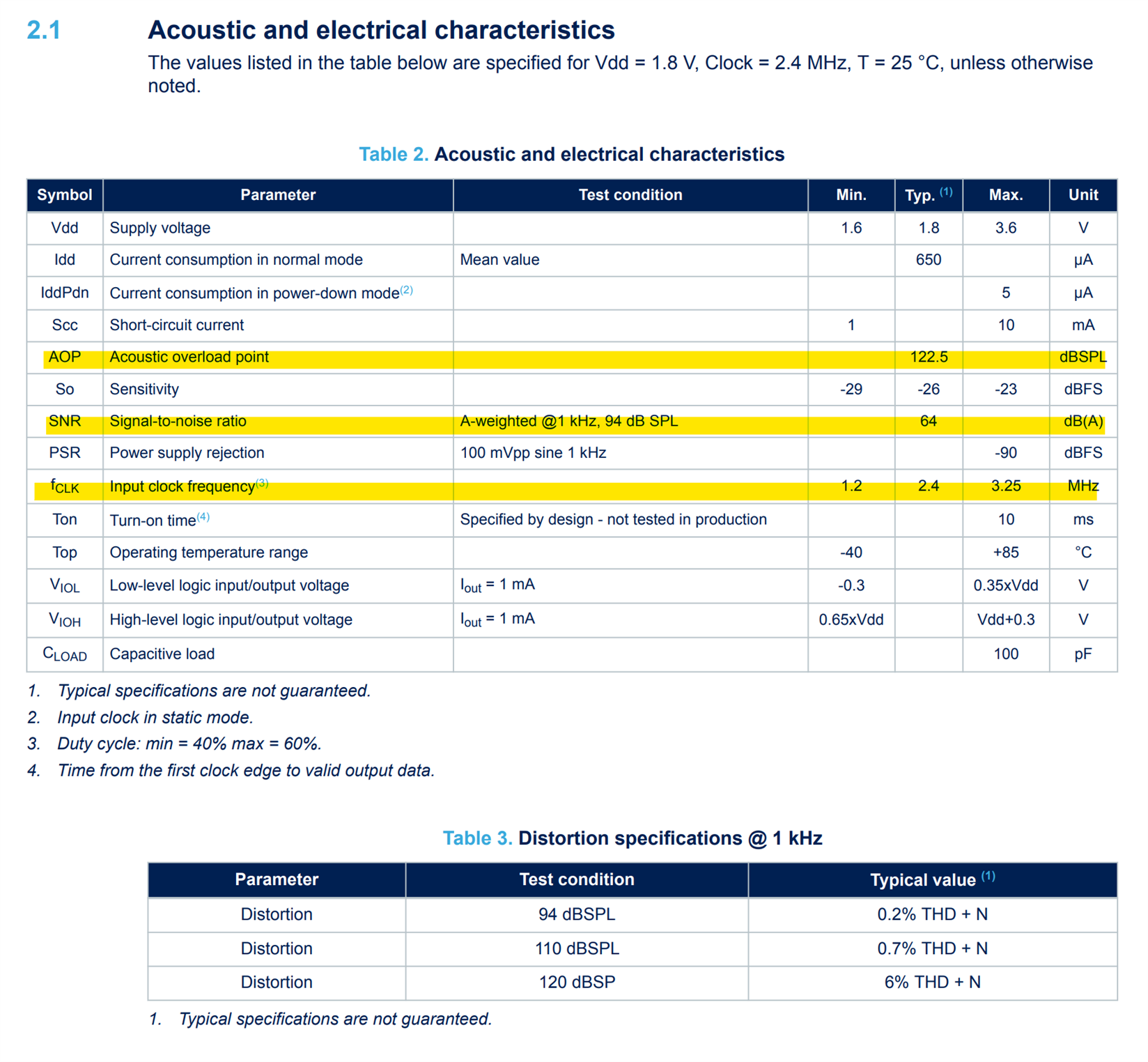
Other requirements can be the pass band ripple and the stop band attenuation for that we need to study the acoustic characteristics of out microphone.
Cascading Integrating Comb Filter
Cascaded Integrator-Comb (CIC) filtrs , also known as Hogenauer filters, are implementations of narrowband lowpass filters. These multirate filters are typically employed in applications that the system sample rate is much larger than the bandwidth occupied by the processed signal as in digital down converters (DDC). Compared to standard FIR filters, they are more economical since they do not include multipliers and use limited storage components. CIC use only adders, subtracters and delay elements.
In a decimating CIC, the input signal is fed through one or more cascaded integrators, then a down-sampler, followed by one or more comb sections (equal in number to the number of integrators). CIC are well suited for antialiasing filtering prior to decimation or sample rate reduction.
Configuration of the AMD LogiCORE IP CIC Compiler
The AMD LogiCORE IP CIC Compiler core provides the ability to design and implement AXI4-Stream-compliant cascaded integrator-comb (CIC) filters.
We will choose a Decimation Filter with 5 stages, one channel and a 50 rate change factor. Finally we will indicate the input sampling rate and the expected clock frequency. The last will be used to determine the potential for folding in the CIC filter implementation. We can also review the expected frequency response
Once configured our CIC we can instantiate it form a SystemVerilog module:
`timescale 1ns / 1ps

module pdm_microphone
  #(
    parameter INPUT_FREQ = 100000000,
    parameter PDM_FREQ = 2400000

    )
   (
    input         clk,
    input         rst,

    output [31:0] mic_pcm_data,
    output        mic_data_valid,


    output        mic_clk,
    input         mic_pdm_data,
    output        mic_lrsel

    );

   logic [2:0]      data_reg;
   logic            clk_rising;


   always_ff@(posedge clk) begin
      if (rst) begin
         data_reg       <= 0;

      end
      else begin
         data_reg[0]   <= mic_pdm_data;
         data_reg[2:1] <= data_reg[1:0];

      end
   end

   // clock gen
   pdm_clk_gen
     #(
       .INPUT_FREQ(INPUT_FREQ),
       .OUTPUT_FREQ(PDM_FREQ)

       )
   pdm_clk_gen_i
     (
      .clk(clk),
      .rst(rst),

      .mic_clk(mic_clk),
      .clk_rising(clk_rising)

      );

   logic [31:0] cic_out_data;
   logic        cic_out_valid;

   cic_compiler_0 cic_compiler
     (
      .aclk(clk),                                // input wire aclk
      .s_axis_data_tdata({7'b0,data_reg[2]}),    // input wire [7 : 0] s_axis_data_tdata
      .s_axis_data_tvalid(clk_rising),           // input wire s_axis_data_tvalid
      .s_axis_data_tready(),                     // output wire s_axis_data_tready

      .m_axis_data_tdata(cic_out_data),         // output wire [31 : 0] m_axis_data_tdata
      .m_axis_data_tvalid(cic_out_valid)        // output wire m_axis_data_tvalid
      );


   assign mic_lrsel = 0;
   assign mic_pcm_data = cic_out_data;
   assign mic_data_valid = cic_out_valid;

endmodule
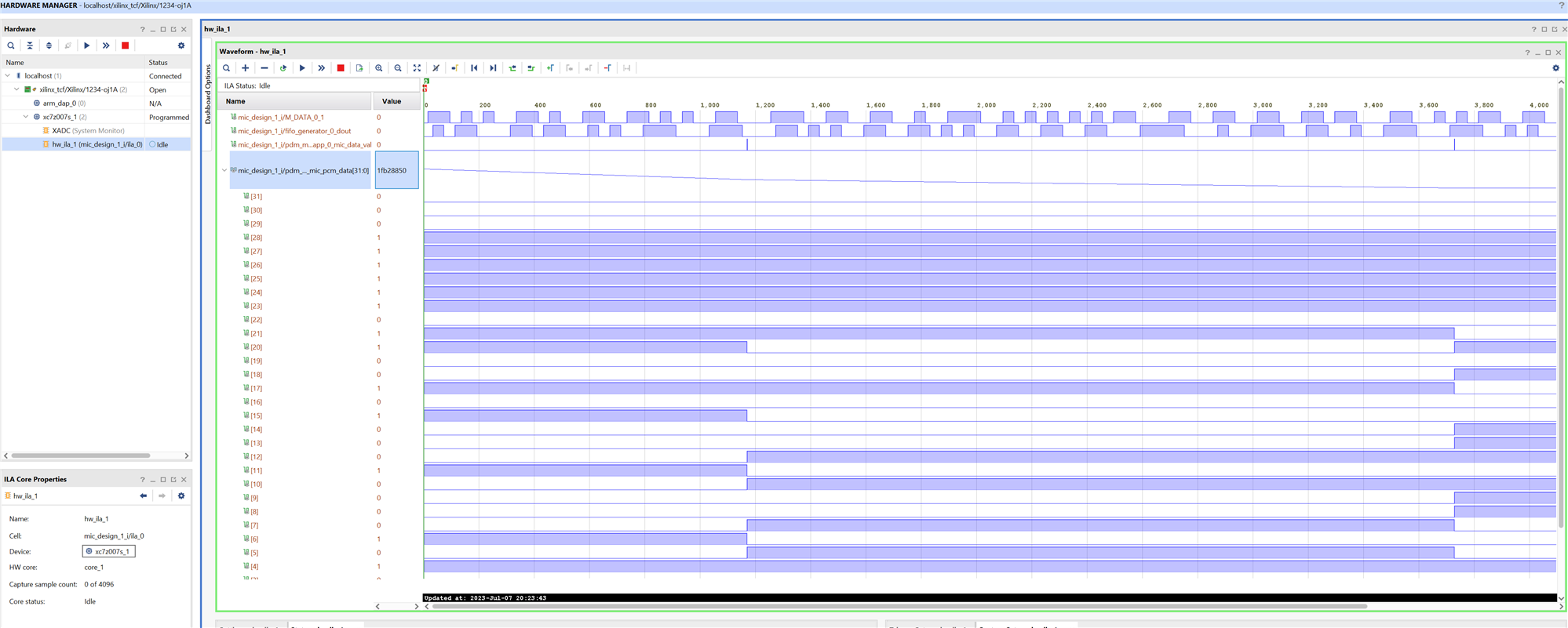
Using the Integrated Logic Analyzer (ILA) we can view the PCM output
Conclusion
I wanted to explore the possibility of using the microphone from the Minized development board for the final project and the results have been satisfactory.
Now I will start to see how to convert that PCM signal into an AES3 signal in order to transmit the sound using an I2S interface. Vivado also provides sound format conversion and I2S transmitters and receivers.
References
- https://www.dsprelated.com/showarticle/1337.php
- https://tomverbeure.github.io/2020/12/20/Design-of-a-Multi-Stage-PDM-to-PCM-Decimation-Pipeline.html
- https://tomverbeure.github.io/2020/10/04/PDM-Microphones-and-Sigma-Delta-Conversion.html
- https://docs.xilinx.com/v/u/en-US/pg140-cic-compiler
- FIR Compiler (xilinx.com)
- FPGA Audio to my PC over Ethernet! PDM Microphone and CIC filter explained!
Path to Programmable III Training Blog Series
- BLOG 1: P2P3 Getting Started. Clockless Hardware Blinky on the Avnet Minized
- BLOG 2: P2P3 AMD Vitis portability and reuse. Migrating a Microblaze bare metal environmental monitor App to the Zynq architecture.
- BLOG 3: P2P3 AMD Zynq-7000 SoC XADC. External Multiplexer Mode.
- BLOG 4: P2P3 AMD Vivado Cascaded Integrator Comb (CIC) Compiler. PDM Microphone to PCM Decimation
- BLOG 5: P2P3 Wireless sensors on the Avnet Minized. Getting Started with PetaLinux
- FINAL PROJECT: AMD Zynq SoC MIDI Vintage Sound Synthesizer - Final
-

navadeepganeshu
-
Cancel
-
Vote Up
0
Vote Down
-
-
Sign in to reply
-
More
-
Cancel
Comment-

navadeepganeshu
-
Cancel
-
Vote Up
0
Vote Down
-
-
Sign in to reply
-
More
-
Cancel
Children