Path to Programmable III Intro
This is the first blog of my participation in the element14 Path to Programmable III program.
I have chosen the MiniZed development board for my participation. I have never worked with Zynq processors before and the Minized board, although it is not already in production, it seemed to me a good way to start developing systems that combine Programmable Logic (PL) and a Processor System (PS) such as the AMD Zynq.
Of the four design paths in the program I chose the DSP theme of "The Core Technology Path". I want to experiment with music sound synthesis and sound processing.
In this blog I will design a clockless manual hardware blinky and will describe my first impressions about the Kit comparing it with other FPGA boards that I already know.
Table of Contents
- Path to Programmable III Intro
- Clockless Manual Hardware Blinky
- The MiniZed Starter Kit
- Clocked Blinky Version
- Summary
- References
Clockless Manual Hardware Blinky
As a first experiment with the Avnet Minized board I have proposed to synthesize in the programmable logic of the Minized board a circuit that blinks a led. Unfortunately the Minized board does not have any clock signals that are not dependent on the Zynq PS. One may be tempted to generate a ring oscillator but this is not a good idea on an FPGA. I had two alternatives, use an external clock signal or simulate the clock transitions with the only switch accessible on the board from the programmable logic. That last option is the one I have used.
Using Systemverilog as hardware description language (HDL) this is the main module.
`timescale 1ns / 1ps

module manual_blinky(
    input logic PL_SW,
    output logic PL_LED_G,
    output logic PL_LED_R

    );

reg r_sw=0;

wire w_xor_sw=(r_sw ^ PL_SW);

typedef enum {OFF, RED, GREEN, RED_GREEN} state_type;

state_type state_reg;
state_type state_next;

logic red_state;
logic green_state;

always_ff @(posedge w_xor_sw)
begin
    r_sw = ~r_sw;
    state_reg <= state_next;
end

always_comb
begin
    state_next = state_reg;
    case (state_reg)
        OFF: begin
               green_state =  1'b0;
               red_state =  1'b0;
               state_next = RED;
             end
        RED: begin
               green_state =  1'b0;
               red_state =  1'b1;
               state_next = GREEN;
             end
        GREEN: begin
               green_state =  1'b1;
               red_state =  1'b0;
               state_next = RED_GREEN;
             end
        RED_GREEN: begin
               green_state =  1'b1;
               red_state =  1'b1;
               state_next = OFF;
             end
    endcase
end

assign PL_LED_R = red_state;
assign PL_LED_G = green_state;

endmodule
It defines a finite state machine that goes through four possible states. Turn off the two elements of the bi-element LED, turn on the red element, turn on the green element, turn on both elements and start again with both elements off.
The circuit uses
- PL User Switch
- PL bi-element LED: RED and GREEN LEDs
The clock is simulated by converting the two PL User Switch transitions to positive edges of a virtual clock.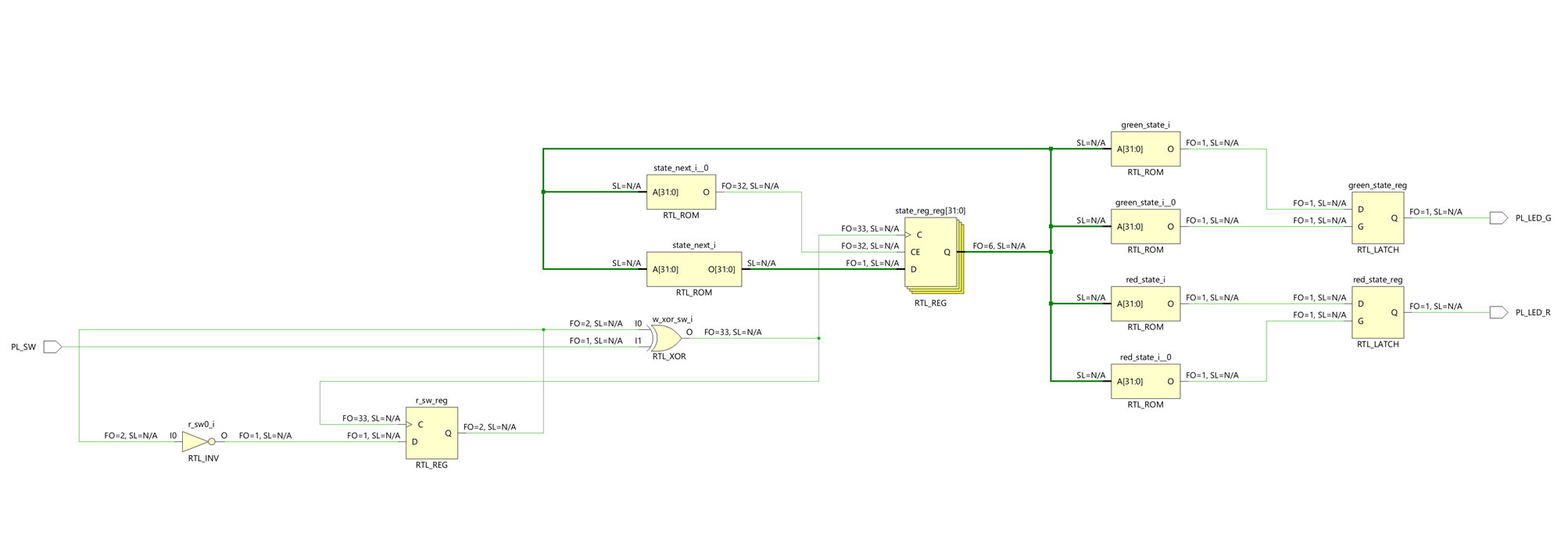
The circuit in action:
The circuit uses the LED and switch connected to the Programable Logic fabric.
The PL LED is a bi-element (red-green) LED and the PL switch is a DIP switch.

XDC file
The XDC file lists all of the FPGA pins that are routed out to physical pins on the board. For this circuit we need to indicate Vivado to which physical pins are connected the PL_LED_G, PL_LED_R output signals and PL_SW input signal.
The systemverilog module references that inputs and outputs and we define the routing in a constraints file set specifically for the Minized board hardware.
set_property PACKAGE_PIN E13 [get_ports PL_LED_G]
set_property IOSTANDARD LVCMOS33 [get_ports PL_LED_G]

set_property PACKAGE_PIN E12 [get_ports PL_LED_R]
set_property IOSTANDARD LVCMOS33 [get_ports PL_LED_R]

set_property PACKAGE_PIN E11 [get_ports PL_SW]
set_property IOSTANDARD LVCMOS33 [get_ports PL_SW]
Program the Device with Vivado 2022.2
I have used the version of Vivado that I had already installed on my Windows 11 Pro machine. This is version 2022.2 ML Edition of AMD Vivado.
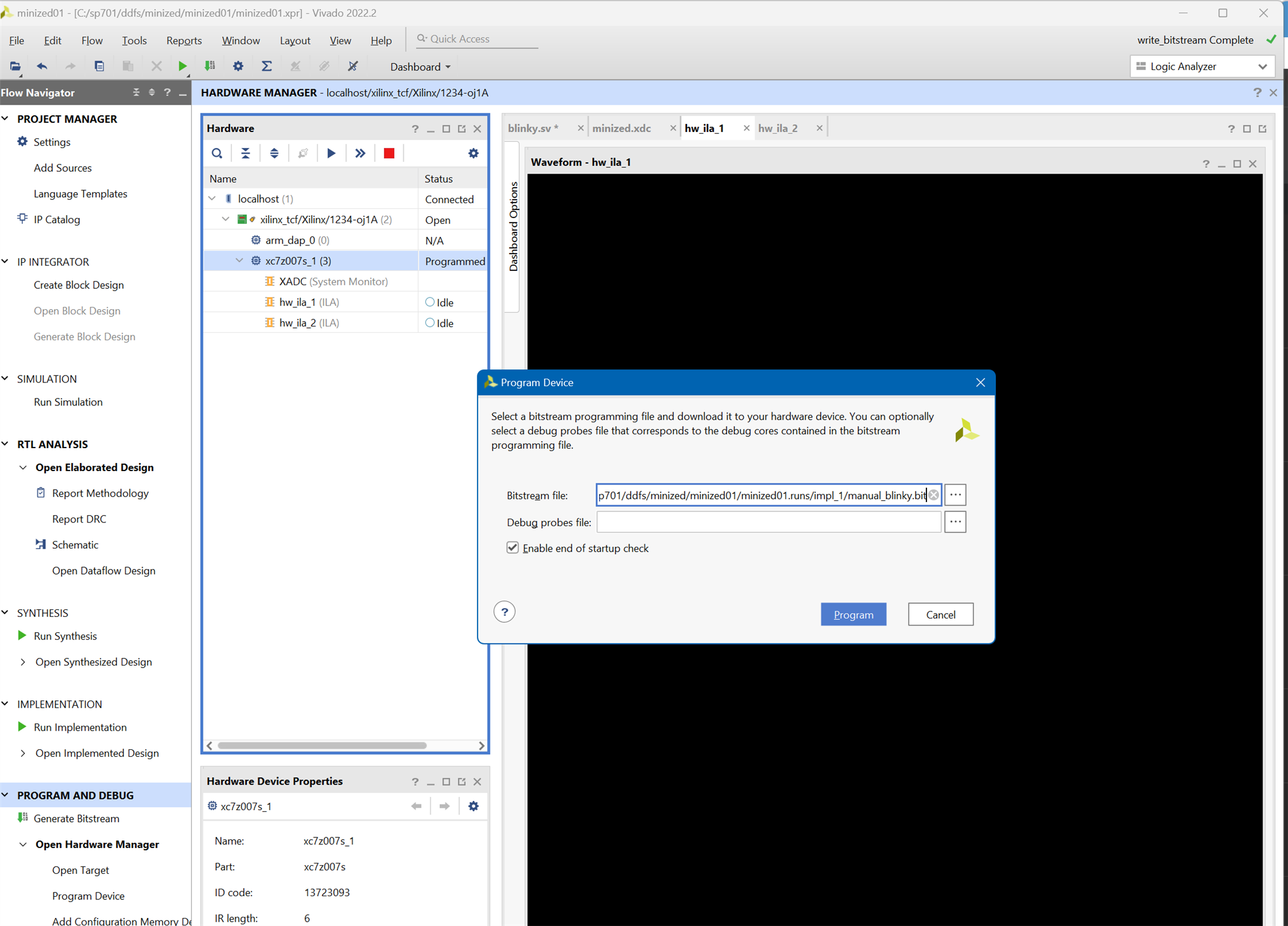
From Vivado we can program the Programmable Logic fabric of the AMD Zynq.
First we need to create a bitstream programming file file and then use the hardware manager to connect with the Minized and download the file to it.
The MiniZed Starter Kit
For my training path I chose the Avnet Minized development board. Let's see what's in the kit sent free of charge by the two sponsors of the training: AMD and element14.
What is inside the box
- The MiniZed development board
- A Voucher for SDSoC license from Xilinx
- A Micro USB cable
- Three jumpers
- Quick Start Instruction card
- Safety Instructions pamphlet
I am not very clear about the utility of the jumpers.
The Avnet Minized development board features a Zynq Z7007S, which integrates an Arm Cortex-A9 processor with Xilinx Artix-7 equivalent programmable logic.
You can populate three male headers that are close to the headers compatible with Arduino modules.
- JP1: VCCBAT 1V8
- JP3: PMIC GPIO
- JP2: VBBAT 2V5
The board has two PMOD female connectors. The Pmod interface (peripheral module interface) is an open standard defined by Digilent for connecting peripheral modules to FPGA and microcontroller development boards.
Back side of the board
Identifying PCB Revision
I was worried if the kit I was going to receive was the latest version of the PCB or if it was the first to suffer a problem due to some oversight in the design. So one of the first things I did was check if my board was one of those affected by the problem.
According this Errata Document, MiniZed_Rev1_Errata_v1_0.pdf, the remote JTAG debug reset does not work for rev 1board. The image below indicates how you can verify that you have a MiniZed Rev 1 board.
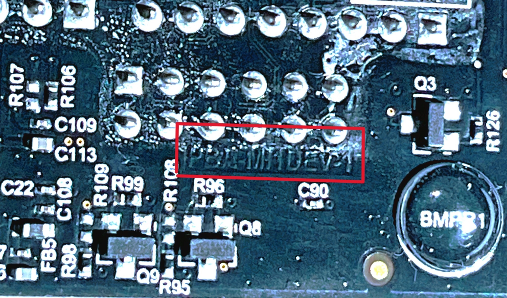
For a Rev 1 board, the text PBA-M1DEV-1 is etched into the copper.
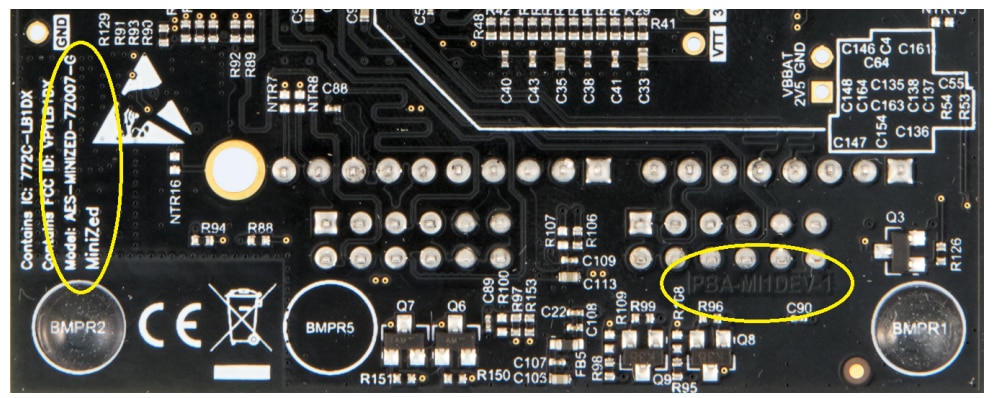
It seems that the board I received is affected by this error.
Both Xilinx Vivado and SDK will be affected when trying to use JTAG remotely. Since the power on reset and software reset cannot be controlled via the FTDI device, the tools will not be able to programmatically issue a reset when re-starting a download. MiniZed is only reset during power on or when the reset button is pushed.
The resistors marked in red below are not on the current schematic. Without them, many boards manifested an unreliable reset on power-up. This was because the inputs to U16 would float when the FTDI chip was not actively driving the LS_OE_N line. Because this line is under software control via the FTDI driver, it is not driven unless debug software is active.
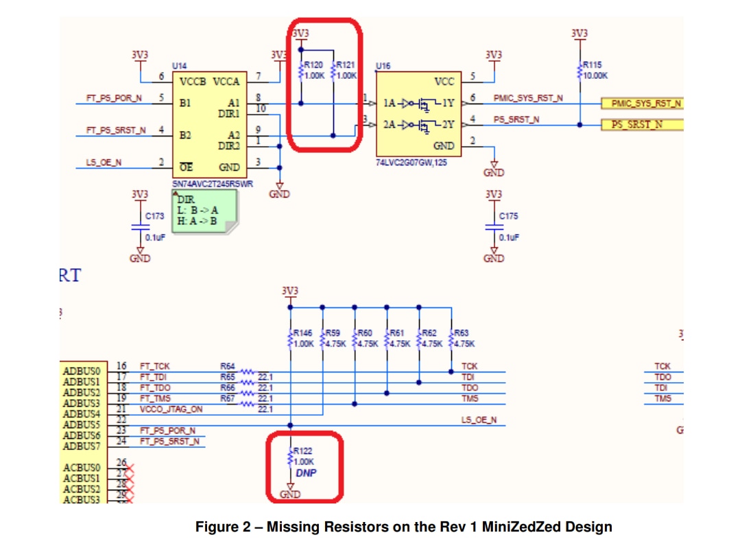
See the Errata document for a workaround.
That being said, affected by the issue or not, I haven't had any weird issues with it so far.
AMD Zynq Single Core SoC XC7Z007S-1 CLG225C
The Avnet Minized development board features an AMD Zynq Single Core SoC XC7Z007S-1 CLG225C
- Manufacturer: AMD XILINX
- Manufacturer Part No: XC7Z007S-1CLG225C
- Newark Part No.: 32AC9828
- Product Range Zynq Family 7000S Series Microprocessors
- Technical Datasheet: XC7Z007S-1CLG225C Datasheet
References:
- XC7Z007S-1CLG225C Amd Xilinx, Microprocesador PSoC / MPSoC, Familia Zynq-7000, ARM Cortex-A9 | Farnell ES
- ds190-Zynq-7000-Overview.pdf • Viewer • AMD Adaptive Computing Documentation Portal (xilinx.com)
The XC7Z007S is the humblest of the Zynq-7000 family. It a single-core member of the Xilinx Zynq-7000 family of System-on-Chip (SoC) devices. It combines a single-core ARM Cortex-A9 processor with programmable logic in a single chip, offering a powerful and flexible platform for embedded system designs.
Processing System:
- Single-core ARM Cortex-A9 processor running at up to 667 MHz.
- Floating-point unit (FPU) for enhanced numerical processing capabilities.
- 32 KB instruction and data caches for efficient data access.
- Memory management unit (MMU) for virtual memory support.
- JTAG debug support for software debugging.
Programmable Logic (PL):
- Contains the Xilinx 7-series Artix-7 FPGA fabric, allowing for custom logic implementation.
- Configurable logic blocks (CLBs) for flexible digital circuitry implementation.
- Dedicated DSP slices for high-performance digital signal processing.
- Block RAM (BRAM) resources for efficient data storage and memory implementation.
- Various I/O resources, such as GPIOs, serializers, and transceivers, for connectivity.
Memory and Interfaces:
- On-chip memory resources, including on-chip RAM and BRAM.
- External memory interfaces, such as DDR3 and LPDDR2, for larger data storage.
- Multiple communication interfaces, including UART, SPI, I2C, CAN, and Ethernet.
- USB ports for connecting external devices.
System Integration:
- Advanced power management capabilities for efficient power utilization.
- Interrupt controller for handling and prioritizing system interrupts.
- Real-time clock (RTC) for timekeeping functionality.
- Programmable timers and watchdog timer for system control and monitoring.
- Direct Memory Access (DMA) controllers for efficient data transfers.
Development Tools and Ecosystem:
- Supported by Xilinx's Vivado Design Suite, providing a comprehensive design flow.
- Vast library of IP cores and software libraries for accelerated development.
- Integration with software development tools, including Xilinx SDK and third-party IDEs.
- Documentation, reference designs, and community support for easy adoption.
Seems that the Zynq XC7Z007S SoC offers a good balance between processing power and programmable logic flexibility, making it suitable for a wide range of embedded system applications.
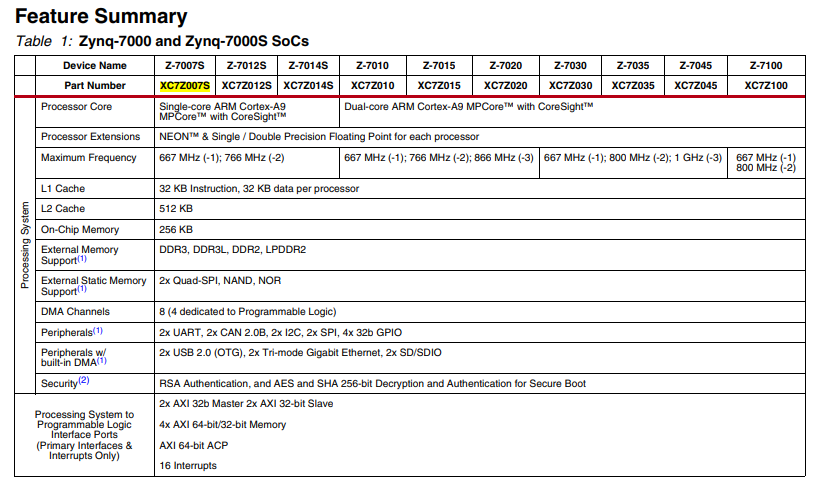
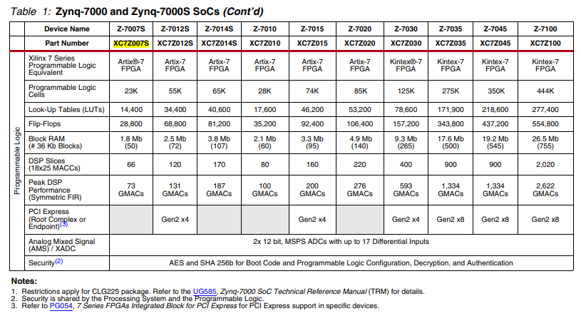
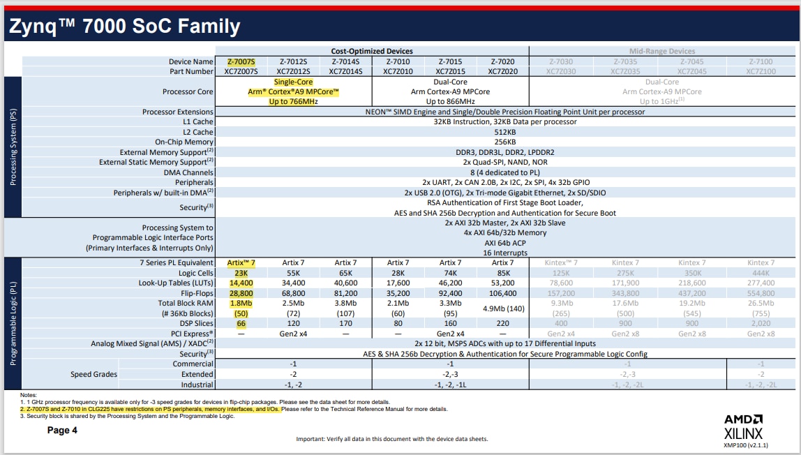
From the AMD Zynq product Selection Guide: cost-optimized-product-selection-guide.pdf • Viewer • AMD Adaptive Computing Documentation Portal (xilinx.com)
Comparing with the XC7S50 Spartan-7 FPGA from the Arty s7 50
The Arty s7 50 is the board that got me started on FPGAs thanks to element14 through the 7 Ways to Leave Your Spartan-6 FPGA program. My participation in that program.
The Spartan 7 does not include an additional microcontroller as it happens with the Zynq family although several models of microcontrollers such as Microblaze or ARM can be synthesized using programmable logic but with worse performance than a particular microcontroller.

The Digilent Arty S7 50 comes with a XC7S50 Spartan 7 FPGA.
It is difficult to make a comparison without having special requirements for an application, but in the summary tables you can see the differences between some of the characteristics of both FPGa fabrics.

Understanding PS Interfaces
One of the things I have had to learn is the different interfaces exposed by the Processing System and by the Programmable Logic. To work with the Zynq we must understand how to access the different interfaces from the Processing System (PS)
PS External Interfaces: The PS external interfaces use dedicated pins that cannot be assigned as PL pins. These include:
- Clock,
- reset,
- boot mode
- and voltage reference
- Up to 54 dedicated multiuse I/O (MIO) pins, software-configurable to connect to any of the internal I/O peripherals and static memory controllers
- 32-bit or 16-bit DDR2/DDR3/DDR3L/LPDDR2 memories
MIO Overview
The function of the MIO is to multiplex access from the PS peripheral and static memory interfaces to the PS pins as defined in the configuration registers.
There are up to 54 pins available for use by the IOP and static memory interfaces in the PS.
EMIO Overview
EMIO: extendable multiplexed I/O. If additional I/O pins beyond the 54 are required, it is possible to route these through the PL to the I/O associated with the PL.
The PS Configuration Wizard (PCW) tool should be used for peripheral and static memory pin mapping.
Licenses included
The Minized kit contains a SDSoC license from Xilinx. Lets redeem the voucher.
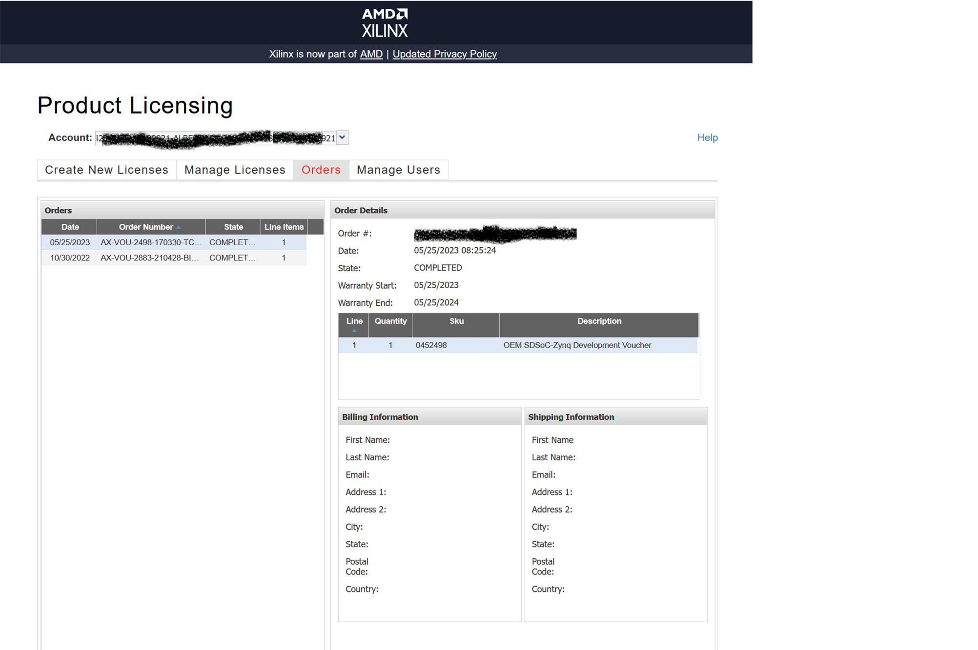
Currently there is an edition of Vivado, the ML Edition that is free and that supports Minized well so it is not necessary to consume the license voucher unless you need to work with old designs that still require that license.
Quick Start Guide
The start guide is very easy to follow, the board comes ready to give us a demonstration of the use of the PDM microphone, the user leds, the I2C sensors and the bluetooth interface.
The www.minized.org is not active now. Everything related to the minized is now in the Avnet site
Console output for reference
Console output when running the Petalinux demo from the Getting Starting Guide:
U-Boot 2016.07 (Jul 13 2017 - 19:58:56 -0700)

DRAM:  ECC disabled 512 MiB
MMC:   sdhci@e0100000: 0, sdhci@e0101000: 1
SF: Detected N25Q128 with page size 256 Bytes, erase size 64 KiB, total 16 MiB
*** Warning - bad CRC, using default environment

In:    serial
Out:   serial
Err:   serial
U-BOOT for

Hit any key to stop autoboot:  0
switch to partitions #0, OK
mmc1(part 0) is current device
reading image.ub
16786800 bytes read in 1551 ms (10.3 MiB/s)
## Loading kernel from FIT Image at 10000000 ...
   Using 'conf@1' configuration
   Verifying Hash Integrity ... OK
   Trying 'kernel@0' kernel subimage
     Description:  Linux Kernel
     Type:         Kernel Image
     Compression:  uncompressed
     Data Start:   0x100000d4
     Data Size:    4075112 Bytes = 3.9 MiB
     Architecture: ARM
     OS:           Linux
     Load Address: 0x00008000
     Entry Point:  0x00008000
     Hash algo:    sha1
     Hash value:   2feb6a2f50fc863208748d4a4a5502fce93487d9
   Verifying Hash Integrity ... sha1+ OK
## Loading ramdisk from FIT Image at 10000000 ...
   Using 'conf@1' configuration
   Trying 'ramdisk@0' ramdisk subimage
     Description:  ramdisk
     Type:         RAMDisk Image
     Compression:  uncompressed
     Data Start:   0x103e72e0
     Data Size:    12693150 Bytes = 12.1 MiB
     Architecture: ARM
     OS:           Linux
     Load Address: unavailable
     Entry Point:  unavailable
     Hash algo:    sha1
     Hash value:   acf68a35f1d97f744aa8672737a4616de57bb555
   Verifying Hash Integrity ... sha1+ OK
## Loading fdt from FIT Image at 10000000 ...
   Using 'conf@1' configuration
   Trying 'fdt@0' fdt subimage
     Description:  Flattened Device Tree blob
     Type:         Flat Device Tree
     Compression:  uncompressed
     Data Start:   0x103e3030
     Data Size:    16894 Bytes = 16.5 KiB
     Architecture: ARM
     Hash algo:    sha1
     Hash value:   d989058f04e066702a50da837782f2c5ed94e7b8
   Verifying Hash Integrity ... sha1+ OK
   Booting using the fdt blob at 0x103e3030
   Loading Kernel Image ... OK
   Loading Ramdisk to 073e5000, end 07fffe9e ... OK
   Loading Device Tree to 073dd000, end 073e41fd ... OK

Starting kernel ...

Uncompressing Linux... done, booting the kernel.
Booting Linux on physical CPU 0x0
Linux version 4.6.0-xilinx (training@localhost.localdomain) (gcc version 5.2.1 20151005 (Linaro GCC 5.2-2015.11-2) ) #1 SMP PREEMPT Tue Jun 6 20:15:27 PDT 2017
CPU: ARMv7 Processor [413fc090] revision 0 (ARMv7), cr=18c5387d
CPU: PIPT / VIPT nonaliasing data cache, VIPT aliasing instruction cache
Machine model: minized
bootconsole [earlycon0] enabled
cma: Reserved 16 MiB at 0x1f000000
Memory policy: Data cache writealloc
percpu: Embedded 12 pages/cpu @debca000 s19776 r8192 d21184 u49152
Built 1 zonelists in Zone order, mobility grouping on.  Total pages: 130048
Kernel command line: console=ttyPS0,115200 earlyprintk
PID hash table entries: 2048 (order: 1, 8192 bytes)
Dentry cache hash table entries: 65536 (order: 6, 262144 bytes)
Inode-cache hash table entries: 32768 (order: 5, 131072 bytes)
Memory: 480056K/524288K available (6319K kernel code, 249K rwdata, 1916K rodata, 1024K init, 212K bss, 27848K reserved, 16384K cma-reserved, 0K highmem)
Virtual kernel memory layout:
    vector  : 0xffff0000 - 0xffff1000   (   4 kB)
    fixmap  : 0xffc00000 - 0xfff00000   (3072 kB)
    vmalloc : 0xe0800000 - 0xff800000   ( 496 MB)
    lowmem  : 0xc0000000 - 0xe0000000   ( 512 MB)
    pkmap   : 0xbfe00000 - 0xc0000000   (   2 MB)
    modules : 0xbf000000 - 0xbfe00000   (  14 MB)
      .text : 0xc0008000 - 0xc090ae84   (9228 kB)
      .init : 0xc0a00000 - 0xc0b00000   (1024 kB)
      .data : 0xc0b00000 - 0xc0b3e7a0   ( 250 kB)
       .bss : 0xc0b3e7a0 - 0xc0b73a38   ( 213 kB)
Preemptible hierarchical RCU implementation.
        Build-time adjustment of leaf fanout to 32.
        RCU restricting CPUs from NR_CPUS=4 to nr_cpu_ids=2.
RCU: Adjusting geometry for rcu_fanout_leaf=32, nr_cpu_ids=2
NR_IRQS:16 nr_irqs:16 16
efuse mapped to e0800000
slcr mapped to e0802000
L2C: platform modifies aux control register: 0x72360000 -> 0x72760000
L2C: DT/platform modifies aux control register: 0x72360000 -> 0x72760000
L2C-310 erratum 769419 enabled
L2C-310 enabling early BRESP for Cortex-A9
L2C-310 full line of zeros enabled for Cortex-A9
L2C-310 ID prefetch enabled, offset 1 lines
L2C-310 dynamic clock gating enabled, standby mode enabled
L2C-310 cache controller enabled, 8 ways, 512 kB
L2C-310: CACHE_ID 0x410000c8, AUX_CTRL 0x76760001
zynq_clock_init: clkc starts at e0802100
Zynq clock init
sched_clock: 64 bits at 333MHz, resolution 3ns, wraps every 4398046511103ns
clocksource: arm_global_timer: mask: 0xffffffffffffffff max_cycles: 0x4ce07af025, max_idle_ns: 440795209040 ns
Switching to timer-based delay loop, resolution 3ns
clocksource: ttc_clocksource: mask: 0xffff max_cycles: 0xffff, max_idle_ns: 537538477 ns
timer #0 at e080a000, irq=17
Console: colour dummy device 80x30
Calibrating delay loop (skipped), value calculated using timer frequency.. 666.66 BogoMIPS (lpj=3333333)
pid_max: default: 32768 minimum: 301
Mount-cache hash table entries: 1024 (order: 0, 4096 bytes)
Mountpoint-cache hash table entries: 1024 (order: 0, 4096 bytes)
CPU: Testing write buffer coherency: ok
CPU0: thread -1, cpu 0, socket 0, mpidr 80000000
Setting up static identity map for 0x100000 - 0x100058
CPU1: failed to boot: -1
Brought up 1 CPUs
SMP: Total of 1 processors activated (666.66 BogoMIPS).
CPU: All CPU(s) started in SVC mode.
devtmpfs: initialized
VFP support v0.3: implementor 41 architecture 3 part 30 variant 9 rev 4
clocksource: jiffies: mask: 0xffffffff max_cycles: 0xffffffff, max_idle_ns: 19112604462750000 ns
pinctrl core: initialized pinctrl subsystem
NET: Registered protocol family 16
DMA: preallocated 256 KiB pool for atomic coherent allocations
cpuidle: using governor menu
hw-breakpoint: found 5 (+1 reserved) breakpoint and 1 watchpoint registers.
hw-breakpoint: maximum watchpoint size is 4 bytes.
zynq-ocm f800c000.ocmc: ZYNQ OCM pool: 256 KiB @ 0xe0880000
zynq-pinctrl 700.pinctrl: zynq pinctrl initialized
GPIO IRQ not connected
XGpio: /amba_pl/gpio@41200000: registered, base is 905
GPIO IRQ not connected
XGpio: /amba_pl/gpio@41200000: dual channel registered, base is 904
GPIO IRQ not connected
XGpio: /amba_pl/gpio@41210000: registered, base is 903
GPIO IRQ not connected
XGpio: /amba_pl/gpio@41220000: registered, base is 895
vgaarb: loaded
SCSI subsystem initialized
usbcore: registered new interface driver usbfs
usbcore: registered new interface driver hub
usbcore: registered new device driver usb
media: Linux media interface: v0.10
Linux video capture interface: v2.00
pps_core: LinuxPPS API ver. 1 registered
pps_core: Software ver. 5.3.6 - Copyright 2005-2007 Rodolfo Giometti <giometti@linux.it>
PTP clock support registered
EDAC MC: Ver: 3.0.0
Advanced Linux Sound Architecture Driver Initialized.
Bluetooth: Core ver 2.21
NET: Registered protocol family 31
Bluetooth: HCI device and connection manager initialized
Bluetooth: HCI socket layer initialized
Bluetooth: L2CAP socket layer initialized
Bluetooth: SCO socket layer initialized
clocksource: Switched to clocksource arm_global_timer
NET: Registered protocol family 2
TCP established hash table entries: 4096 (order: 2, 16384 bytes)
TCP bind hash table entries: 4096 (order: 3, 32768 bytes)
TCP: Hash tables configured (established 4096 bind 4096)
UDP hash table entries: 256 (order: 1, 8192 bytes)
UDP-Lite hash table entries: 256 (order: 1, 8192 bytes)
NET: Registered protocol family 1
RPC: Registered named UNIX socket transport module.
RPC: Registered udp transport module.
RPC: Registered tcp transport module.
RPC: Registered tcp NFSv4.1 backchannel transport module.
Trying to unpack rootfs image as initramfs...
Freeing initrd memory: 12396K (c73e5000 - c8000000)
hw perfevents: enabled with armv7_cortex_a9 PMU driver, 7 counters available
futex hash table entries: 512 (order: 3, 32768 bytes)
workingset: timestamp_bits=28 max_order=17 bucket_order=0
jffs2: version 2.2. (NAND) (SUMMARY)  © 2001-2006 Red Hat, Inc.
io scheduler noop registered
io scheduler deadline registered
io scheduler cfq registered (default)
dma-pl330 f8003000.dmac: Loaded driver for PL330 DMAC-241330
dma-pl330 f8003000.dmac:        DBUFF-128x8bytes Num_Chans-8 Num_Peri-4 Num_Events-16
Serial: 8250/16550 driver, 4 ports, IRQ sharing disabled
43c00000.serial: ttyS0 at MMIO 0x43c01000 (irq = 166, base_baud = 3000000) is a 16550A
e0000000.serial: ttyPS1 at MMIO 0xe0000000 (irq = 143, base_baud = 6249999) is a xuartps
e0001000.serial: ttyPS0 at MMIO 0xe0001000 (irq = 144, base_baud = 6249999) is a xuartps
▒console [ttyPS0] enabled
console [ttyPS0] enabled
bootconsole [earlycon0] disabled
bootconsole [earlycon0] disabled
xdevcfg f8007000.devcfg: ioremap 0xf8007000 to e081e000
[drm] Initialized drm 1.1.0 20060810
brd: module loaded
loop: module loaded
m25p80 spi0.0: found n25q128a13, expected m25p80
m25p80 spi0.0: n25q128a13 (16384 Kbytes)
4 ofpart partitions found on MTD device spi0.0
Creating 4 MTD partitions on "spi0.0":
0x000000000000-0x000000ff0000 : "boot"
0x000000270000-0x000000ff0000 : "kernel"
0x000000ff0000-0x000001000000 : "bootenv"
0x000001000000-0x000001000000 : "spare"
mtd: partition "spare" is out of reach -- disabled
e1000e: Intel(R) PRO/1000 Network Driver - 3.2.6-k
e1000e: Copyright(c) 1999 - 2015 Intel Corporation.
ehci_hcd: USB 2.0 'Enhanced' Host Controller (EHCI) Driver
ehci-pci: EHCI PCI platform driver
usbcore: registered new interface driver usb-storage
e0002000.usb supply vbus not found, using dummy regulator
ULPI transceiver vendor/product ID 0x0424/0x0007
Found SMSC USB3320 ULPI transceiver.
ULPI integrity check: passed.
ci_hdrc ci_hdrc.0: EHCI Host Controller
ci_hdrc ci_hdrc.0: new USB bus registered, assigned bus number 1
ci_hdrc ci_hdrc.0: USB 2.0 started, EHCI 1.00
hub 1-0:1.0: USB hub found
hub 1-0:1.0: 1 port detected
mousedev: PS/2 mouse device common for all mice
i2c /dev entries driver
i2c i2c-0: of_i2c: modalias failure on /amba_pl/i2c@41600000/i2c4@6b
Bluetooth: HCI UART driver ver 2.3
Bluetooth: HCI UART protocol H4 registered
Bluetooth: HCI UART protocol BCSP registered
Bluetooth: HCI UART protocol LL registered
Bluetooth: HCI UART protocol ATH3K registered
Bluetooth: HCI UART protocol Three-wire (H5) registered
EDAC MC: ECC not enabled
Xilinx Zynq CpuIdle Driver started
sdhci: Secure Digital Host Controller Interface driver
sdhci: Copyright(c) Pierre Ossman
sdhci-pltfm: SDHCI platform and OF driver helper
sdhci-arasan e0100000.sdhci: assigned as wifi host
mmc0: SDHCI controller on e0100000.sdhci [e0100000.sdhci] using DMA
mmc1: SDHCI controller on e0101000.sdhci [e0101000.sdhci] using DMA
ledtrig-cpu: registered to indicate activity on CPUs
usbcore: registered new interface driver usbhid
usbhid: USB HID core driver
NET: Registered protocol family 10
sit: IPv6 over IPv4 tunneling driver
NET: Registered protocol family 17
Bluetooth: RFCOMM TTY layer initialized
Bluetooth: RFCOMM socket layer initialized
Bluetooth: RFCOMM ver 1.11
Bluetooth: BNEP (Ethernet Emulation) ver 1.3
Bluetooth: BNEP socket layer initialized
Bluetooth: HIDP (Human Interface Emulation) ver 1.2
Bluetooth: HIDP socket layer initialized
Registering SWP/SWPB emulation handler
mmc1: new high speed MMC card at address 0001
hctosys: unable to open rtc device (rtc0)
wlreg_on: disabling
ALSA device list:
  No soundcards found.
Freeing unused kernel memory: 1024K (c0a00000 - c0b00000)
INIT: mmcblk1boot0: mmc1:0001 Q2J55L partition 1 16.0 MiB
version 2.88 bootingmmcblk1boot1: mmc1:0001 Q2J55L partition 2 16.0 MiB

mmcblk1rpmb: mmc1:0001 Q2J55L partition 3 4.00 MiB
 mmcblk1: p1
FAT-fs (mmcblk1p1): Volume was not properly unmounted. Some data may be corrupt. Please run fsck.
EXT4-fs (mmcblk1rpmb): unable to read superblock
EXT4-fs (mmcblk1rpmb): unable to read superblock
EXT2-fs (mmcblk1rpmb): error: unable to read superblock
FAT-fs (mmcblk1rpmb): unable to read boot sector
EXT4-fs (mmcblk1rpmb): unable to read superblock
EXT4-fs (mmcblk1rpmb): unable to read superblock
EXT2-fs (mmcblk1rpmb): error: unable to read superblock
FAT-fs (mmcblk1rpmb): unable to read boot sector
FAT-fs (mmcblk1rpmb): unable to read boot sector
mount: mounting /dev/mmcblk1rpmb on /run/media/mmcblk1rpmb failed: Input/output error
mount: mounting /dev/mmcblk1boot0 on /run/media/mmcblk1boot0 failed: Invalid argument
mount: mounting /dev/mmcblk1boot1 on /run/media/mmcblk1boot1 failed: Invalid argument
/etc/mdev/mdev-mount.sh: line 28: [: /sys/block/mmcblk1/mmcblk1boot1: binary operator expected
mount: mounting /dev/mmcblk1 on /run/media/mmcblk1 failed: Device or resource busy
random: dd urandom read with 3 bits of entropy available
Fri Jul 14 03:13:01 UTC 2017
Starting internet superserver: inetd.
INIT: Entering runlevel: 5
Configuring network interfaces... ifconfig: SIOCGIFFLAGS: No such device
Starting system message bus: dbus.
Starting Dropbear SSH server: Generating key, this may take a while...
Public key portion is:
ssh-rsa AAAAB3NzaC1yc2EAAAADAQABAAABAQDepc7Flbq7L7wBKbcs9XyEk4+KMO4Jlblc+fHB1ZC/73GUHrAcEzIbXvzPtBJ9agEsfNGM1uF3zkcEpjXF5OYUbX/lJ/STOaGMe+/dnnMwhjFT5JMn9jKGSEfvBpg+T/UFZoc888AyDZYo2yiRMss4kLyDB1dJkY9GY1TwMUvuXQq8WxKHoOdXzhMWlaT68KEsaN/Zot8hmdbQ89ouRI3G5hlu/IK3pUCAJapPgyygnnwzCLcJLH6CNMPtLeGYJZuG/tVAm1hOKifEWhgOW7RptjUzz0nMVd9IsDGZdewPwA5CA0gZxiwIBiwPD3+WI/w8sqeX1E5n9Q+RFHhKh9pR root@plnx_arm
Fingerprint: md5 e0:37:6c:a4:88:5d:13:b1:89:46:7f:3e:94:33:6f:ee
dropbear.
Starting bluetooth
bluetoothd
Starting syslogd/klogd: done
Starting tcf-agent: OK

PetaLinux 2016.4 plnx_arm /dev/ttyPS0

plnx_arm login:
Testing Bluetooth
Entering bt.sh you can tests Bluetooth devices scanning feature
root@plnx_arm:~# bt.sh
#To turn on BT_REG_ON, which is on EMIO GPIO #0
echo 960 > /sys/class/gpio/export
echo out > /sys/class/gpio/gpio960/direction
echo 1 > /sys/class/gpio/gpio960/value
#Set uart0 = serial1 = ttyPS1 baudrate:
#(this was for UART0 from PS) stty -F /dev/ttyPS1 115200
stty -F /dev/ttyS0 115200
sleep 1s
#For the flow control.
#It seems you have to send a character before RTS from the 1DX modulke will be set in the correct state.
#(this was for UART0 from PS) echo "W" > /dev/ttyPS1
echo "W" > /dev/ttyS0
sleep 1s
#Initialize the device:
#(this was for UART0 from PS) hciattach /dev/ttyPS1 bcm43xx 921600 flow -t 10
hciattach /dev/ttyS0 bcm43xx 3000000 flow -t 10
bcm43xx_init
Set Controller UART speed to 3000000 bit/s
Flash firmware /etc/firmware/BCM43430A1.1DX.hcd
Set Controller UART speed to 3000000 bit/s
Device setup complete
sleep 2s

#Configure the right BT device:
hciconfig hci0 up

#begin new
sleep 1s
hciconfig hci0 reset
hciconfig hci0 class 0x200404
#for no password:
hciconfig hci0 sspmode 1
hciconfig hci0 piscan
hciconfig hci0 leadv
hciconfig -a
hci0:   Type: Primary  Bus: UART
        BD Address: 43:43:A1:12:1F:AC  ACL MTU: 1021:8  SCO MTU: 64:1
        UP RUNNING PSCAN ISCAN
        RX bytes:1329 acl:0 sco:0 events:75 errors:0
        TX bytes:1243 acl:0 sco:0 commands:75 errors:0
        Features: 0xbf 0xfe 0xcf 0xfe 0xdb 0xff 0x7b 0x87
        Packet type: DM1 DM3 DM5 DH1 DH3 DH5 HV1 HV2 HV3
        Link policy: RSWITCH SNIFF
        Link mode: SLAVE ACCEPT
        Name: 'MiniZed Murata Type-1DX'
        Class: 0x200404
        Service Classes: Audio
        Device Class: Audio/Video, Device conforms to the Headset profile
        HCI Version: 4.0 (0x6)  Revision: 0x16
        LMP Version: 4.0 (0x6)  Subversion: 0x2209
        Manufacturer: Broadcom Corporation (15)

#end new

sleep 1s
#Scan for BT devices:
hcitool scan
Scanning ...
        70:09:71:9C:FA:3F       [TV] Samsung QN91BA 55
        38:01:95:E1:3D:26       n/a
set +v
root@plnx_arm:~#
Testing I2C sensors
Entering i2c_test.sh the app runs a demonstration that reads motion and temperature sensors.
root@plnx_arm:~# i2c_test.sh
/usr/bin/i2csensor
################################################################################
Testing the MiniZed GPIO and ST Micro LIS2DS12 I2C motion and temperature sensor
--------------------------------------------------------------------------------
The PS Button will reset the LED counter
The PL switch selects the LED count or microphone output on the PL LED
################################################################################
With I2C device address 0x1d received WhoAmI = 0x43
CTL1 = 0x60 written
CTL4 = 0x01 written
gpio903 set as in
gpio906 set as in
gpio958 set as in
gpio959 set as in
gpio904 set as in
gpio905 set as in
gpio895 set as in
gpio896 set as in
 OUT_T register = 0x0b -> Temperature = 36 degrees C.    Acceleration = X:   -81, Y:  -131, Z: +4172
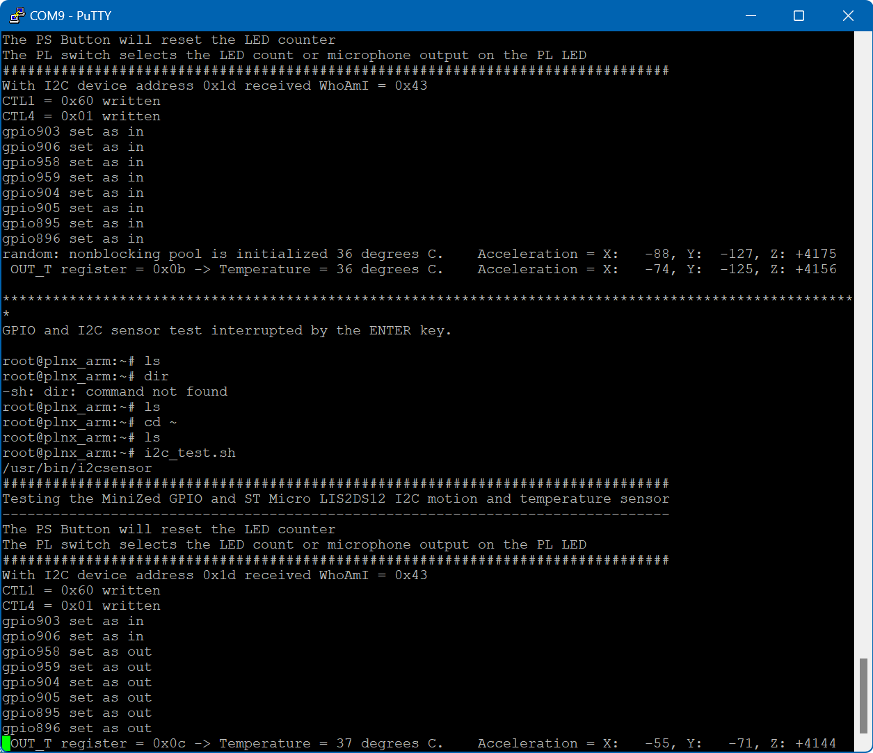
The board executing the preloaded app and hardware definition.
Programmable devices on the Avnet MiniZed
There are three re-programmable devices on the Avnet MiniZed board.
- U7: Microchip 2kbit serial EEPROM, with Part Number 93LC56BT-I/OT
- U2: Micron 128Mbit QSPI NOR flash, with Part Number MT25QL128ABA8E12-1SIT
- U3: Micron 8GB eMMC, with Part Number MTFC8GAKAJCN-4M IT
The EEPROM is programmed in the factory and should not be re-programmed by the user. The content of the EEPROM is proprietary and Avnet does not provide the programming file or support for modifications to its content.
MiniZed re-programming is done in two stages:
- In the first stage the XSCT (Xilinx Software Command-Line Tool) is used to re-program the QSPI flash (U2) so that MiniZed can boot entirely from flash.
- The flash size is limited, so in order to run larger applications (such as Bluetooth), files such as image.ub must be placed into the eMMC memory (U3) instead of in the QSPI flash. The QSPI image is replaced with one that will cause boot to complete by loading image.ub from eMMC. Files for this stage are placed on a USB memory stick that is plugged into MiniZed. Scripts are then executed to format the eMMC, copy over the required files.
From Vivado to add a configuration memory device to the ‘xc7z007s_1’ select the Micron QSPI device of size 128Mb in single width. Then pick the mt25ql128-qspi-x1-single
Using VIVADO to program the device
Vivado Design Suite is a software suite produced by AMD for synthesis and analysis of hardware description language (HDL) designs. Also, we will use Vivado to program the device.
https://www.avnet.com/wps/portal/us/products/avnet-boards/avnet-board-families/minized/
bdf/board.xml at master · Avnet/bdf · GitHub
Vivado knows Avnet's Minized and you can download the board definition from the git repository.
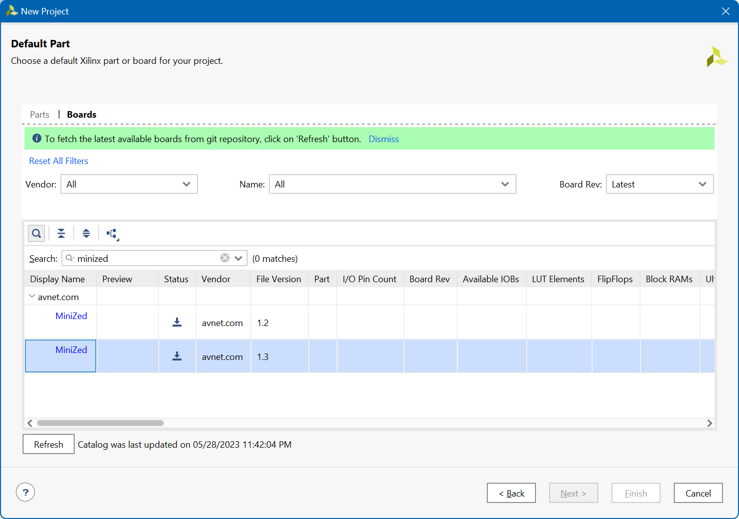
For this demo I downloaded the latest version 1.3
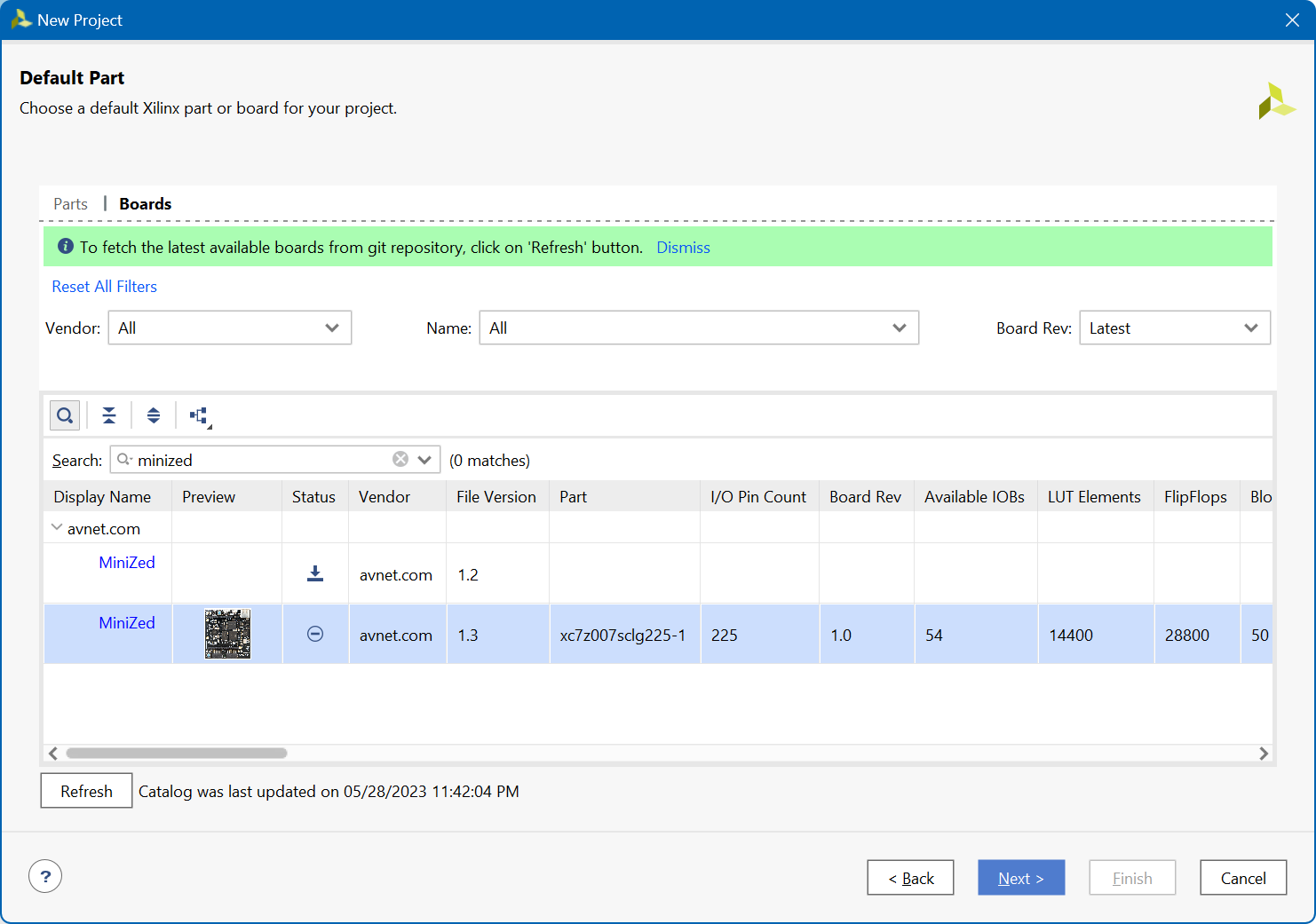
And create a new project in Vivado 2022.2

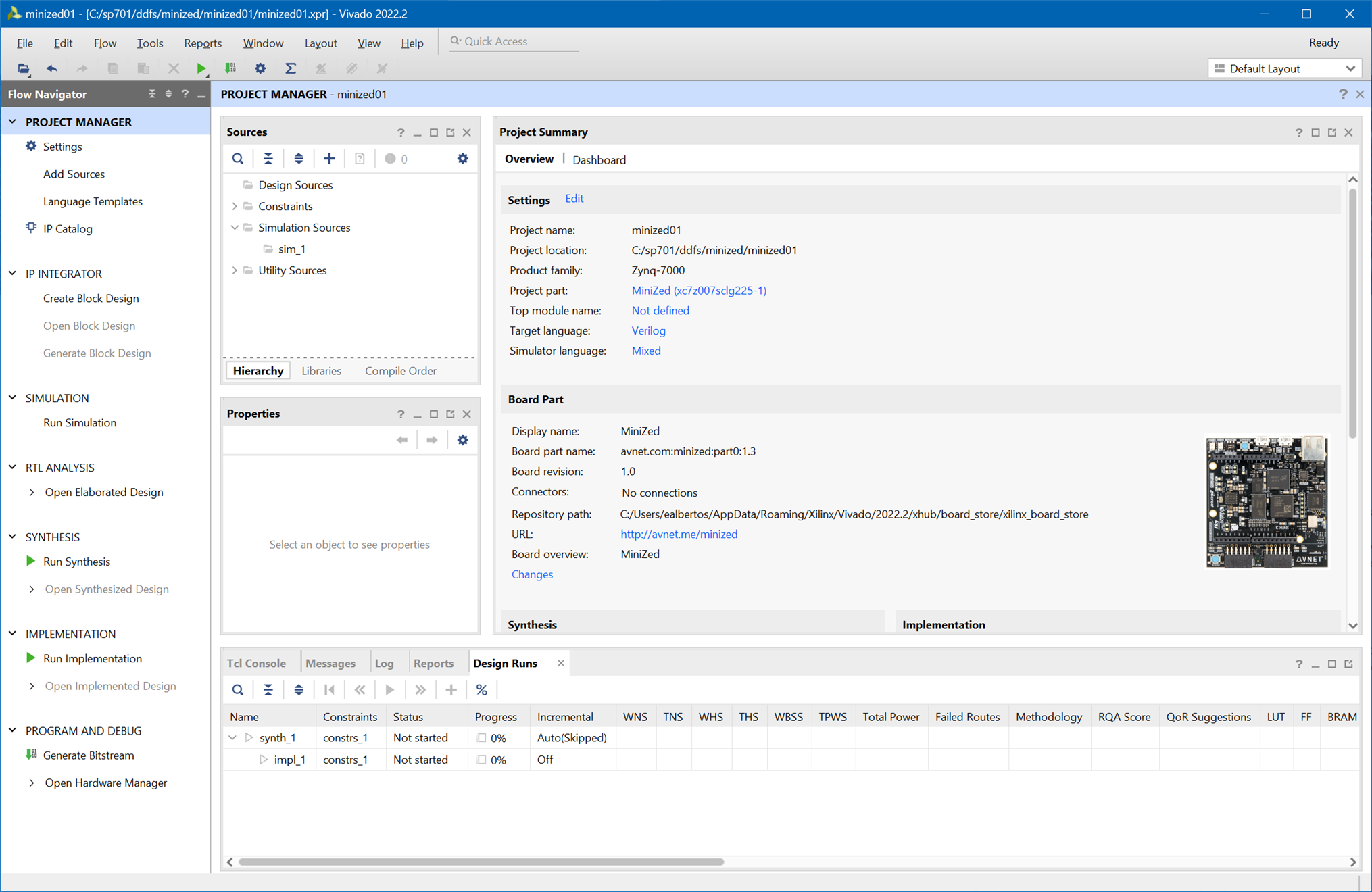
You can access to the hardware manager for programming the device
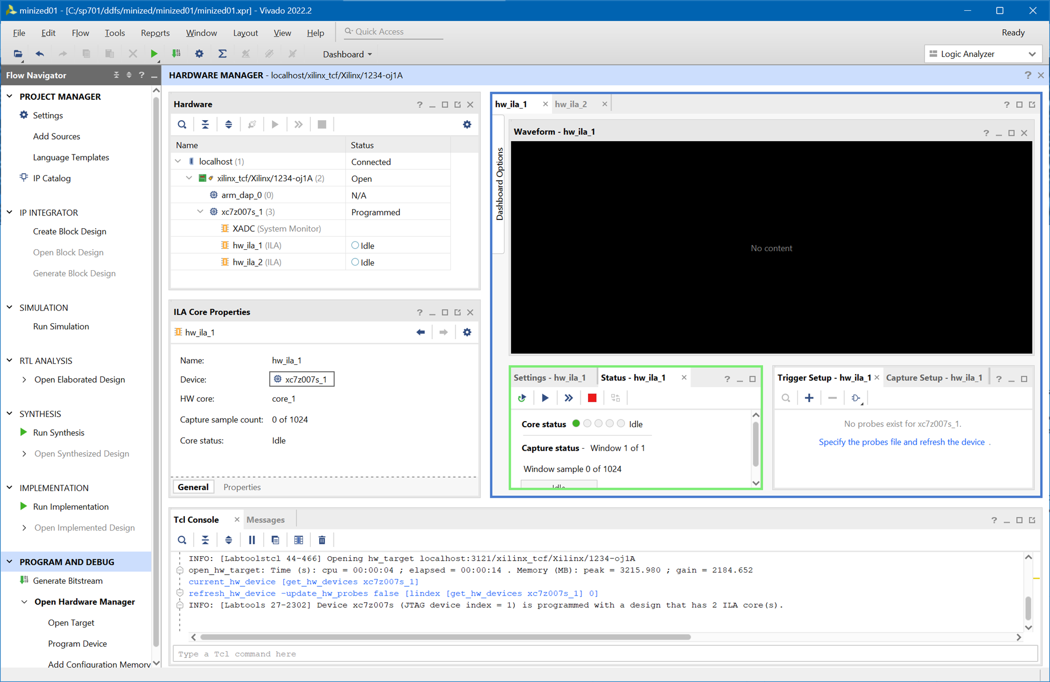
start_gui
xhub::refresh_catalog [xhub::get_xstores xilinx_board_store]
xhub::refresh_catalog: Time (s): cpu = 00:00:01 ; elapsed = 00:00:52 . Memory (MB): peak = 1004.070 ; gain = 0.000
set_param board.repoPaths {C:/Users/ealbertos/AppData/Roaming/Xilinx/Vivado/2022.2/xhub/board_store/xilinx_board_store C:/Users/ealbertos/AppData/Roaming/Xilinx/Vivado/2021.1/xhub/board_store/xilinx_board_store}
xhub::install [xhub::get_xitems avnet.com:xilinx_board_store:minized:1.3]
INFO: [xhubtcl 76-32] Installing object 'avnet.com:xilinx_board_store:minized:1.3' ...
INFO: [Common 17-1570] Installing object avnet.com:xilinx_board_store:minized:1.3 from remote host https://github.com/Xilinx/XilinxBoardStore.git
INFO: [Common 17-1573] Object avnet.com:xilinx_board_store:minized:1.3 has been installed successfully.
xhub::install: Time (s): cpu = 00:00:00 ; elapsed = 00:00:06 . Memory (MB): peak = 1004.070 ; gain = 0.000
create_project minized01 C:/sp701/ddfs/minized/minized01 -part xc7z007sclg225-1
INFO: [IP_Flow 19-234] Refreshing IP repositories
INFO: [IP_Flow 19-1704] No user IP repositories specified
INFO: [IP_Flow 19-2313] Loaded Vivado IP repository 'C:/Xilinx/Vivado/2022.2/data/ip'.
create_project: Time (s): cpu = 00:00:03 ; elapsed = 00:00:07 . Memory (MB): peak = 1010.566 ; gain = 6.496
set_property board_part avnet.com:minized:part0:1.3 [current_project]
WARNING: [Board 49-151] The current board 'avnet.com::minized:1.3' is from a local repo. The vivado install has a corresponding board with version greater than or equal to the local repo board. Please use boards from vivado install to avoid any upgrade/migrate issues
open_hw_manager
connect_hw_server -allow_non_jtag
INFO: [Labtools 27-2285] Connecting to hw_server url TCP:localhost:3121
INFO: [Labtools 27-2222] Launching hw_server...
INFO: [Labtools 27-2221] Launch Output:

****** Xilinx hw_server v2022.2
  **** Build date : Oct 14 2022 at 05:18:10
    ** Copyright 1986-2022 Xilinx, Inc. All Rights Reserved.


INFO: [Labtools 27-3415] Connecting to cs_server url TCP:localhost:0
INFO: [Labtools 27-3417] Launching cs_server...
INFO: [Labtools 27-2221] Launch Output:


******** Xilinx cs_server v2022.2.0
  ****** Build date   : Oct 05 2022-01:25:37
    **** Build number : 2022.2.1664925937
      ** Copyright 2017-2023 Xilinx, Inc. All Rights Reserved.


connect_hw_server: Time (s): cpu = 00:00:01 ; elapsed = 00:00:09 . Memory (MB): peak = 1031.328 ; gain = 6.383
open_hw_target
INFO: [Labtoolstcl 44-466] Opening hw_target localhost:3121/xilinx_tcf/Xilinx/1234-oj1A
open_hw_target: Time (s): cpu = 00:00:04 ; elapsed = 00:00:14 . Memory (MB): peak = 3215.980 ; gain = 2184.652
current_hw_device [get_hw_devices xc7z007s_1]
refresh_hw_device -update_hw_probes false [lindex [get_hw_devices xc7z007s_1] 0]
INFO: [Labtools 27-2302] Device xc7z007s (JTAG device index = 1) is programmed with a design that has 2 ILA core(s).
refresh_hw_sysmon  [get_hw_sysmons localhost:3121/xilinx_tcf/Xilinx/1234-oj1A/xc7z007s_1/SYSMON]
refresh_hw_device [lindex [get_hw_devices arm_dap_0] 0]
ERROR: [Labtoolstcl 44-513] HW Target shutdown. Closing target: localhost:3121/xilinx_tcf/Xilinx/1234-oj1A
Clocked Blinky Version
Now to finalize a version of the Blinky circuit using a PL fabric clock configured to 100 MHz
After the shock of not finding a clock for my LED blinking demo due to my lack of knowledge of Zynq architecture we are going to end up with a standalone version of led blinking using one of the clocks for the programmed logic configured from the ZYNQ7 Processing System Vivado IP Block Designer.
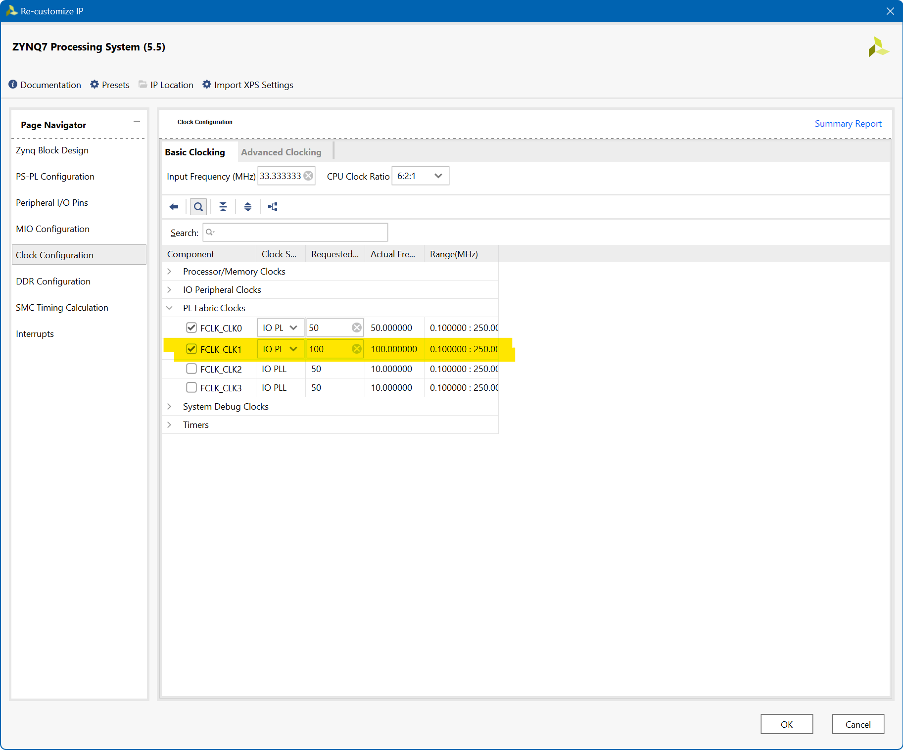
We create a 26-bit counter, in this case in Verilog since Vivado's IP Integrator block designer does not support modules in SystemVerilog.
When bit 24 is asserted, the green element of the bi-element LED turns on.
When bit 26 is asserted, the red element of the bi-element LED turns on.
`timescale 1ns / 1ps

module verilog_clocked_blinky(

    input  clk,
    output  led_g,
    output  led_r

    );

// reg for counter
reg [25:0] count = 0;

assign led_g = count[23];
assign led_r = count[25];

always @ (posedge(clk)) count <= count + 1;

endmodule
We assign the clock signal from the IP Integrator block designer.
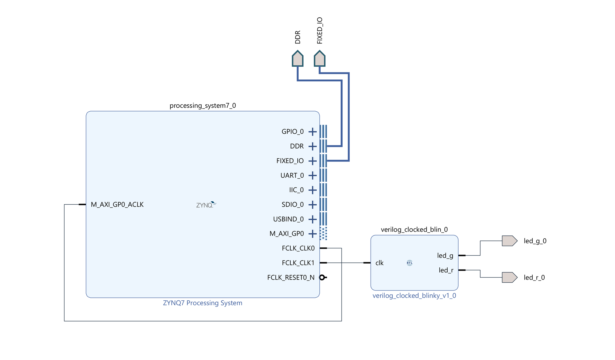
Constraints file
set_property PACKAGE_PIN E13 [get_ports led_g_0]
set_property IOSTANDARD LVCMOS33 [get_ports led_g_0]


set_property PACKAGE_PIN E12 [get_ports led_r_0]
set_property IOSTANDARD LVCMOS33 [get_ports led_r_0]
Here is the result. The bi-element LED lights following the sequence.
Summary
This has been my first blog and my first contact with the Path to Programmable III training sessions and the development kit provided by AMD and element14. It is being a path full of new discoveries of things that I did not know before or that I did without fully understanding them. I hope you found this account of my first steps with the Zynq interesting.
The next step will be to try to migrate a design made for the Microblaze softprocessor to the Zynq architecture. It will be difficult?
References
- Minized Technical Documents: MiniZed - Boards - Avnet Boards Community
- My participation in the: 7 Ways to Leave Your Spartan-6 FPGA
- My participation in; AMD SP701 - Experimenting with Sensor Fusion Design Challenge
- ds190-Zynq-7000-Overview.pdf
- ds187-XC7Z010-XC7Z020-Data-Sheet.pdf
Path to Programmable III Training Blog Series
- BLOG 1: P2P3 Getting Started. Clockless Hardware Blinky on the Avnet Minized
- BLOG 2: P2P3 AMD Vitis portability and reuse. Migrating a Microblaze bare metal environmental monitor App to the Zynq architecture.
- BLOG 3: P2P3 AMD Zynq-7000 SoC XADC. External Multiplexer Mode.
- BLOG 4: P2P3 AMD Vivado Cascaded Integrator Comb (CIC) Compiler. PDM Microphone to PCM Decimation
- BLOG 5: P2P3 Wireless sensors on the Avnet Minized. Getting Started with PetaLinux
- FINAL PROJECT: AMD Zynq SoC MIDI Vintage Sound Synthesizer - Final


Top Comments
-

navadeepganeshu
-
Cancel
-
Vote Up
+1
Vote Down
-
-
Sign in to reply
-
More
-
Cancel
Comment-

navadeepganeshu
-
Cancel
-
Vote Up
+1
Vote Down
-
-
Sign in to reply
-
More
-
Cancel
Children