Table of Contents
Introduction
Following the Path to Programmable series has been an interesting activity and the last couple of months were filled with excitement, channels and rush with a lot of new learnings. Nevertheless, like any journey through roadtest or project14 contest, this has been a fruitful experience and for me especially has opened up a whole new domain and possibilities to keep exploring forever in the times to come.
Through this blog, I am writing about my final project of building a flight simulator(or a type of that thing) interface utilising the sensors and peripherals of the MiniZed board. I like to technically call it a 'cute board' that encompasses a rich set of features(of course! with Zynq7000). In the previous blog, we've seen about interfacing a TFT LCD display and getting the sensor data streamed out. This project will be an extension of that - with a detailed explanation and expansion on the Vivado side which I had cut short in the earlier learning series. Right into it!
The Design Flow
This project involves using three different platforms and the development starts with the Vivado block design where the peripheral interfaces required are defined and mapped with the IPs within the PS section of the Zynq 7000. Here, the UART, I2C, and Quad SPI are used as serial interfaces.
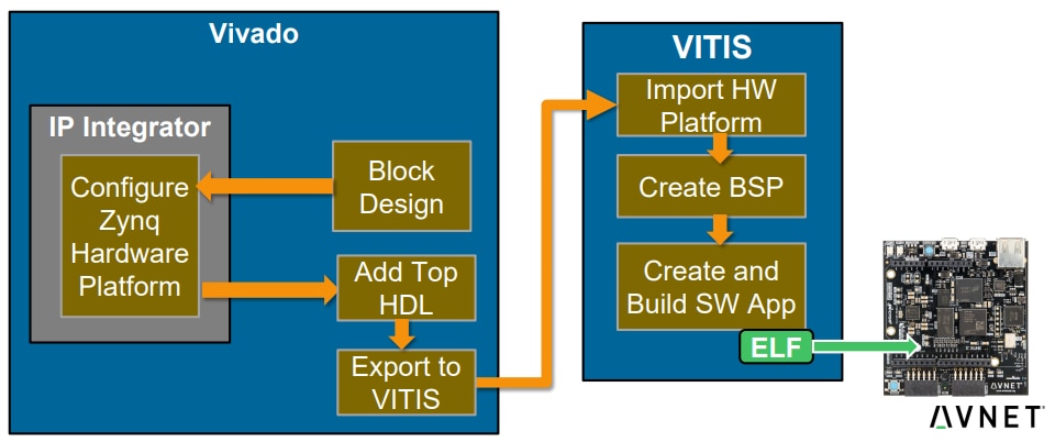
Next comes the software platform where these peripherals are instantiated and operations are performed to read and write data with them. This primarily happens in the ARM core within Zynq which boots up via the FSBL. First Stage Bootloader (FSBL) for Zynq configures the FPGA with hardware bitstream and loads the Operating System Image or Standalone Image(in our case standalone_domain) from the non-volatile memory (NAND/SD/eMMC/QSPI) to Memory (DDR/TCM/OCM) and takes the A9 out of reset. The project application then runs on top of this just like any microcontroller and links with the hardware peripherals through memory-mapped system bus master AXI.
- Creating a new Vivado project
- Creating a block design with Zynq
- Adding peripheral IPs(Pmod_NAV, axi_gpio, axi_quad_spi, axi_iic)
- Running the synthesis process
- Preparing a constraints file(with Minized board constraints file reference) to map the IP block I/Os to the FPGA I/O pins.
- Generating bitstream(.bit) file directly
- Exporting the Vivado platform file(.xpr) to the Vitis software development platform
- Importing the platform in Vitis and creating a new application project on top of this platform
- Writing application code and running the system
- Exchanging the data through serial with the computer running Processing IDE and running the application code
Blocks and Interfaces
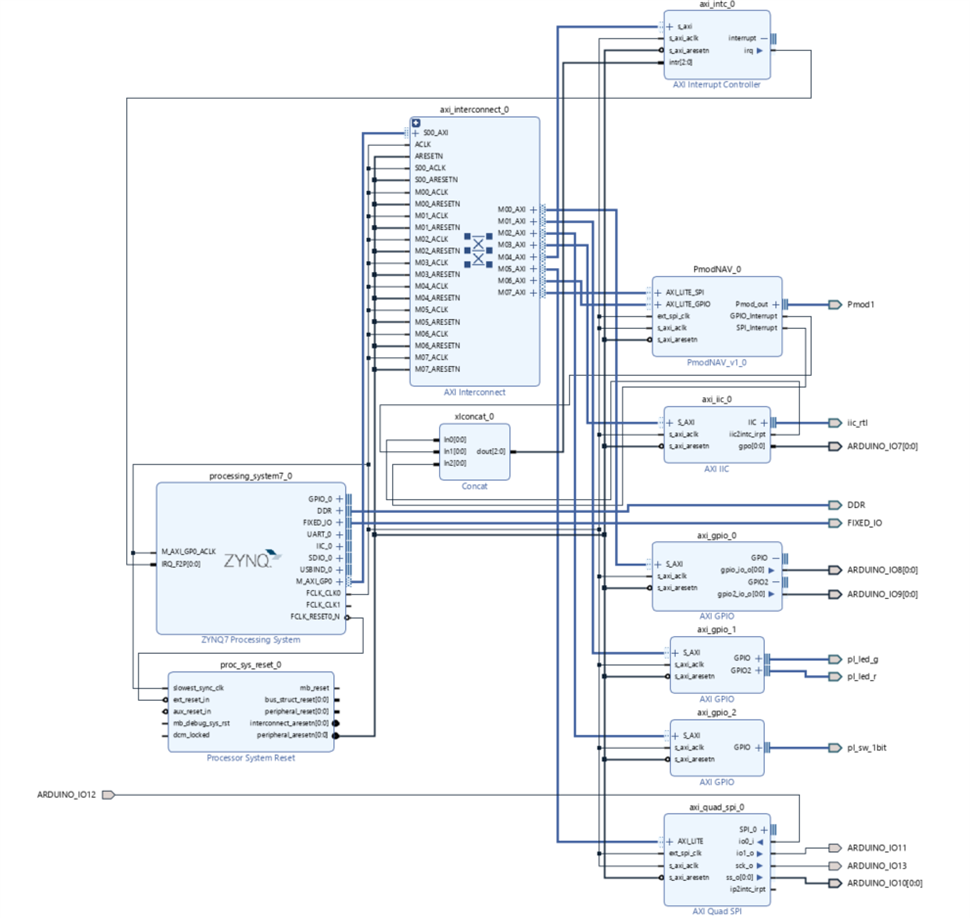
After creating the new project in Vivado, here comes the first step. I have a couple of sensors to be interfaced and a 1.8-inch TFT display. Thinking about the blocks required, we need the Zynq PS(the whole processing system block), AXI Interconnect(to link PS to PL) and multiple interface blocks like Pmod_NAV, axi_gpio, axi_quad_spi, axi_iic for LEDs, Pmod, I2C sensor and SPI based TFT display. For I2C, SPI, UART etc., we have an option to use either the PS existing serial interfaces or the axi_'x' IP blocks on the PL.
Selecting the Zynq Peripherals
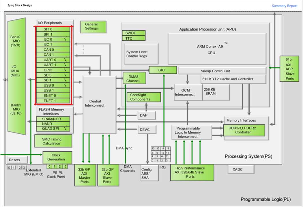
The Vivado block designer allows to interactively edit the IP blocks and the above noted peripherals are ticked to be added to the design. The IO map allows to allotting the peripherals to different MIO pins with different combinations and a detailed report is generated.

Adding Pmod IPs
By default, the peripheral module IPs are not included in the Vivado and are supplied by manufacturers like Avnet and Digilent. External IPs can be imported through these simple steps: Using Digilent Pmod IPs in Vivado and Vitis - Digilent Reference.
Digilent's Pmod IPs are available at vivado-library/ip/Pmods at master · Digilent/vivado-library (github.com)
Building the Design and Address Mapping

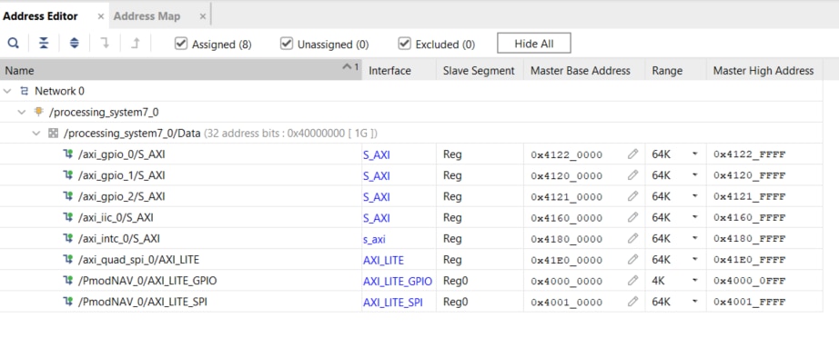
The addresses can be viewed in the address editor window available in the design tab and modifications can be done here in case.
One I2C, SPI and GPIO ports go to the Arduino header in the MiniZed for HTU21, TFT and LED interfaces. The Pmod NAV IP itself holds SPI and the output bus is mapped to the Pmod1 header.
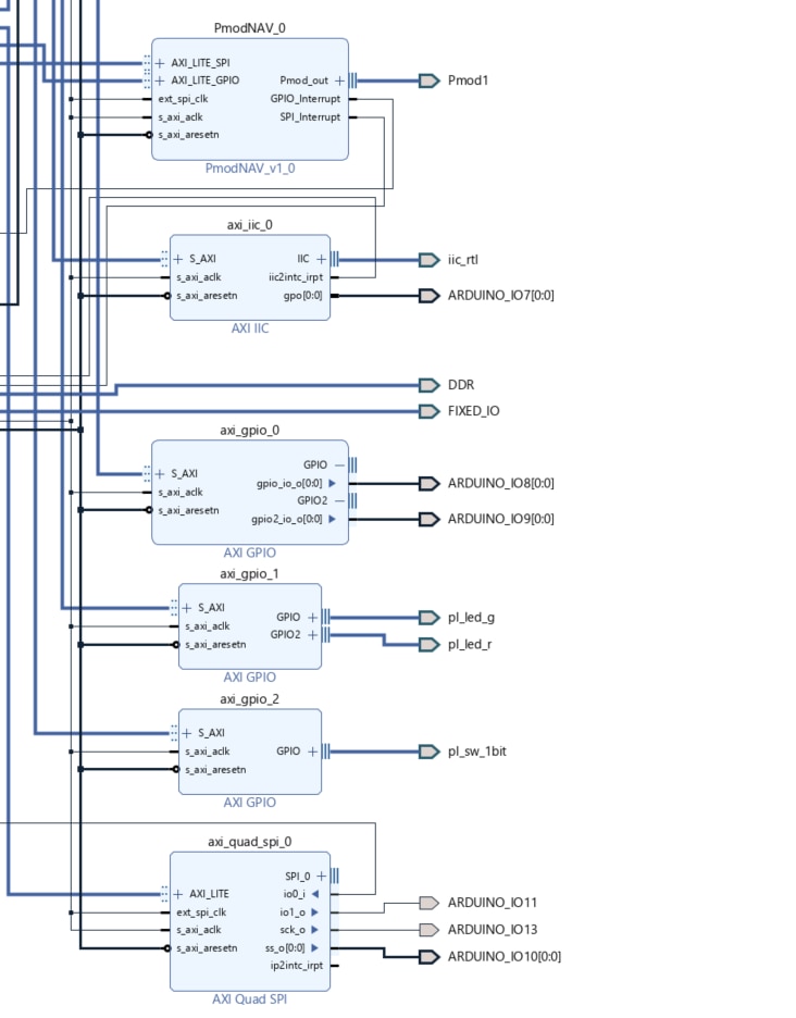
The internal settings of GPIO and Quad SPI IPs:
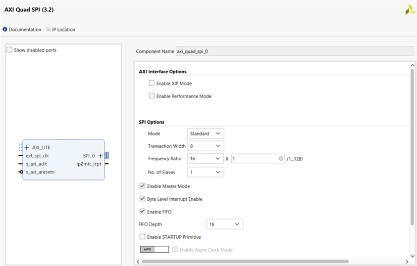
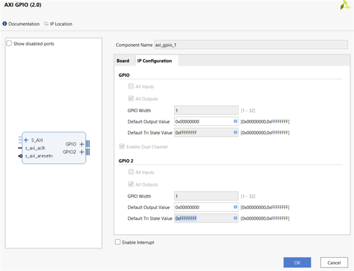
Hardware Implementation
Design Synthesis
The next phase is to synthesize the design and run the implementation. Synthesis is the process of transforming an RTL-specified design into a gate-level representation. Vivado synthesis is timing-driven and optimized for memory usage and performance(more info ug901-vivado-synthesis.pdf • Viewer • AMD Adaptive Computing Documentation Portal (xilinx.com)) and the layout looks something like this after synthesis. Hardly, any PL is used in this design and so a lot of empty real estate. The below image highlights the Pmod1 pins used for the PmodNAV in this design:

Adding Pin Constraints and Modifying IO Levels
This step seems a bit confusing, but nothing is to be created from scratch. Based on the board selected during the project creation and the IPs added, as soon as you open the synthesized design and go to the I//O ports, a tabular window shows up where all the ports are shown, assigned directions and we need to then select the right I/O standard(example: LVCMOS33) and the package pin.

With respect to the chosen board, the peripheral mappings can be seen and used to choose the pins. The MiniZed pin constraint file is given here hdl/Boards/MINIZED/minized_pins.xdc at master · Avnet/hdl (github.com) and this is what I had to customise and enter for project-specific configuration(.xdc):
The Final Constraints File
set_property IOSTANDARD LVCMOS33 [get_ports {ARDUINO_IO9[0]}]
set_property IOSTANDARD LVCMOS33 [get_ports {ARDUINO_IO8[0]}]
set_property IOSTANDARD LVCMOS33 [get_ports iic_rtl_scl_io]
set_property IOSTANDARD LVCMOS33 [get_ports iic_rtl_sda_io]
set_property IOSTANDARD LVCMOS33 [get_ports Pmod1_pin1_io]
set_property IOSTANDARD LVCMOS33 [get_ports Pmod1_pin2_io]
set_property IOSTANDARD LVCMOS33 [get_ports Pmod1_pin3_io]
set_property IOSTANDARD LVCMOS33 [get_ports Pmod1_pin4_io]
set_property IOSTANDARD LVCMOS33 [get_ports Pmod1_pin7_io]
set_property IOSTANDARD LVCMOS33 [get_ports Pmod1_pin8_io]
set_property IOSTANDARD LVCMOS33 [get_ports Pmod1_pin9_io]
set_property IOSTANDARD LVCMOS33 [get_ports Pmod1_pin10_io]
set_property IOSTANDARD LVCMOS33 [get_ports {ARDUINO_IO10[0]}]
set_property IOSTANDARD LVCMOS33 [get_ports ARDUINO_IO11]
set_property IOSTANDARD LVCMOS33 [get_ports ARDUINO_IO12]
set_property IOSTANDARD LVCMOS33 [get_ports ARDUINO_IO13]
set_property IOSTANDARD LVCMOS33 [get_ports {ARDUINO_IO7[0]}]
set_property PACKAGE_PIN L15 [get_ports Pmod1_pin1_io]
set_property PACKAGE_PIN M15 [get_ports Pmod1_pin2_io]
set_property PACKAGE_PIN L14 [get_ports Pmod1_pin3_io]
set_property PACKAGE_PIN M14 [get_ports Pmod1_pin4_io]
set_property PACKAGE_PIN K13 [get_ports Pmod1_pin7_io]
set_property PACKAGE_PIN L13 [get_ports Pmod1_pin8_io]
set_property PACKAGE_PIN N13 [get_ports Pmod1_pin9_io]
set_property PACKAGE_PIN N14 [get_ports Pmod1_pin10_io]
set_property PACKAGE_PIN M10 [get_ports {ARDUINO_IO10[0]}]
set_property PACKAGE_PIN M11 [get_ports ARDUINO_IO11]
set_property PACKAGE_PIN R11 [get_ports ARDUINO_IO12]
set_property PACKAGE_PIN P11 [get_ports ARDUINO_IO13]
set_property PACKAGE_PIN N8 [get_ports {ARDUINO_IO7[0]}]
set_property PACKAGE_PIN G15 [get_ports iic_rtl_scl_io]
set_property PACKAGE_PIN F15 [get_ports iic_rtl_sda_io]
set_property PACKAGE_PIN M9 [get_ports {ARDUINO_IO8[0]}]
set_property PACKAGE_PIN N9 [get_ports {ARDUINO_IO9[0]}]

Vitis Implementation
In the earlier blog, we've seen Vitis development for interfacing TFT display and the flow would be the same here wherein a platform file is imported and an application project is built on top.
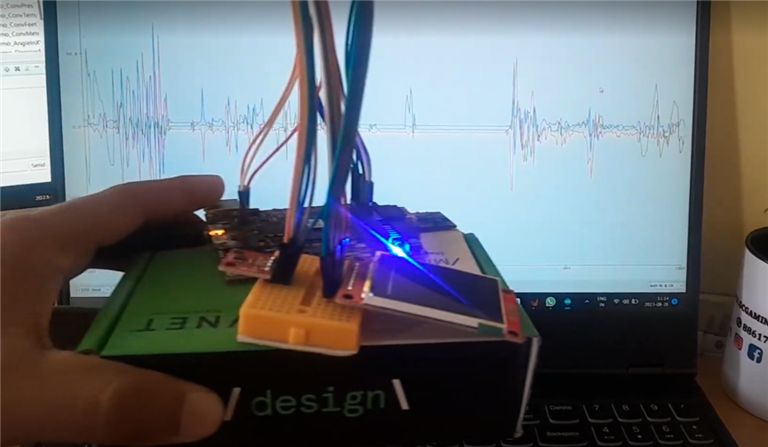
Primarily, PmodNAV is used here and it does give a lot of data with 10 DoF! Adding the Pmod library, here it is interfaced with the serial plotter for quick testing.Basic run with the accelerometer and gyroscope data plots:

/***************************** Include Files *******************************/

#include <stdio.h>
#include "math.h"
#include "PmodNAV.h"
#include "sleep.h"
#include "xil_cache.h"
#include "xparameters.h"
#include <stdio.h>
#include <sleep.h>
#include <time.h>
#include "platform.h"
#include "xil_printf.h"
#include "xparameters.h"
#include "xgpio.h"
#include "xstatus.h"
#include "delay/Delay.h"
#include "SPI.h"
#include "htu21d.h"
#include "lcd/LCD_Driver.h"
#include "lcd/LCD_GUI.h"
#include "htu21d.h"
/*************************** Global Variables ******************************/

PmodNAV nav;
char compassbuf[16] = {};
char acclbuf[32] = {};
char gyrobuf[32] = {};

/********************* Function Forward Declarations ***********************/

void NavDemo_Initialize(void);
void NavDemo_Run(void);
void NavDemo_Cleanup(void);

float NavDemo_ComputePref(float hPa, float altitudeMeters);
float NavDemo_ConvPresToAltF(float Pref, float hPa);
float NavDemo_ConvPresToAltM(float Pref, float hPa);

float NavDemo_ConvTempCToTempF(float tempC);
float NavDemo_ConvFeetToMeters(float feet);
float NavDemo_ConvMetersToFeet(float meters);

float NavDemo_AngleInXY(NAV_RectCoord r);
float NavDemo_DegreesFromVertical(NAV_RectCoord r);
float NavDemo_ScalarProjection(NAV_RectCoord orient, NAV_RectCoord r);

void NavDemo_EnableCaches(void);
void NavDemo_DisableCaches(void);

/***************************** Function Definitions ************************/

/*** void NavDemo_Initialize()
**
**   Parameters:
**      None
**
**   Return Values:
**      None
**
**   Errors:
**      None
**
**   Description:
**      This function initializes the hardware used in the demo and starts a
**      PmodNAV driver device
*/
void NavDemo_Initialize(void) {
    NavDemo_EnableCaches();
    NAV_begin ( // intialize the PmodNAV driver device
        &nav,
        XPAR_PMODNAV_0_AXI_LITE_GPIO_BASEADDR,
        XPAR_PMODNAV_0_AXI_LITE_SPI_BASEADDR
    );
    NAV_Init(&nav); // initialize the connection with each spi slave
}

/*** void NavDemo_Run(void)
**
**   Parameters:
**      None
**
**   Return Values:
**      None
**
**   Errors:
**      None
**
**  Description:
**      This function encapsulates the PmodNAV demo, capturing data from each
**      part on the PmodNAV and displaying it over a UART connection
*/
void NavDemo_Run(void) {
   float Pref,
         tempF,
         dps,
         magXYd,
         alt;
    char *compass[8] = {"North", "North-East", "East", "South-East", "South",
          "South-West", "West", "North-West"};
    char *str;

   NAV_ReadPressurehPa(&nav);
   alt = NavDemo_ConvFeetToMeters(3018); // altitude for Bengaluru, KA in feet
   Pref = NavDemo_ComputePref(nav.hPa, alt);
   usleep(100000);

   while(1){
      NAV_GetData(&nav);

      dps = NavDemo_ScalarProjection(nav.acclData, nav.gyroData);
      if (dps < -4) // Remove some noise around 0
         str = "Clockwise";
      else if (dps > 4)
        str = "Counter-Clockwise";
      else
         str = "Marginal";

      magXYd = NavDemo_AngleInXY(nav.magData);
      str = compass[(int)((magXYd + 22.5) / 45.0) % 8];
      tempF = NavDemo_ConvTempCToTempF(nav.tempC);

      printf("%.2f %.2f %.2f %.2f %.2f\n",nav.acclData.X,nav.gyroData.Y,nav.gyroData.Z,nav.tempC,nav.hPa);
    }
}

/*** void NavDemo_Cleanup(void)
**
**   Parameters:
**      None
**
**   Return Values:
**      None
**
**   Errors:
**      None
**
**   Description:
**      This function closes the PmodNAV device and ends the demo
*/
void NavDemo_Cleanup(void) {
   NAV_end(&nav);
   NavDemo_DisableCaches();
}

/*** float NavDemo_ComputePref(float hPa, float altitudeMeters)
**
**   Parameters:
**      hPa            - a reading of the current pressure
**      altitudeMeters - the parameter used to calibrate the altitude computing,
**                       is considered known for the wanted location
**
**   Return Values:
**      Pref - the reference pressure in hPa
**
**   Errors:
**      None
**
**   Description:
**      This function provides the reference pressure computed with a known
**      altitude for the given location it performs a pressure reading, then
**      computes the reference pressure using the altitude parameter.
**
**      It needs to be called once for the correct operation of the altitude
**      function, all the following pressure readings are affected by it. This
**      This is needed because the current altitude is also affected by the
**      current sea level air pressure, while the barometric pressure formula
**      used to compute altitude is considering the sea level pressure constant
**      at all times.
*/
float NavDemo_ComputePref(float hPa, float altitudeMeters) {
   float altitudeFeet = NavDemo_ConvMetersToFeet(altitudeMeters);
   float temp = 1 - (altitudeFeet / 145366.45);
   temp = hPa / (powf(temp, 1.0 / 0.190284));
   return temp;
}

/*** float NavDemo_ConvPresToAltM(float hPa)
**
**   Parameters:
**      float hPa - parameter representing the value of pressure in hPa
**
**   Return Values:
**      float altMeters - it returns the current altitude based on the measured
**                        pressure and the previously computed reference
**                        pressure
**
**   Errors:
**      None
**
**   Description:
**      This function calls the ConvPresToAltF function to obtain the altitude
**      in feet. Then it converts it to meters.
**      The Pref is computed once and used for further calculations of the
**      altitude.
*/
float NavDemo_ConvPresToAltM(float Pref, float hPa) {
   return NavDemo_ConvPresToAltF(Pref, hPa) * 0.3048;
}

/*** float NavDemo_ConvPresToAltF(float Pref, float hPa)
**
**   Parameters:
**      float Pref - pressure reference
**      float hPa  - parameter representing the value of pressure in hPa
**
**   Return Values:
**      float altFeet - returns the value of the altitude in feet
**
**   Errors:
**      None
**
**   Description:
**      This function converts the provided pressure to altitude (in feet) using
**      the previously computed Pref as reference pressure.
**
**      The calculation of altitude is based on the following formula:
**      Altitude_ft = (1-pow(*Pressure_mb/1013.25,0.190284))*145366.45
*/
float NavDemo_ConvPresToAltF(float Pref, float hPa) {
   return ((1 - pow(hPa / Pref, 0.190284)) * 145366.45);
}

/*** float NavDemo_ConvTempCToTempF(float tempC)
**
**   Parameters:
**      tempC - parameter representing the value of temperature expressed in
**              degrees Celsius
**
**   Return Values:
**      float - returns the value of the temperature in degrees Fahrenheit
**
**   Errors:
**      None
**
**   Description:
**      This function performs the conversion from Celsius to Fahrenheit degrees
**      and returns the value of temperature in F
**
*/
float NavDemo_ConvTempCToTempF(float tempC) {
   return 32 + (tempC * 1.8);
}

/*** float NavDemo_ConvFeetToMeters(float feet)
**
**   Parameters:
**      feet - a distance in feet
**
**   Return Values:
**      float - returns the parameter feet converted to meters
**
**   Errors:
**
**   Description:
**      This function performs the conversion from units of feet to meters
*/
float NavDemo_ConvFeetToMeters(float feet) {
   return feet * 0.3048;
}

/*** float NavDemo_ConvMetersToFeet(float meters)
**
**   Parameters:
**      meters - a distance in meters
**
**   Return Values:
**      float - returns the parameter meters converted to feet
**
**   Errors:
**
**   Description:
**      This function performs the conversion from units of meters to feet
*/
float NavDemo_ConvMetersToFeet(float meters) {
   return meters * 3.28084;
}

/*** float NavDemo_AngleInXY(NAV_RectCoord r)
**
**   Parameters:
**      r - the vector in rectangular coordinates to be converted to polar
**
**   Return Value:
**      p - returns the polar coordinate representation of the vector r
**          projected onto the XY plane
**
**   Errors:
**      None
**
**   Description:
**      The function computes the degrees the vector r is rotated about the
**      Z-axis from the vector (X=1,0,0)
*/
float NavDemo_AngleInXY(NAV_RectCoord r) {
   float d;
   if (r.X == 0)
      d = (r.Y < 0) ? 90 : 0;
   else
      d = atan2f(r.Y, r.X) * 180 / M_PI;
   if (d > 360)
      d -= 360;
   else if (d < 0)
      d += 360;
   return d;
}

/*** float NavDemo_DegreesFromVertical(NAV_RectCoord r)
**
**   Parameters:
**      r - the xyz vector to be operated upon
**
**   Return Value:
**      float - the angle in degrees between the vector r and the unit Z vector.
**
**   Errors:
**      None
**
**  Description:
**      The function computes the angle in degrees between the vector r and the
**      vector (0,0,Z=1)
*/
float NavDemo_DegreesFromVertical(NAV_RectCoord r) {
   // Determine the magnitude of the vector r.
   float rM = sqrtf(powf(r.X, 2) + powf(r.Y, 2) + powf(r.Z, 2));
   if (rM == 0)
      return 0.0;
   return acosf(r.Z / rM) * (180.0 / M_PI);
}

/*** float NavDemo_ScalarProjection(NAV_RectCoord orient, NAV_RectCoord r)
**
**   Parameters:
**      orient   - the xyz vector
**      rotation - the xyz vector
**
**   Return Value:
**      float - the angle in degrees between the vector r and the unit Z vector.
**
**   Errors:
**      None
**
**   Description:
**      This function returns the scalar projection of the r vector onto the
**      orient vector. This can be used with gyroscope and accelerometer data to
**      determine rotation of the PmodNAV about true vertical.
*/
float NavDemo_ScalarProjection(NAV_RectCoord orient, NAV_RectCoord r) {
   float oM = sqrtf(powf(orient.X, 2) + powf(orient.Y, 2) + powf(orient.Z, 2));
   return (r.X * orient.X + r.Y * orient.Y + r.Z * orient.Z) / oM;
}
With TFT Interface
/*
* Program for multi-sensor interface and display on 1.8 inch TFT with MiniZed
* using the PL defined Pmod, GPIO and SPI IP blocks
* More details and full source file at https://github.com/NavadeepGaneshU/Path-to-Programmable-III_MiniZed
*
* TFT | MiniZed
* --------------
* Vcc | 5V
* GND | GND
* CS | IO_10
* RESET| IO_8
* A0 | IO_9
* SDA | IO_11
* SCK | IO_13
* LED | 3.3V
*
* HTU21D pin maps to SDA and SCL of the MiniZed arduino header pins
* Pmod NAV at Pmod 1
*
*/

/***************** Includes *****************/
#include <stdio.h>
#include <sleep.h>
#include <time.h>
#include "platform.h"
#include "xil_printf.h"
#include "xparameters.h"
#include "xgpio.h"
#include "xstatus.h"
#include "delay/Delay.h"
#include "SPI.h"
#include "htu21d.h"
#include "lcd/LCD_Driver.h"
#include "lcd/LCD_GUI.h"
#include "htu21d.h"

/***************** User Definitions *****************/
#define BACKGROUND WHITE
#define FOREGROUND BLUE
#define DELAY 1000

/***************** User Peripheral Instances *****************/
extern XGpio gpio1;
extern XSpi SpiInstance;
extern const unsigned char font[] ;

void htu21d_main_menu(void);

int main()
{
int Status;
float temperature;
float relative_humidity;

htu21d_status stat;

char tempbuf[16] = {};
char humibuf[16] = {};

init_platform(); //Initialize the UART

/* Initialize the GPIO driver */
Status = XGpio_Initialize(&gpio1, XPAR_AXI_GPIO_0_DEVICE_ID);
if (Status != XST_SUCCESS) {
xil_printf("GPIO Initialization Failed!\r\n");
return XST_FAILURE;
}

/* Set up the AXI SPI Controller */
Status = XSpi_Init(&SpiInstance,SPI_DEVICE_ID);
if (Status != XST_SUCCESS) {
xil_printf("SPI Initialization Failed!\r\n");
return XST_FAILURE;
}

/* Set the AXI address of the IIC core */
htu21d_init(XPAR_AXI_IIC_0_BASEADDR);

/* TFT LCD initialization */
LCD_SCAN_DIR LCD_ScanDir = SCAN_DIR_DFT; //SCAN_DIR_DFT = D2U_L2R
LCD_Init(LCD_ScanDir );

stat = htu21d_set_resolution(htu21d_resolution_t_14b_rh_12b); // Set resolution to 12-bit RH and 14-bit Temp

while(1)
{
stat = htu21d_read_temperature_and_relative_humidity(&temperature, &relative_humidity);
if(stat==htu21d_status_ok){
}else if(stat==htu21d_status_i2c_transfer_error){
printf("Transfer Error.");
}else if(stat==htu21d_status_crc_error){
printf("CRC Error.");
}

LCD_Clear(GUI_BACKGROUND);

NavDemo_Initialize();
NavDemo_Run();
NavDemo_Cleanup();
}
return 0;
}
Using Processing IDE
Processing4.0 is an open-source graphical and visual development environment where the interfaces can be built through processing code and taking external data for activities. Say for example one has to build a gauge indicating some value. Then, processing has a solution using:
  // 1. Redaing from serial port
  port = new Serial(this, "COM10", 115200);
  if (port.available() > 0) {
    String val = port.readString();
    list = split(val, ' ');
    float humidity = float(list[0]);
    }

  // 2. A meter for displaying Humidity value
  int mx = m.getMeterX();
  int my = m.getMeterY();
  int mw = m.getMeterWidth();

  m2 = new Meter(this, mx + mw + 20, my);
  m2.setMeterWidth(400);
  m2.setTitleFontSize(20);
  m2.setTitleFontName("Arial bold");
  m2.setTitle("Humidity (%)");
  m2.setDisplayDigitalMeterValue(true);

  String[] scaleLabelsH = {"0", "10", "20", "30", "40", "50", "60", "70", "80", "90", "100"};
  m2.setScaleLabels(scaleLabelsH);
  m2.setScaleFontSize(18);
  m2.setScaleFontName("Times New Roman bold");
  m2.setScaleFontColor(color(200, 30, 70));

  m2.setArcColor(color(141, 113, 178));
  m2.setArcThickness(10);
  m2.setMaxScaleValue(100);

  m2.setNeedleThickness(3);

  m2.setMinInputSignal(0);
  m2.setMaxInputSignal(100);

  //3. Update the values to the meter read through the serial port
  m.updateMeter(int(humidity));
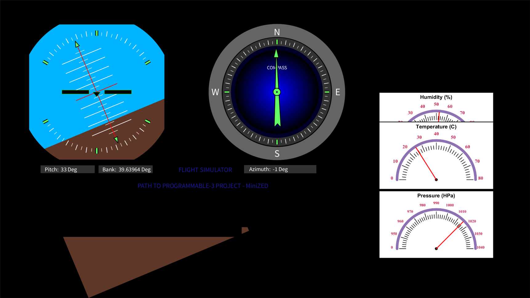
This way, the flight simulator interface is generated and linked with the accelerometer and gyroscope sensor data along with temperature, humidity and pressure. Full code is in the linked GitHub repo.


Demo Clips and Video
In the display, the left side meter is the altitude indicator or the gyro/altitude horizon indicator. The X data is taken from the Accelerometer, Y and Z from the gyro. The azimuth compass indicates the instantaneous direction that the craft is taking. If there is no instantaneous change in the direction, it settles down at N indicating that it's the current heading. The idea was to make something like this Primary flight display - Wikipedia


 _
_
_
I literally spent a lot of time hanging around this and there is some fun involved when you play with something you know how is it built. Other games don't impress me now anymore :)
Do share some hints if you have an idea how this can be extended or add some more touches to make it yet more exiting...
Code and Resources
Also Read: #PathtoProgrammable3 training blogs
Path to Programmable III: MiniZed - not so mini with its capabilities!
Path to Programmable III with MiniZed - Platforms, PWM Module and LED: A perfectly no sense app
Path to Programmable III with MiniZed: 1G ENET, GTX, NEON - what is it unique that FPGAs do at all?

.png-1440x400x2.png?sv=2016-05-31&sr=b&sig=UOjRrt8WfAAAFF0jvxsbeYvr5Czq6PliI8tFXnt%2FciI%3D&se=2026-01-23T23%3A59%3A59Z&sp=r&_=hik3WZDRrjJhKPfa/xOg1g==)