


The goal - have a range hood which is cooler than yours 
See blog post #1 for links to all the posts.
In this installment, I cover hooking up basically all the electronic components. I also start to get into some of the software work that I've done so far in Node Red. I won't get into much detail about the code in this post since it is more focused on hooking up the components & basic communication. Towards the end I also start integrating to the Home Automation server in OpenHAB via MQTT. This will provide a mobile user interface and allow external data to link in to the range hood - such as applying presence detection to flag if the stove is left on when we leave the house.
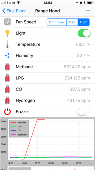
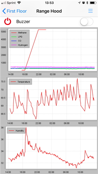
The user interface mockups I posted in the first blog are done through the OpenHAB HabPanel. I don't think I will use this on the final project since it would require an active connection to the home automation server. Instead, I think I will use the Node Red Dashboard add-on. It can provide buttons, display images and graphs. This should do all the things I need. Some of the info in this post was mentioned earlier, but the focus of this post is implementation versus planning. There was a lot of supporting circuitry to get the four analog sensors to read into the Pi, and I'll likely have one more follow up later on.
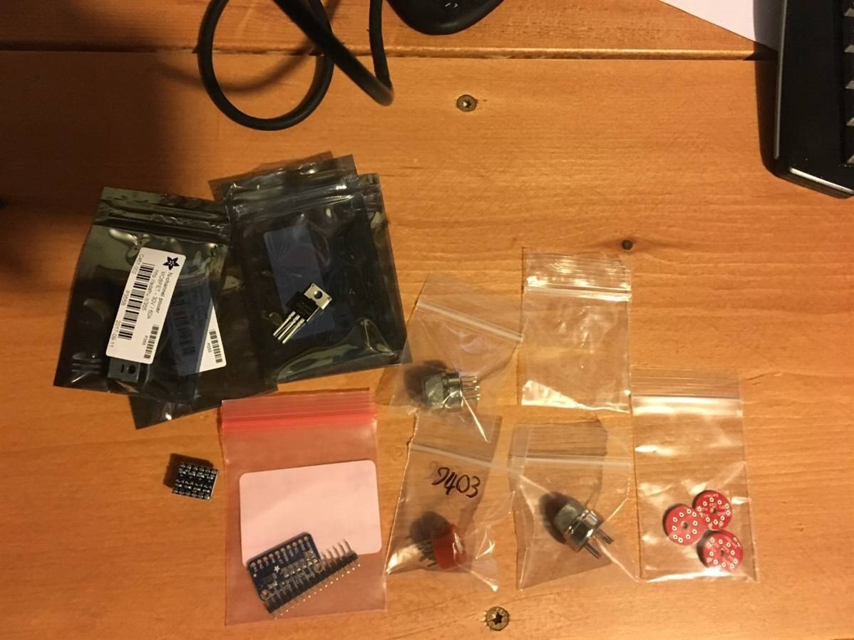
Electrical components:
4x "MQ" air quality sensors (see blog post #5)
4x N-Channel mosfets to run the heater circuits for said sensors
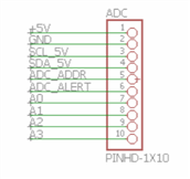
1x Analog to digital converter; I2C
1x Pi Camera
1x relay board with 4 channels
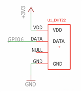
1x DHT22 temperature/humidity sensor
1x bi-directional level shifter (bridge I2C bus between 3.3V and 5V)
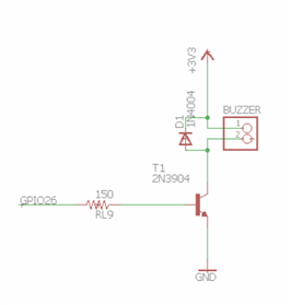
1x radio shack buzzer (use case still to be defined; but I had one laying around, so why not?)
1x 4D Systems 2.4" touchscreen (See blog post #3 to see some of the problems that I still have to work out with this)
There was also some supporting circuitry for these items - various resistors, transistors, diodes, LEDs and so on.
The first step was getting the breadboard populated. This was like a little game of Tetris trying to get everything to fit. I will be using both 3.3V and 5V components, so one rail on the breadboard was used for each. The Analog to Digital converter is running on the 5V rail to read the MQ sensors. It talks over I2C to the RaspberryPi over the bi-directional level shifter.
This is the end result -
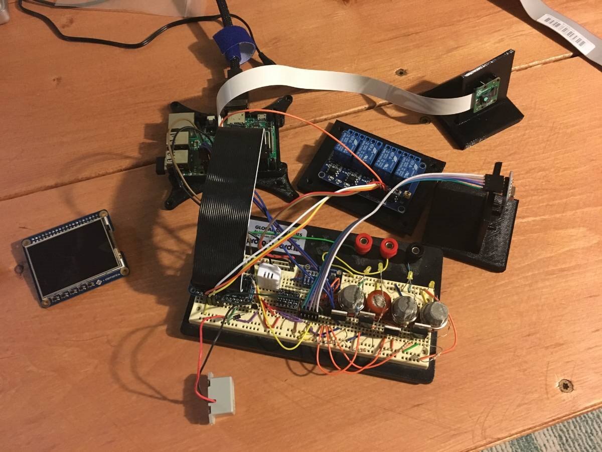
The breadboard is obviously the large bit in the middle of the photo. Top right is the Raspberry Pi Camera. The four blue cubes near it are the fan/light relays. On the right side is the thermal camera. The grey box near the bottom is the buzzer. I have the 4D touchscreen on the left.
Here is detail of the breadboard -
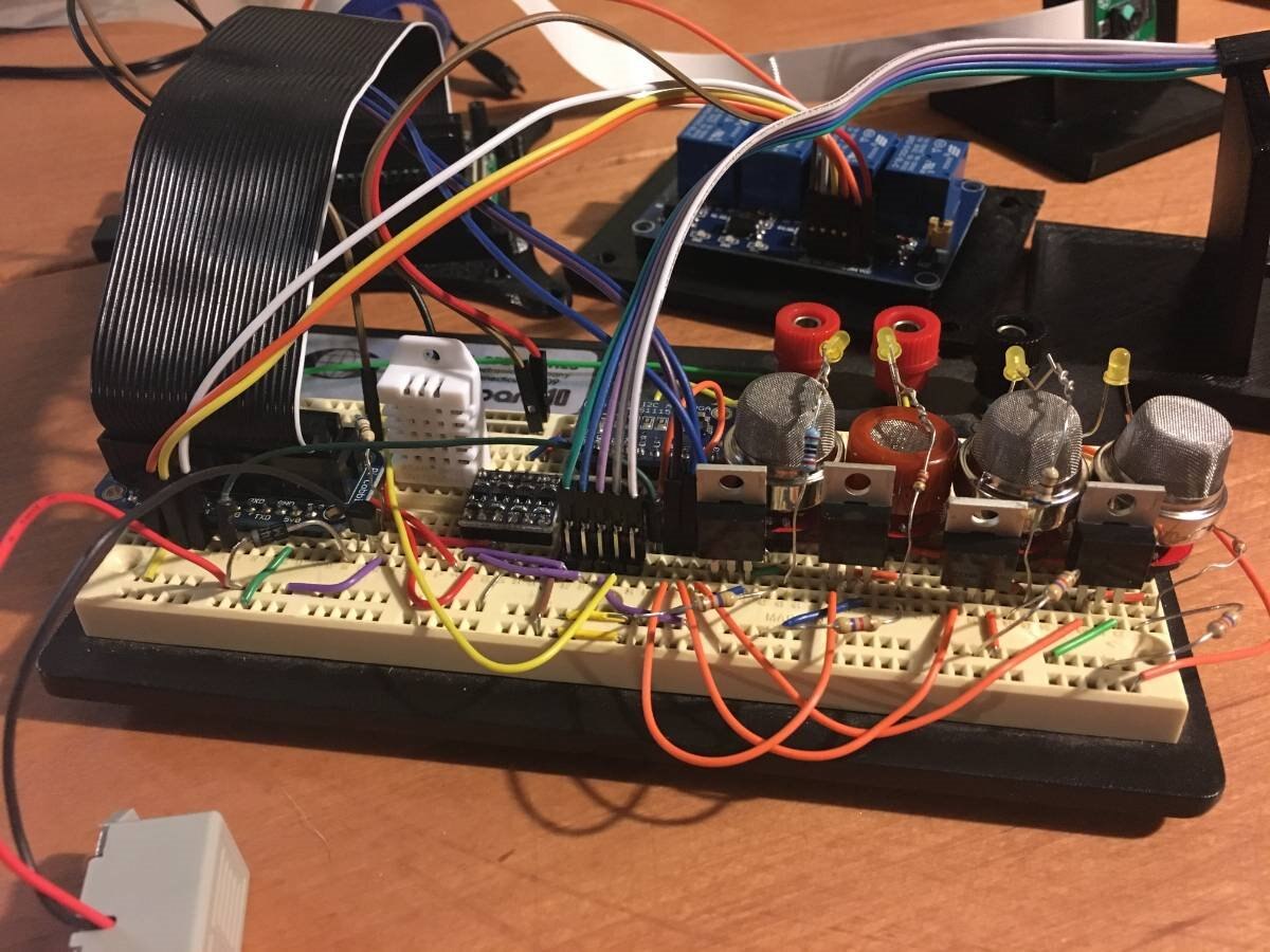
On the right you can see the four MQ sensors with N-Channel mosfets in front of them. I have yellow LEDs up above to show the heater is running. To the left of that the cable comes in and lands for thermal camera. The ADC chip is slightly obscured from view on the far side of the board. The level shifter is just to the left of that. The white block is the DHT Temperature/Humidity sensor. Pretty crowded!
Wiring connections:
I started by soldering the four MQ sensors on little breakout boards. I found these on Sparkfun and they make the sensor more breadboard friendly. I placed them at one end of the board and placed my Pi Cobbler at the other end; then worked towards the middle.
The ADC went on one side and the level shifter straddled the middle.
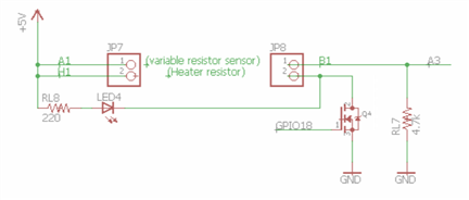
I put the DHT at the end towards the Pi Cobbler and had just enough room to get a NPN on the board to trigger the buzzer.
The buzzer circuit also required a 150 Ohm base resistor and a anti-flyback diode just to be safe.
I brought all the pins for the thermal camera to a common connection point and used some jumper wire to plug it in.
Most the components had mounts created & 3D printed as mentioned in a previous blog post. This has made it much easier to work with the components on the bench without them flopping around all over the place.
This basically got everything but the screen up and running. I will have to solder a perfboard with a stacking header to get the screen going but will wait a little while on that until I regain confidence that the screen will be able to work for me. Additionally, I have high hopes of creating a custom PCB so will at some point transition everything over to that and connectorize all the stuff.
Software setup
In this section, I'll talk about installing libraries and doing testing with the different components. If you haven't used NodeRed before, it is a node.js based (javascript) programming utility. The idea is to create a graphical layout for your programming. Individual chunks of code are bundled in a "node" (kind of similar to a method in C#) and multiple nodes are strung together to create a "flow". You can pass data through the flows from end to end or use global variables. The idea is to have plenty of "nodes" ready out of the box available to make some of the programming easier since things can be reduced to drag & drop with only a few minor coding changes. I've been going back and forth a lot lately about using NodeRed versus straight Python. There are tons of packages and code examples for Python and the documentation that I've been finding for NodeRed add-ons are often very sparse.
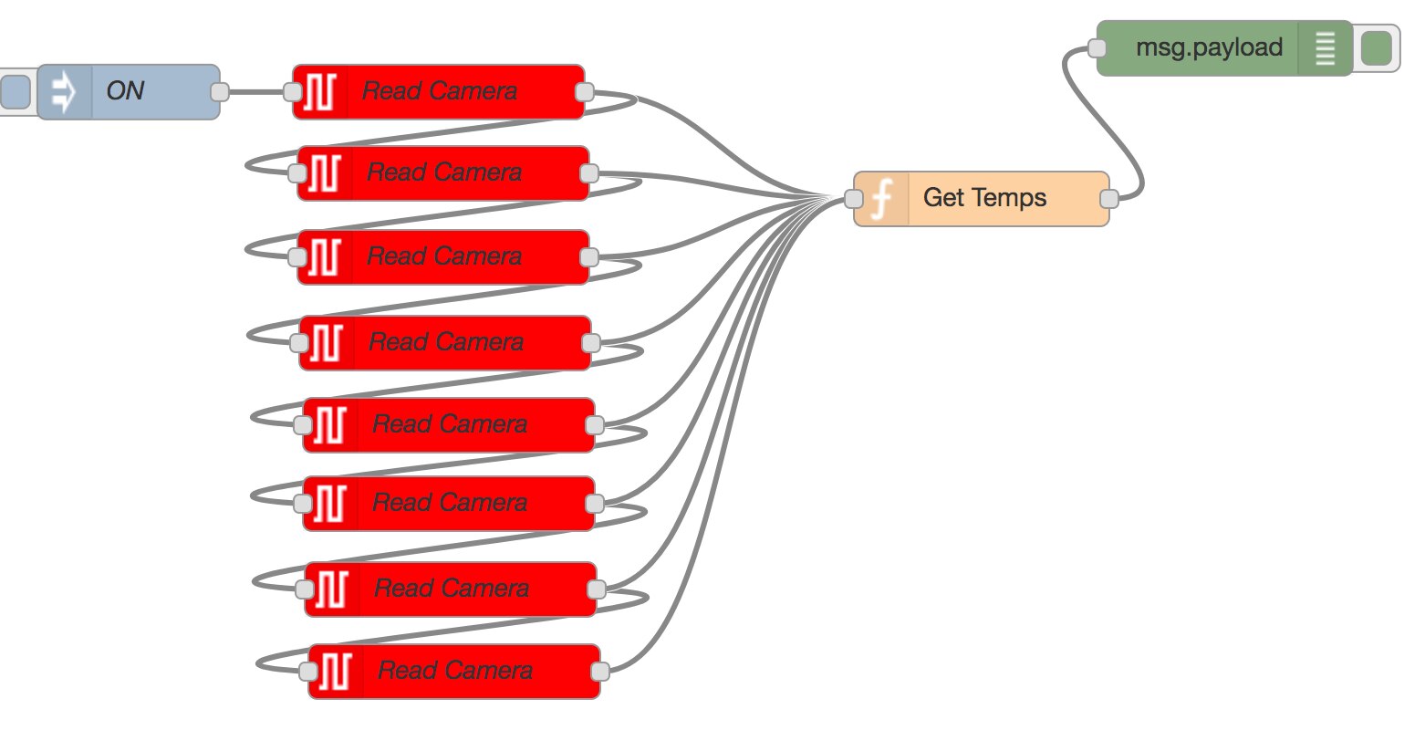
Here is an example flow -
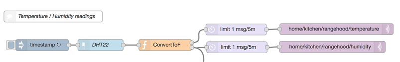
The Timestamp node fires every second. It triggers a reading from the DHT temperature sensor. The DHT data is fed into a "Function" node to convert from C to F and save to global variables; and potentially other logic. We then split the data down two paths - one for temperature and one for humidity. This is sent through a rate limiter of 1 msg every 5 minutes. That then goes into an MQTT node to publish to the home automation server. There is a secondary line coming off the function block which leads down to trigger other flows.
For the most part, the components in this project will be accessed through NodeRed. I think that the notable exception is likely to be the thermal camera to take images and save them to disc. To do this, I will use a node which runs a python script, then in my code check for the directory to be updated meaning a new image is available.
Many things require NPM so I installed that first. In the previous post I discussed setting up NodeRed. Many of the installs I did were done through either the command line or the "Manage Palette" section of the NodeRed interface.
Pi Camera
https://flows.nodered.org/node/node-red-contrib-camerapi
npm install node-red-contrib-camerapi
Big Timer for NodeRed - many different kinds of timer functions similar to CRON jobs.
https://flows.nodered.org/node/node-red-contrib-bigtimer
npm install node-red-contrib-bigtimer
DHT22 -
The DHT Temperature and humidity sensor took some additional work to install. I had done a big write up about using wget to download the prerequisites, then installing the package itself. In the end I never got it to install from the command line and instead found that it was available from Manage Palette. This installed and I was able to get data flowing pretty quickly.
https://flows.nodered.org/node/node-red-contrib-dht-sensor
Playing with the thermal camera
I've had some fun with this camera so far. I started with a pygame script from Adafruit. They provided utilities to both take still images and provide a realtime display.

Here I am sitting in the chair - how do I look???
The raw data returned from the sensor is just temperature readings. This makes doing analysis much easier since there is no conversion from any RGB numbers. I'll do a separate post on how all that works, but here is an example flow where I read out one line of 8 pixels then process them out to the debug window. This is using a manual 'inject' node, then a bunch of I2C nodes to request the data.
ADS1115 - Analog to Digital sensor
The ADC runs on the I2C bus. At first, I tried the I2C node that comes with NodeRed above but documentation seemed sparse and I wasn't able to get good data coming back in. Later, I found a library in palate which added the node, but it failed to install. I went to terminal and used the command
npm install node-red-contrib-ads1x15
but got more errors. I asked Google and found an answer to add "--unsafe-perm" in the command.
sudo npm install --unsafe-perm node-red-contrib-ads1x15
But the node still didn't appear. After some more research, I found that the node-red package was based on a node.js package called node-ads1x15. I went back and installed that complete with sudo and --unsafe-perm. Then reinstalled node-red-contrib-ads1x15. A reboot later and I was in business!
sudo npm install --unsafe-perm node-ads1x15 --save
Here is the new node which was made available.

Conclusion - More posts needed!!!
Well - this post has gotten pretty long. I'll have to stop here and do follow-ups to talk in more detail about the code used and the control algorithms. I think I'd like to break them down by functional block. This particular post was really aimed at showing that all the sensors can be attached and establishing basic communications & control with each of them.
And here you go!
-

genebren
-
Cancel
-
Vote Up
0
Vote Down
-
-
Sign in to reply
-
More
-
Cancel
Comment-

genebren
-
Cancel
-
Vote Up
0
Vote Down
-
-
Sign in to reply
-
More
-
Cancel
Children