


Recap: VitaRF is a small wrist sensor that reads heart rate, blood oxygen (SpO₂), skin temperature and movement, and sends it over Bluetooth to Home Assistant. The idea is simple: keep an eye on someone who lives alone, without making them wear anything bulky, and get help to them fast when something goes wrong.
Past posts
- VitaRF - Part 1 - The Plan
- VitaRF - Part 2 - Interface MAX30102 on NRF52
- VitaRF - Part 3 - Interfacing MAX30208 on NRF52
- VitaRF - Part 4 - Sending Sensor Data to Home Assistant via BLE on NRF52
- VitaRF - Part 5 - Matter over Thread on nRF54L15 with Home Assistant
- VitaRF - Part 6 - An nRF52-Based Heart-Rate & Temperature Wearable PCB for Home Assistant
- VitaRF - Part 7 - Adding a Philips WiZ Smart Bulb to Home Assistant
- VitaRF - Part 8 - Assembling the PCB with Stencil, Paste and a Hot Plate
- VitaRF - Part 9 - Sleep and Fall Detection
This is the wrap-up. It pulls the whole project into one place: what I set out to build, what works today, what doesn't yet, and what comes next. If you want the detail behind any section, the numbered posts above have it.
The idea in one scene
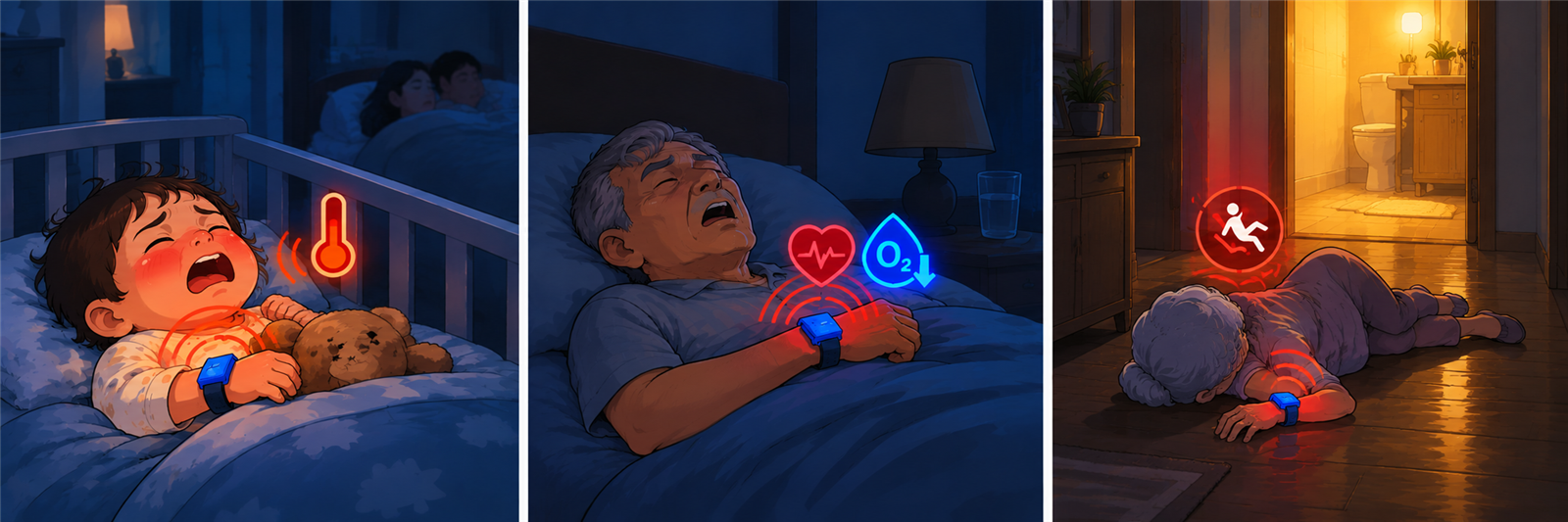
It's 3 am, and the house is quiet. Three families, three different nights, and the same problem: the people who could help are asleep, and by the time anyone knows, it has already become serious.
A baby wakes up crying. She feels hot, her fever is climbing, and her parents are two rooms away. Nobody has noticed yet.
An older man with a breathing condition starts to gasp. His blood oxygen is dropping while he sleeps. His wife wakes to the sound of him struggling, and by the time she finds the phone and the light switch, he has been short of air for a long time.
Someone goes to the bathroom in the dark and falls. Nobody hears it. Their family finds out in the morning, or never.
In each case, the family is alerted only when it is too late. When the alert finally comes, they are half-asleep, fumbling for the light and the phone, trying to work out what is wrong, while the minutes that mattered have already passed.
VitaRF is meant to change the timing. The node keeps watching heart rate, blood oxygen, skin temperature and movement. When a reading or a movement falls outside its normal range, Home Assistant warns the family while the situation can still be handled, not after it has become critical. The same system can turn on the lights, so the family can see the way without fumbling, and anyone who arrives to help walks into a lit room.
That is the core of the idea: the warning comes early, the light comes on, and nobody has to wake up to a crisis in the dark.
Where it stands: the sensing and the fall detection are built. The fall alert and the bedroom light rule are set up in Home Assistant. Early warnings for blood oxygen and temperature are built on a Proof of Concept level. They are the next automations to add.
VitaRF is a prototype, not a medical device. It is not a replacement for a doctor, a thermometer, an oximeter or an emergency service.
Why a wrist
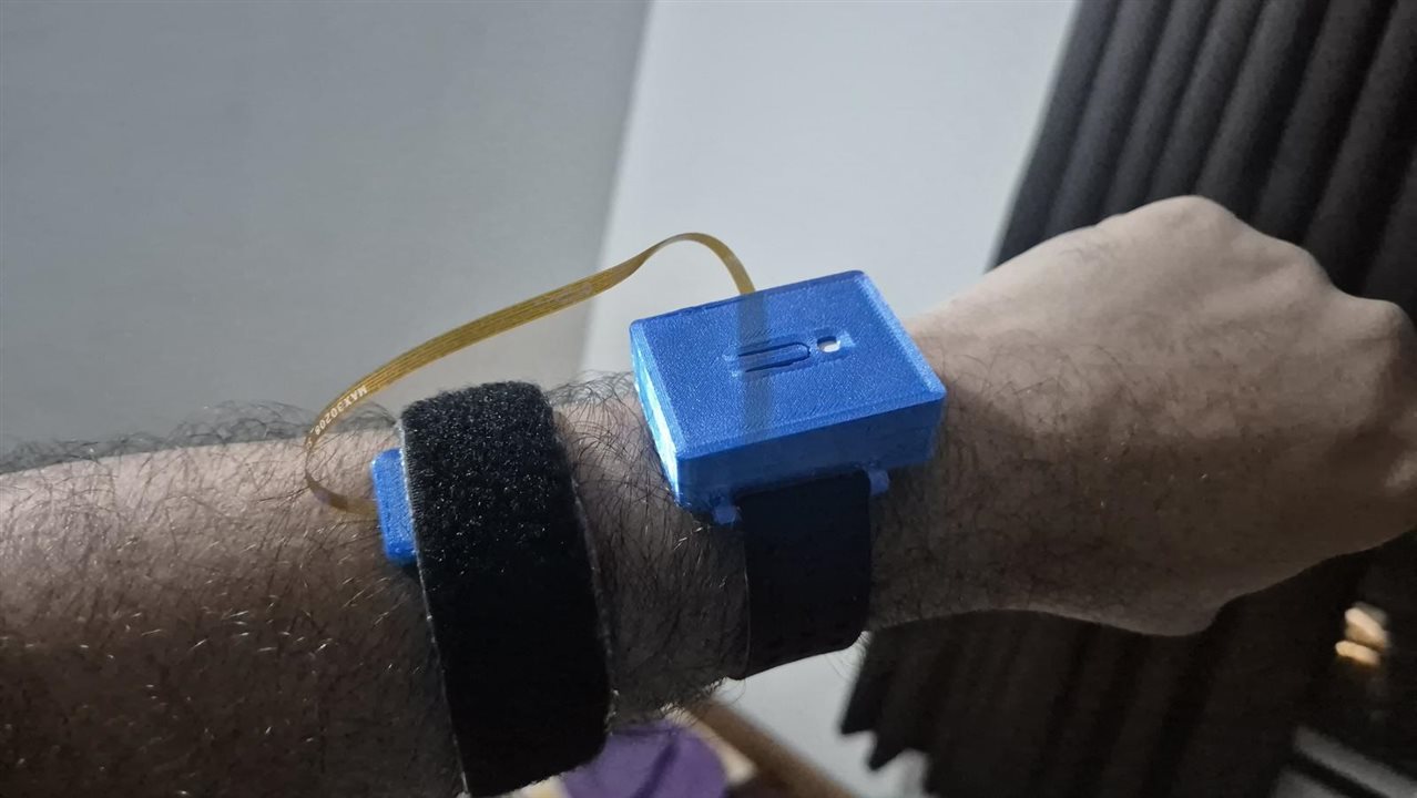
Most health gadgets are either a clinic device or a watch you have to charge every night and remember to wear. I wanted something closer to a plaster: small, light, and something you forget you're wearing. It also had to run for days on a small battery, talk to a home system without a cloud account, and tell the difference between "moving around normally" and "something has happened".
That's three hard problems in one small board. The plan was to solve them in stages.
The three phases
The project was always meant to go in three steps:
- Phase 1, bring-up. Two sponsor sensor boards on a Nordic nRF52832 development kit, sending data over Bluetooth to Home Assistant.
- Phase 2, a real board. One custom PCB with the nRF52832 module, a power chip, an accelerometer and both sensors. Built as five units, each one a wearable.
- Phase 3, a standards-based proof of concept. Matter over Thread, using a second Nordic kit as the sensor and a third as the radio. A stretch goal, meant to show a future-proof path rather than replace Phase 2.
The reasoning was simple: ship something that works early, shrink it once it does, then try the harder architecture last. Phases 1 and 2 are both done as far as the hardware and firmware go. Phase 3 works as a proof of concept on the dev kits.
Key decisions
I build my projects the way I would build a product. That means starting from the constraints and from how the product will really be used. A few decisions shaped everything in this build.
It has to fit the theme. This is a smart home and healthcare project. The LabVIEW trial in the sponsor kit is a capable tool, but it doesn't fit a wearable that talks to Home Assistant, so I left it out of the build.
It has to help most people. A device is only useful if many people can benefit from it. A wrist sensor that reads heart rate, blood oxygen, temperature and movement, and raises a warning when something changes, serves a large group: older people living alone, families with young children, people with breathing conditions. A device that only helps a small group is a different product.
I chose not to add an ECG. I considered an ECG and some AI features. An ECG needs continuous monitoring to be useful, and continuous ECG monitoring usually means the person's condition is serious enough to need a registered doctor close by. That is a clinical product with clinical rules, and it is not the product I set out to build.
I chose not to add AI. Heart rate and SpO₂ from PPG are well-established methods based on signal analysis, and they run well on a small microcontroller. Adding machine learning would mean more complexity, more data and less explainable results. For this problem it would be like using a cannon to kill a mosquito.
So I stayed with simple use cases. The node does a few things well: it measures, it notices when something changes, it warns the people who can help, and it turns on a light. Every step is something I can explain, test and fix, and every threshold can be set by a person.
How I used the sponsor kit
The sponsor kit covered the sensors and some of the shielding. The node itself is my own board, and the kit items became these parts of it:
| Kit item | How I used it |
|---|---|
| MAX30208EVSYS# temperature kit | The MAX30208 sits on a thin flex cable. I use that sensor on the node through its flex connector (J2). The evaluation board's interface chip (a DS2484) is unrelated to the MAX30208 and caused a bus lock-up, so it was removed. |
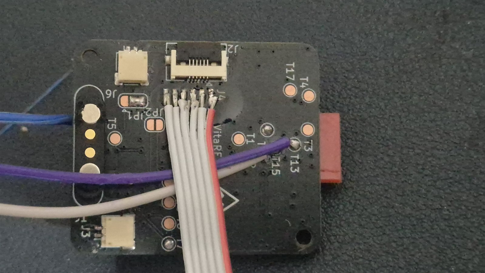
| MAXREFDES117# HR/SpO₂ reference design | I use its MAX30102 optical sensor on the node, connected through a ribbon on J4. The reference board's own circuitry is not part of the node. |
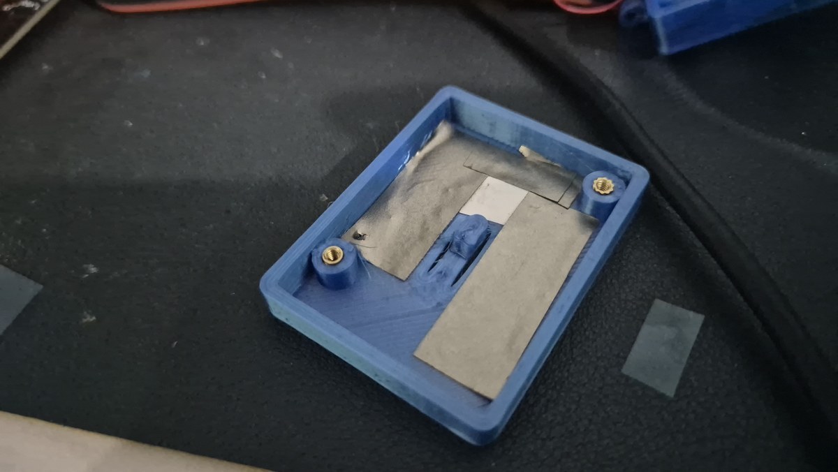
| 3M EMI absorber sheet | Lines the inside of the casing, next to the electronics. |
| Thermally conductive tape | Carries skin heat to the MAX30208 sensor. In my finger test it made the sensor take about a third longer to reach 90 % of its rise. |
| Emerson / NI LabVIEW trial | I Just did not feel like the LabVIew actually made sense in this theme of Smart Home and Health. I mean LabView is really good for research, Industrial Usage or Instrumentation but not at a Home. So I decided not to use it. |
The microcontroller module, the power chip, the accelerometer, the haptic driver and the board layout were my own choices, covered in Part 6.
Part 1: the kit, and the power plan
The sponsored kit came with two Analog Devices sensor boards. The first is the MAX30208 temperature sensor, rated to ±0.1 °C. The second is the MAXREFDES117 heart-rate and SpO₂ reference design, which is built on a MAX30102 optical sensor.
Before soldering anything, I read the datasheets and worked out how the sensors actually run. Both use I2C, and their addresses don't clash, so they can share one bus.
The power side was the first big choice. I wanted one chip for the charger, the battery gauge, the regulators, the status LED driver and the power button. Nordic's nPM1300 does all of that, and since the whole board is Nordic-based, it fits well.
The status LED was a lesson in reading datasheets properly. I'd planned smooth colour fades. The nPM1300's LED outputs are on or off only, with no brightness control. So the status light became a fixed set of colours, with no extra parts needed.
Part 2: heart rate and SpO₂ from a real finger
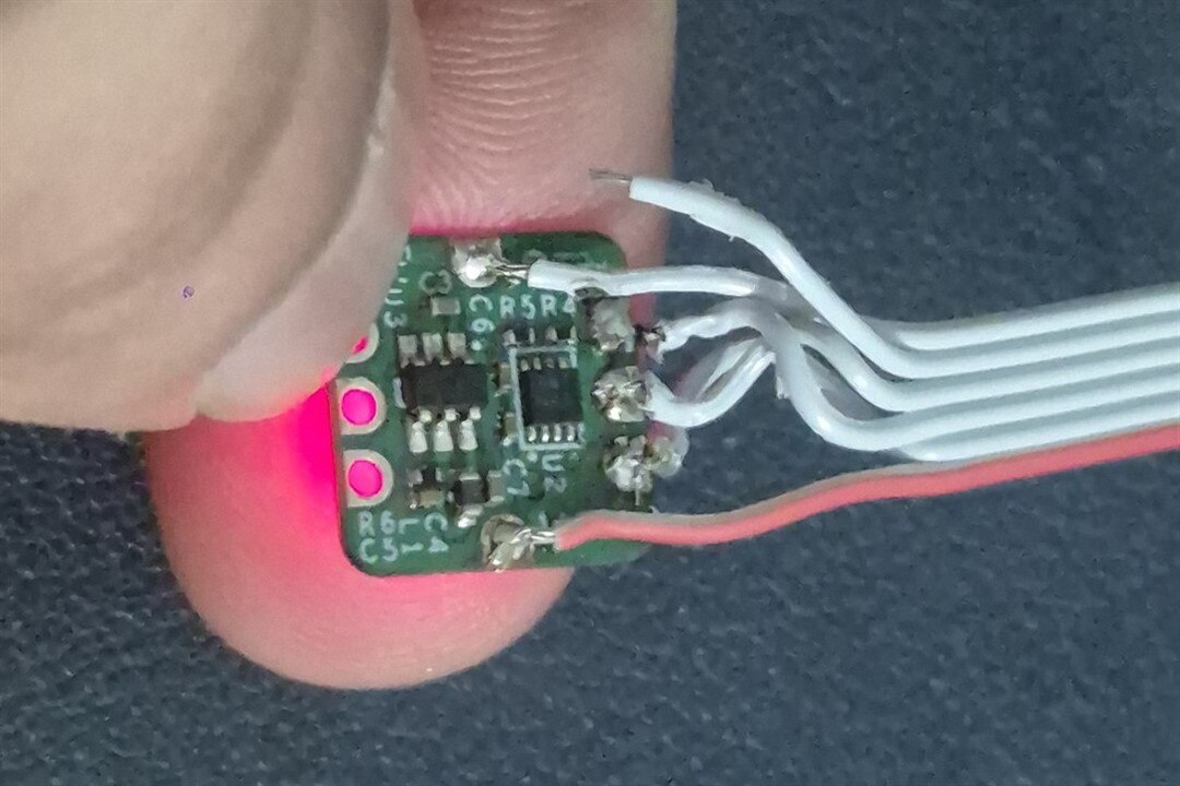
I started on a cheap generic MAX30102 breakout while the kit was still in the post. It uses the same sensor chip as the reference board, so the code would carry over.
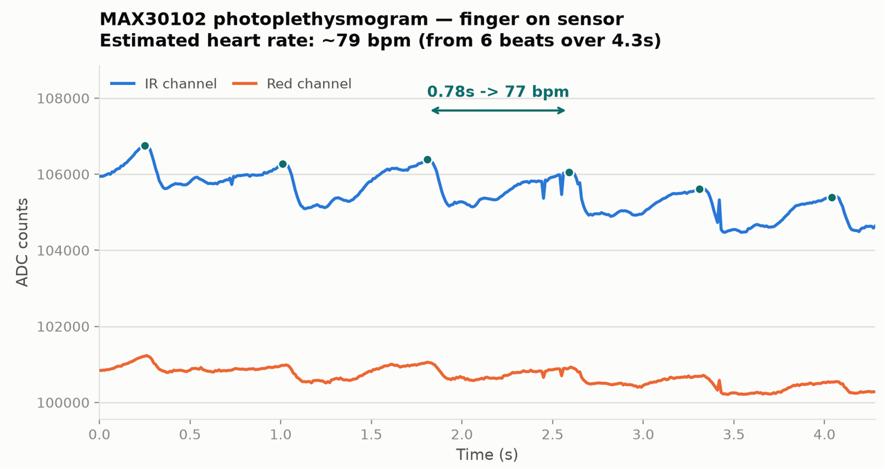
The sensor shines red and infrared light into the fingertip and measures what comes back. Blood moves with each heartbeat, so the light level pulses. The ratio of the red pulse to the infrared pulse tells you the oxygen level. The first job was to get a clean stream of readings: an I2C scan found the sensor, a register readback confirmed the LED settings, and a logging loop drained the sensor's buffer.
To turn those raw numbers into a heart rate and SpO₂, I ported SparkFun's version of Maxim's reference algorithm to plain C. It's a few hundred lines, and it needs a sliding window of four seconds of samples. Two tuning changes were needed before it matched the reference example: the LED current, and how much each window overlaps the last.
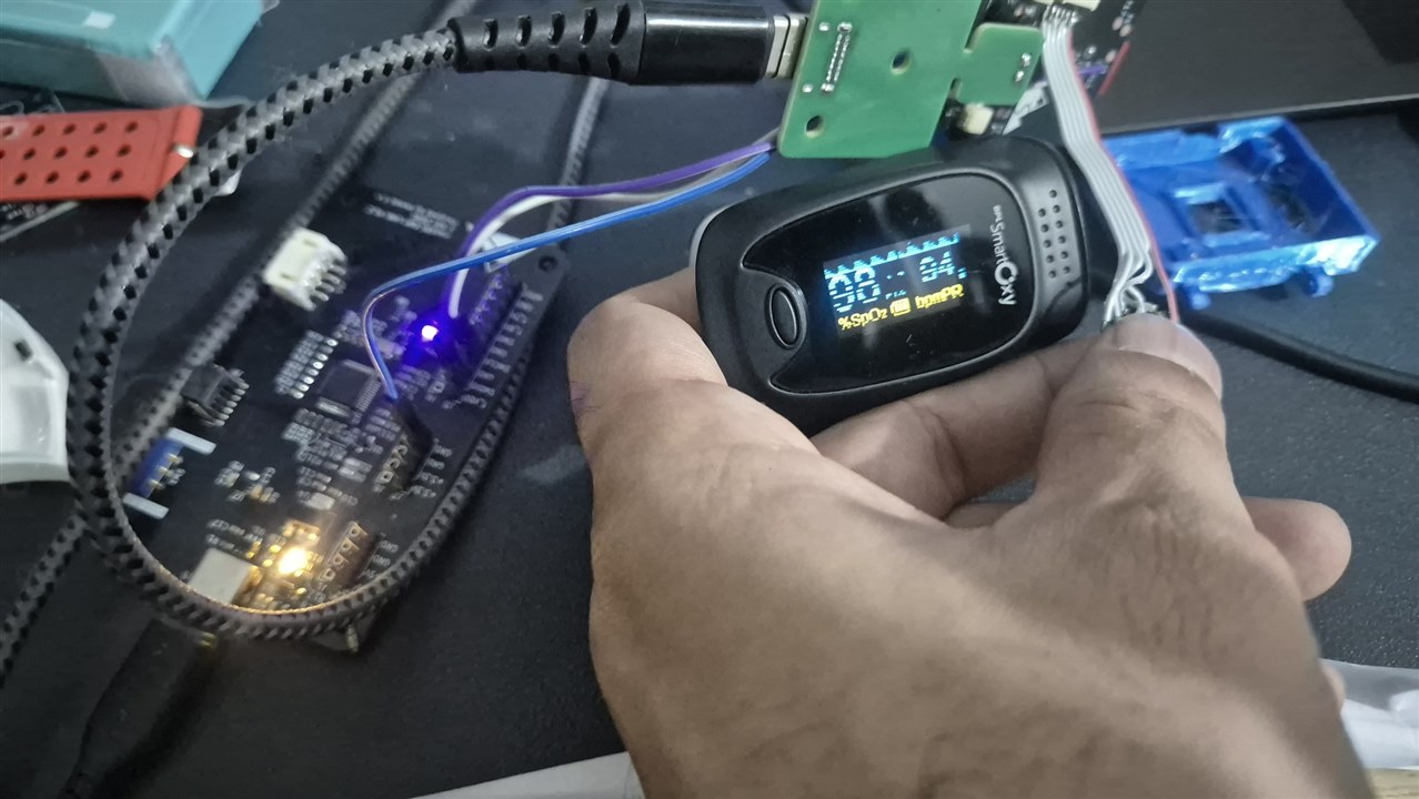
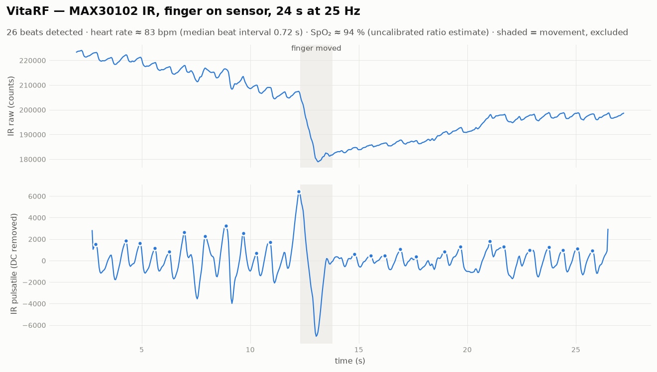
With a finger on the sensor, SpO₂ settled at 98 to 100 %, and heart rate landed in the 71 to 93 BPM range, with a couple of outliers that looked like movement. A separate check with a plain peak counter gave about 73 to 78 BPM on the same kind of capture. I did verify the data from my board to a commercially available Oximeter and although my HRR value seemed correct, it was lagging by a second. SPO2 Measurements were spot on.
Part 3: temperature, and a bus that locked up
The MAX30208 is a precise temperature sensor on a small flexible cable. The cable carries power and the I2C bus to the sensor. Two more pins exist on the chip for an interrupt and a convert-trigger, but they aren't broken out on that flex. So the firmware has to poll for each reading rather than sleep until the sensor wakes it. That costs a little power, but it's manageable.
The driver is short. It starts a conversion, waits for the "ready" bit, then reads two bytes. The datasheet warns not to sample faster than 20 Hz, because a conversion can take up to 50 ms.
Getting there was not smooth. The bus would lock up with the clock line held low, sometimes with a no-acknowledge error, sometimes with the whole program hanging. A logic analyser showed the line was pulled low as soon as power went on, before any code ran. The culprit was a 1-Wire bridge chip on the interface board that the MAX30208 doesn't need. Removing it fixed the bus.
The second problem was a Nordic driver that stays stuck in a "busy" state after a timeout. The fix was to re-initialise the driver when a transfer times out, so one bad transfer can't freeze every later read.
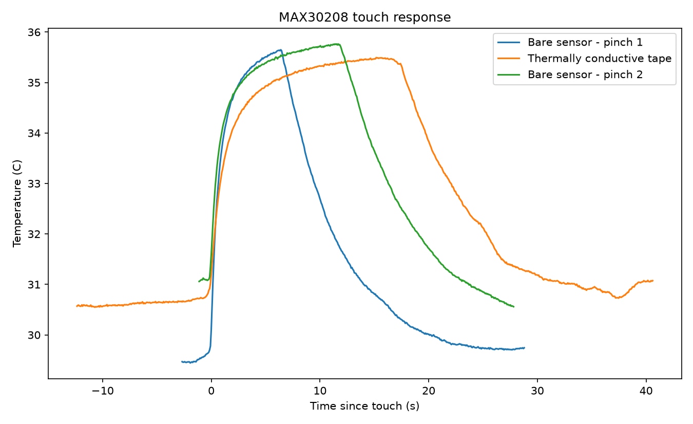
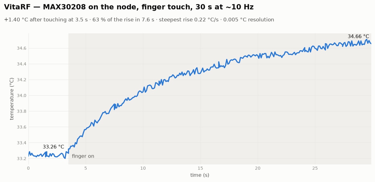
Then I tested the sensor the simple way: pinch it between two fingers and watch the number climb. Ambient was about 29.3 °C. A pinch took it to 35.5 to 35.8 °C, and it fell back when I let go. I tried three cases: a hard pinch, a gentle pinch, and a gentle pinch with thermally conductive tape in between. The tape made the sensor about a third slower to reach 90 % of the rise, and roughly twice as slow to come back down. That matters for a demo, but not for a wearable that sits on skin for hours.
There is thing called contact resistance where when two items touch each other due to microscopic gaps between them, heat is not transferred without resistance, to eliminate them we have to press down hard. To make it more reliable I will use a copper pad as an interface between the skin and the Sensor (with adhesive tape between the sensor and copper). This way, the accuracy of the temperature is less sensitive to how hard you press the sensor on the skin
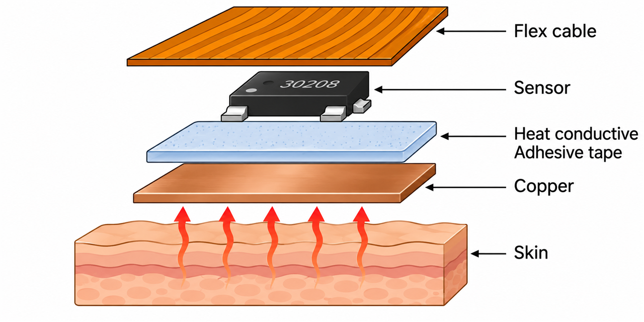
Then with the copper touch pad, the time to settle to 90% of the rise increased to 20+ seconds. Again expected. But for a always on device, fast response time is the last thing on our mind,
Part 4: Home Assistant, and a fake sensor to prove the pipe
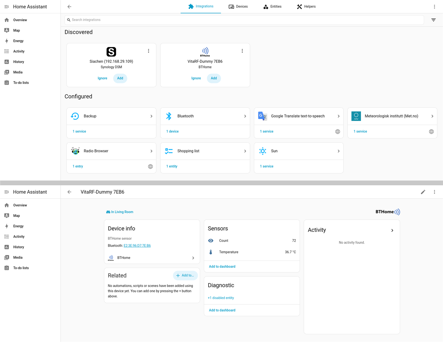
Before wiring the real sensors into Bluetooth, I wanted to prove the path from the chip to Home Assistant worked on its own. So I built two things separately: Home Assistant itself, and a fake sensor that broadcasts made-up temperature and heart-rate values.
Home Assistant runs in Docker on an Arduino UNO Q, which I had on my desk. It took about two hours to download the image, but then it just worked. Home Assistant's Bluetooth integration found the board's Bluetooth adapter on its own.
The fake sensor uses Bluetooth's BTHome format. The big advantage is that Home Assistant discovers BTHome devices automatically, with no custom integration to write. The format has no heart-rate type, so the fake heart rate goes out as a generic count. It shows up as a number called "Count" that you rename in Home Assistant. That's a real limitation, and I'll come back to it.
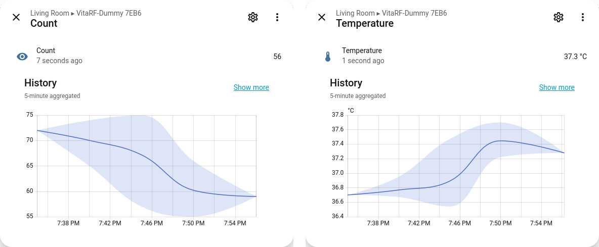
The fake device appeared in Home Assistant as "VitaRF-Dummy", with a temperature of 36.7 °C and a count of 72. Left running, the graphs showed both values wandering in a bounded random walk, updating every five seconds, for two hours without a gap.
Part 5: Matter over Thread, a stretch goal
Bluetooth broadcasting is one-way. Matter is the standard that lets many brands' devices talk to one home system, and Thread is a low-power mesh network underneath it. I wanted to see how that works, so I used two Nordic development kits. The newer one, an nRF54L15, came as a prize from a Matter webinar.
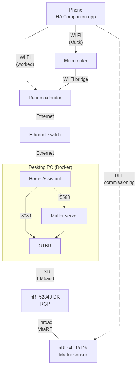
The first kit, an nRF54L15, runs a Matter temperature sensor sample. The second, an nRF52840, runs as a radio co-processor: it's only a Thread radio that the computer drives over USB. The nRF54 is a different chip family, and the older nRF5 SDK I'd used so far doesn't support it. So this part used Nordic's Zephyr-based toolchain, which is a much larger install.
Both boards ran unmodified Nordic samples. The first sign of success was a phone scan showing "MatterTemperature", with the Matter commissioning service on it.
On the computer, I ran an OpenThread border router in Docker, with the radio plugged in over USB. It formed a Thread network called VitaRF. Home Assistant ran in a second container, with a Matter server beside it, and the border router was added through Home Assistant's integrations.
Commissioning from the phone was where things went wrong, twice:
- "Your device requires a Thread border router". The phone didn't have the Thread network's credentials. Syncing them from Home Assistant in the companion app fixed it.
- A pairing that hung for five minutes. Everything on the computer side looked healthy, but nothing reached the border router. The phone then showed "Insecure connection blocked", because Home Assistant was served over plain HTTP on the local network. Changing that security setting got it going. I can't say for certain which change was the fix, so I'm not going to pretend I know.
Once it connected, the device showed a temperature of 8.0 °C. That's not the room. The Nordic sample produces a simulated temperature ramp, and the number changed between checks, which showed the link was live. The path works end to end: Matter device, Thread, border router, Matter server, Home Assistant, and the phone. Phase 3 is a proof of concept, not part of the wearable.
Part 6: the board
The Phase 2 board is one small two-layer PCB, about 30 by 35 mm, designed in KiCad and built as five units. Every unit carries both sensors. My first plan was one sensor per unit, but a single board with both sensors is simpler to build and to test. The schematic is split into four sheets: top level, power, MCU and sensors.
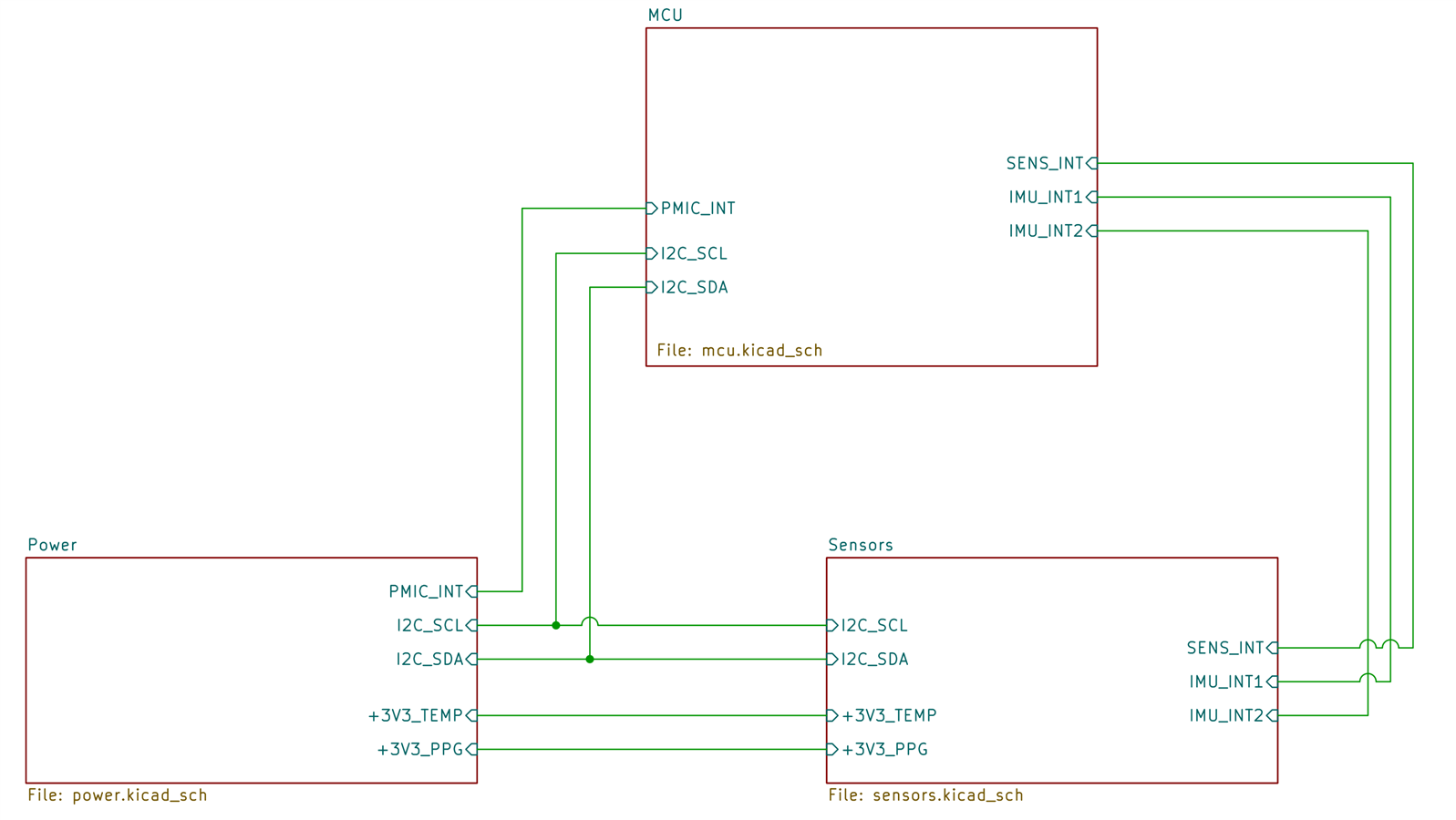
The MCU. I used a RedBear MB-N2 module. It's an nRF52832 with the antenna matching and the 32 MHz crystal already on board, so I didn't need to route a fiddly RF feed on a 1.6 mm board. I added a 32 kHz crystal for low-power timing and the DC/DC converter parts the chip needs for efficiency.
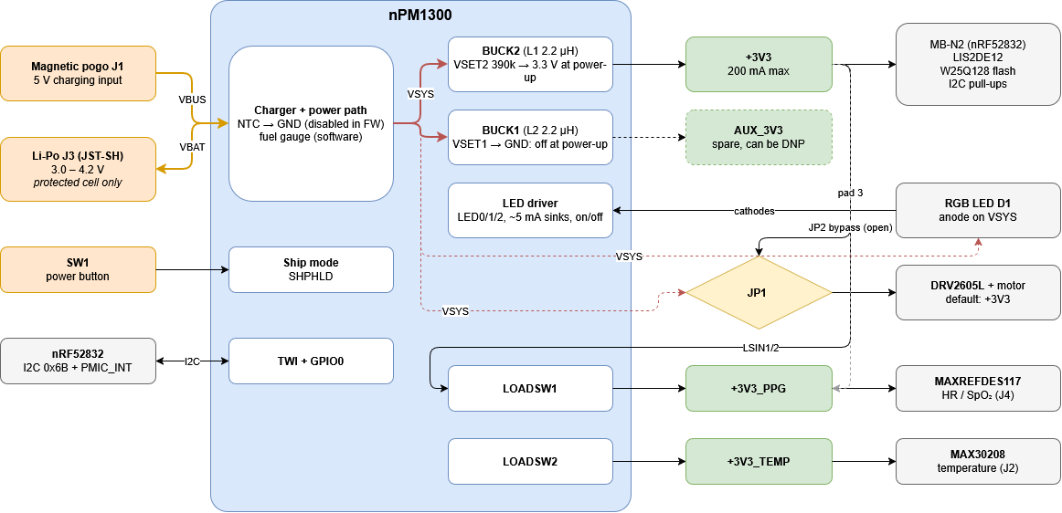
The power. The nPM1300 charges the battery, reads its level, makes the 3.3 V rail, and switches power to each sensor separately. That last part matters: each sensor gets its own switched rail, so firmware can turn a sensor off completely between readings. Charging is through a 2-pin magnetic pogo connector, so there's no USB port to seal against sweat and dust.
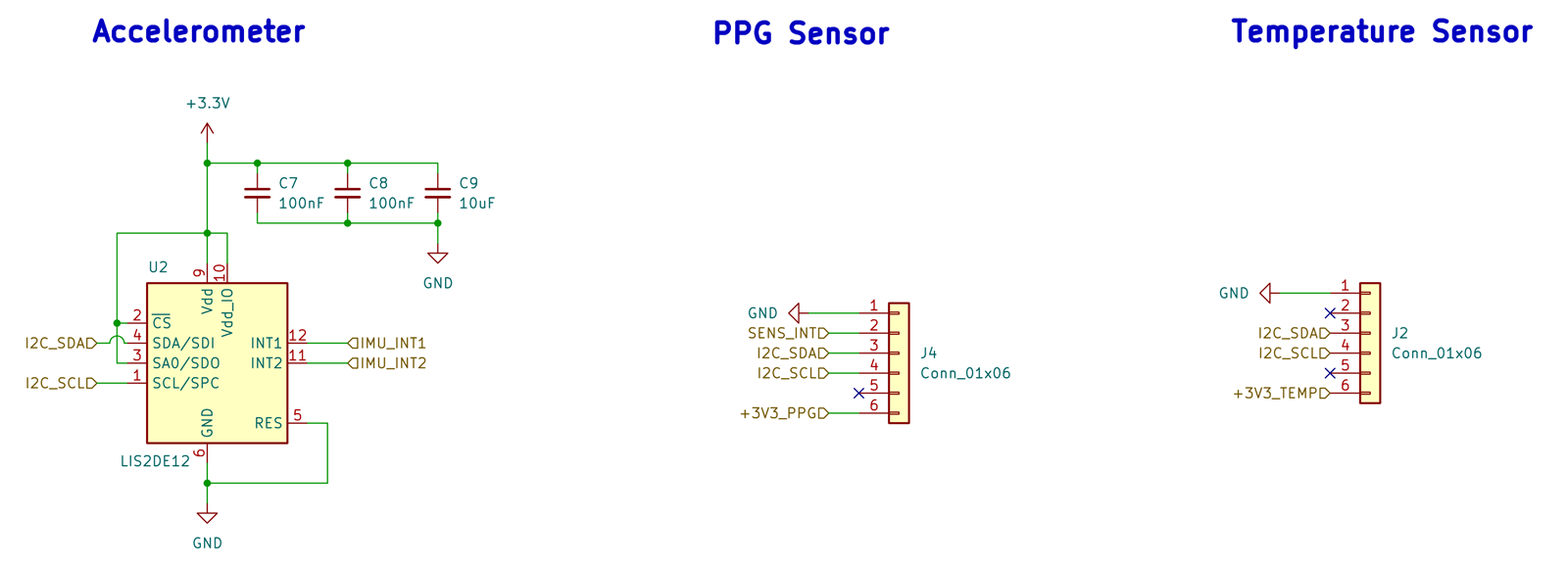
The sensors. The accelerometer (ST LIS2DE12) sits on the shared bus, with two interrupt pins for fall and motion. Two connectors take the sensor boards: one for the MAXREFDES117 ribbon and one for the MAX30208 flex.
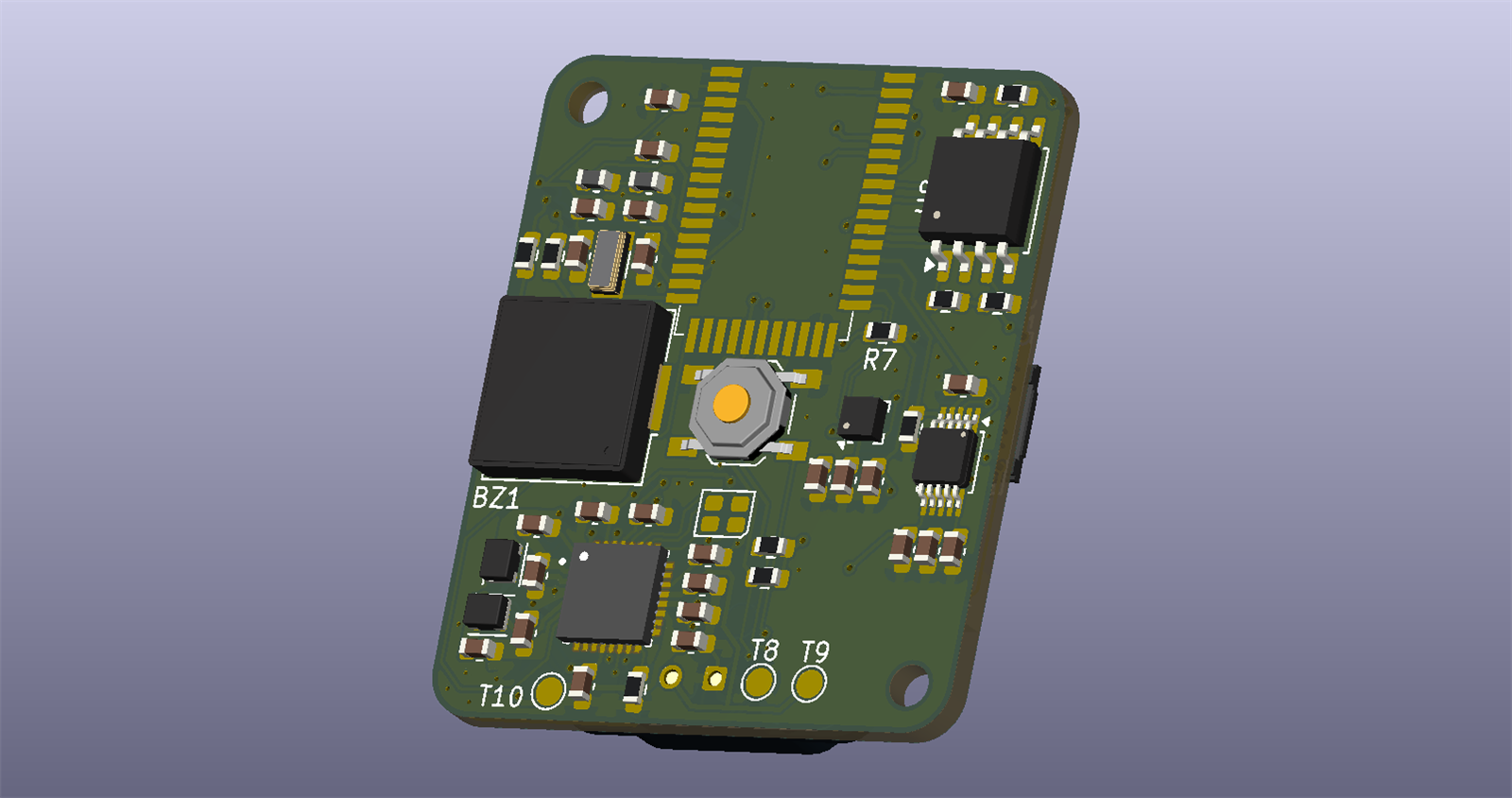
The layout. The chips sit on top, the connectors on the bottom. The power parts are grouped in one corner to keep the switching loops short.
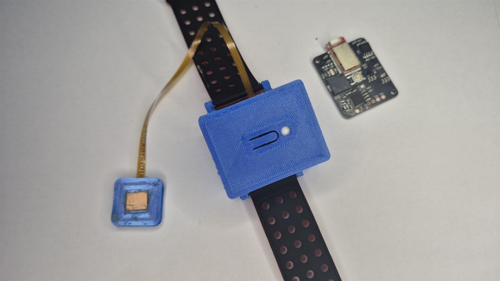
The inside of the casing is lined with a 3M EMI absorber sheet from the sponsor kit. It absorbs electromagnetic noise inside the small plastic shell. This is hard to show in a demo, because the effect is in what does not happen. But it matters for three reasons. First, it helps the device pass electromagnetic compatibility testing, which any device sold as a health-related product will need eventually. Second, it keeps the radio and the switching power circuits from disturbing the sensors, so the heart-rate and temperature readings stay steady. Third, it makes the wearable more stable in use, because a noisy board can reset or misbehave in ways that are hard to trace. I have not measured any of this yet. Those claims are the reason for lining the casing, and the test I still need to run is a comparison of readings with and without the sheet. One Aspect I should highlight is that the majority of the thickness of the sheet is that of the backing tape which is to be thrown away, and it's quite hard to peel them apart
Part 7: the bulb, and the lights idea
While the boards were being made, I added a smart bulb to Home Assistant. I bought a Philips WiZ bulb. The bulb only talks on 2.4 GHz, and its setup app happily lists my 5 GHz network. I picked that one, and the bulb refused to join. The setup screen said "Wrong password", but the password was fine. The real reason was the band.
Once the bulb was on the 2.4 GHz side of the network, Home Assistant found it on its own. It appeared in the Bedroom with an on/off switch and a colour control, and I could change its colour from the dashboard.
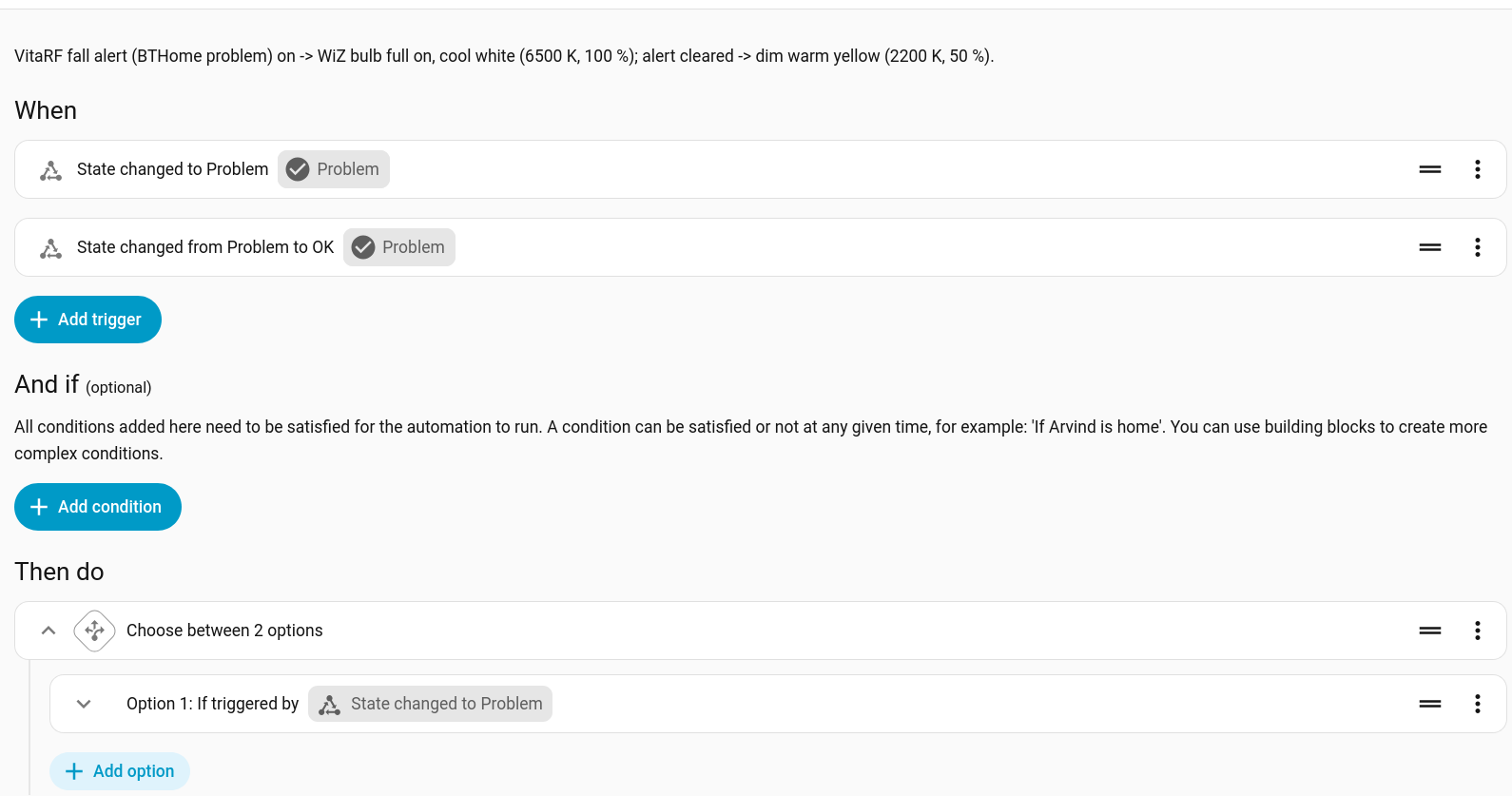
That's the piece the lights idea depends on. Home Assistant can switch the bulb, and there is now a rule that links the fall alert to it. When the alert turns on, the bulb goes to full cool white at 100 %. When the alert clears, it goes to dim warm yellow at 50 %.
Part 8: assembly
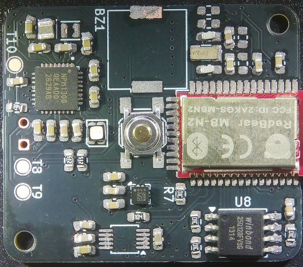
The bare boards came back from JLCPCB, and JLCPCB only made the boards. The assembly was mine. I used a stencil to apply solder paste, placed the parts by hand, and reflowed the board on a hot plate. The video of the process is in Part 8.
It's slow work, and it tests your patience. Careful placement of the QFN parts and the module is the part that counts. The assembled boards came out clean. I haven't found an error in the build so far
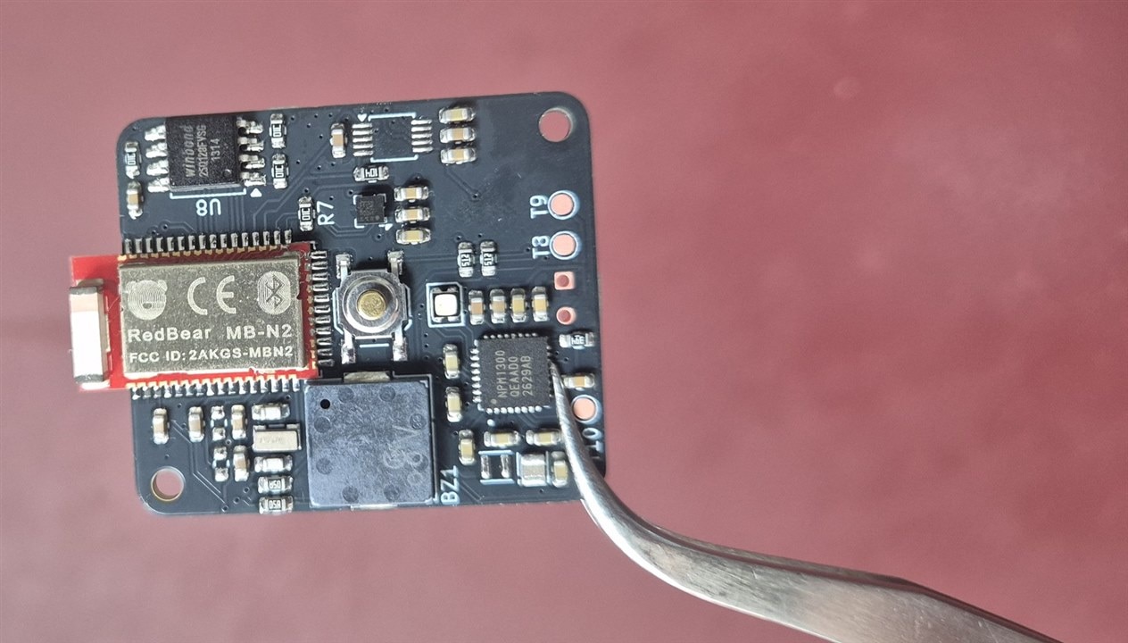
To Ensure a good heat transfer between the skin and the Temperature sensor, I am using a small 1cm square 0.5mm thick Copper as an interface between the skin and the sensor via the heat conducting Adhesive tape. Below is the video of the assembly of the sensor assembly.
Part 9: one accelerometer, two jobs
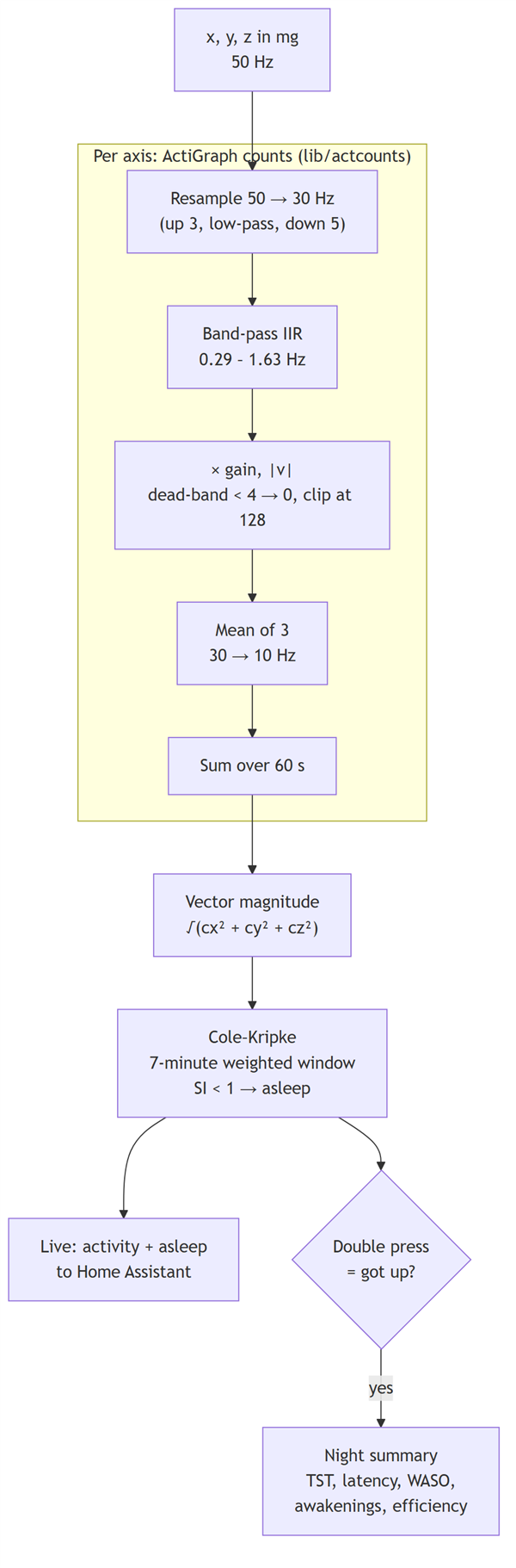
The LIS2DE12 is an 8-bit accelerometer, and it does two jobs from the same stream of data: sleep and falls.
Getting data out of it. The sensor keeps the last 32 samples in a buffer. The node reads it every 400 ms in a single I2C burst, so the processor doesn't wake 50 times a second. One detail the datasheet doesn't spell out well: the buffer count is one less than the number of unread samples. Measuring on the board sorted that out.
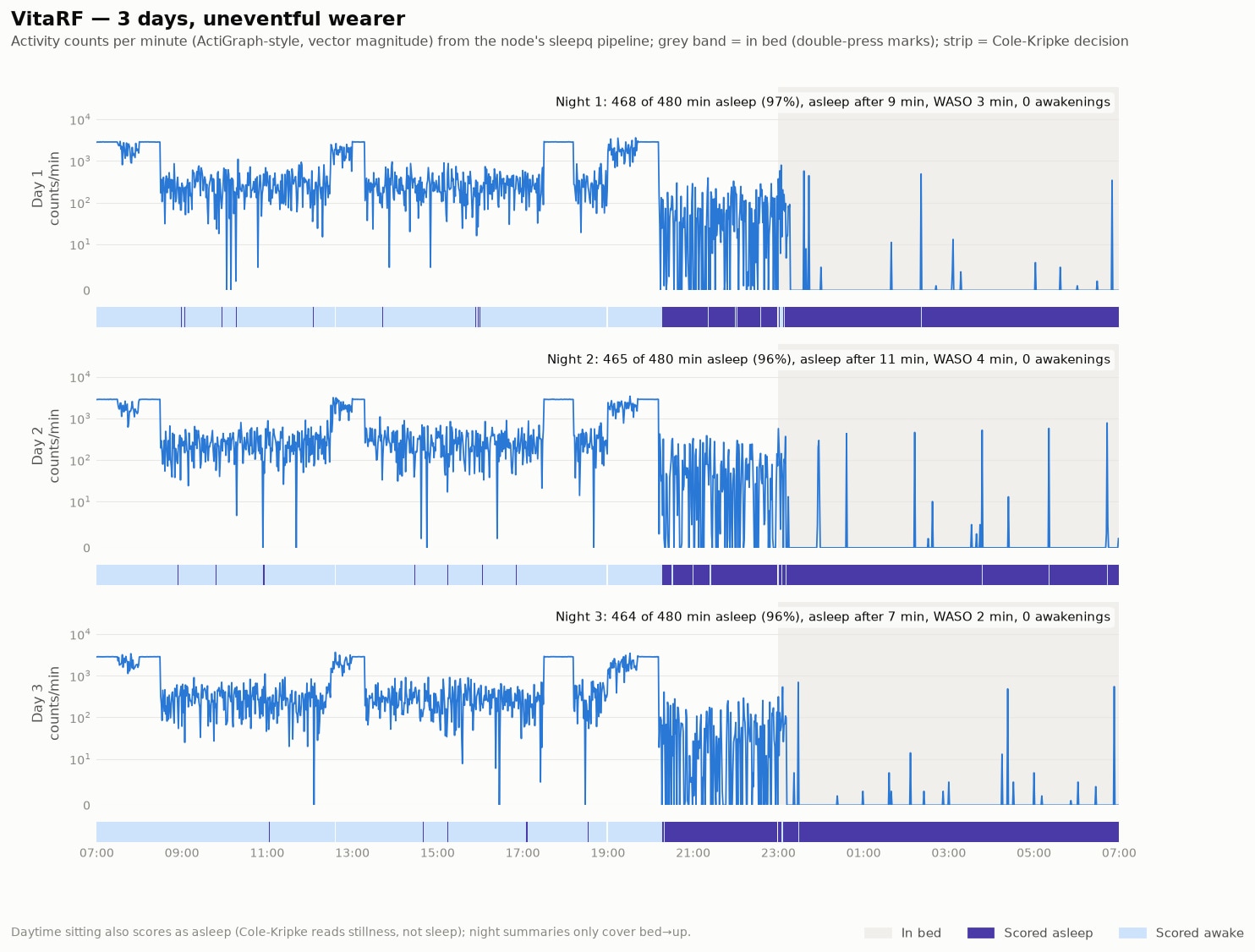
Sleep. Each minute, the node scores whether you are asleep or awake. The method is Cole–Kripke (1992), built on activity counts. The counts follow ActiGraph's published algorithm. I checked my C version against ActiGraph's own reference recordings, and it matched the published counts apart from one-off rounding differences. The sleep scoring matched the published formula exactly on 15,000 random minutes.
Two rules keep the sleep results honest. The node doesn't guess when you went to bed. You double-press the button to mark bed, and again to mark getting up. And lying still on the sofa scores as sleep, so the live "asleep" flag shouldn't be trusted on its own during the day.
Falls. The fall detector looks for three things in order: a short drop, where the sensor reads close to zero g; a hard hit; and a few seconds of stillness afterwards. The thresholds live in one config struct, so they're easy to tune. The first walking test set off false alarms, so the free-fall threshold went from 600 mg to 400 mg. Most published thresholds come from sensors on the waist or chest, and arm swing on the wrist pulls the reading lower than that.

On the test traces I built, a fall was caught. Walking, sitting down hard and a table slam were not flagged. A jump followed by standing still did set off a false alarm, which is one of the known weak spots.
After a fall, the wearer gets a chance to say no. A confirmed fall starts a 15-second countdown. The LED blinks red, the motor buzzes and the buzzer beeps. One press of the button cancels it. If nobody presses, the alert latches: Home Assistant's fall sensor turns on, and the node speeds up its messages for 30 seconds so the alert arrives quickly.
The 3-day run. To see how the sleep and fall code behaves over days, I ran 72 hours of wrist data through the same firmware logic. The chart below shows three nights. Each night had 480 minutes in bed, with 96 to 97 % efficiency and 7 to 11 minutes to fall asleep. The fall detector raised no alerts in the whole run.
How it all fits together
Here is the data path, from the sensors to Home Assistant:

- very 10 minutes**, the node wakes the heart-rate sensor for about 30 seconds, takes a median reading, puts the sensor back to sleep, then reads the temperature three times and averages it.
- All the time, the accelerometer feeds the fall detector and the sleep pipeline.
- Every reading goes out over Bluetooth in BTHome format, so Home Assistant picks it up with no custom integration. Readings also go to a 16 MB flash chip, so nothing is lost when Home Assistant is out of range.
- On boot, the node runs a self-test on every part. With all parts fitted, it passed 11 of 11.
- The button cancels a fall alert, marks bed and up, and clears an alert.
The one thing that's not obvious from the diagram is the heart rate. BTHome has no heart-rate type, so it goes out as a generic count. In Home Assistant it shows as "Count", and you rename it. SpO₂ has the same problem. It goes out as a percentage in the humidity object, so Home Assistant labels it Humidity.
What else this can automate
Once the readings reach Home Assistant, each rule is an ordinary automation that can control lights, speakers, plugs or any device Home Assistant can reach. The ideas below are not built yet. The threshold values are examples only, and should be set with a doctor's advice for each person.
- Early blood-oxygen warning: if SpO₂ stays below a set level for a set time, notify the family and turn the bedroom light to bright white.
- Fever watch: if skin temperature stays above a set level, notify the family. Skin temperature is only a rough guide to fever, so this prompts a check with a real thermometer rather than replacing one.
- Night path light: when the node reports that the wearer has got up, turn on a dim, low light along the route to the bathroom, so the trip isn't a bright wake-up.
- Quiet nights: keep the lights off unless an alert is active, so ordinary night-time trips stay calm.
- Long stillness: notify the family if the wearer has not moved for an unusually long time during the day.
- Heart-rate trend: notify the family if resting heart rate rises sharply and stays high for several minutes.
- Room routines: set the bedroom light to follow the asleep flag, so the room settles when the wearer goes to bed and wakes when they get up.
What works today
- The board is assembled, and the node firmware boots and self-tests all its parts, 11 of 11 with everything fitted.
- Heart rate and SpO₂, from a real finger, on the development board.
- Temperature, from a finger pinch, with and without the thermal tape, on the development board.
- Home Assistant takes BTHome data over Bluetooth. The fake sensor proved that path end to end. The node's own entities in Home Assistant still need checking.
- The sleep scoring and the fall detector pass their host tests on the PC.
- The Matter path works end to end on the dev kits.
- A smart bulb switches from Home Assistant, and a fall-alert automation changes its colour and brightness when the alert turns on or clears.
What's next
- Test the light automation with a real fall, from the alert on the wrist to the bulb in the room.
- Send the alert to a phone or a family member.
- Record real nights and a set of labelled falls, then tune the thresholds on that data.
- Run the full node overnight, and check each Home Assistant entity.
- Move Home Assistant to the Radxa Q6A once the other project releases it, and work on the Matter path from there.
Code highlights
The whole node is open source, but three pieces show how the idea works in code.
1. Sleep or wake, in integer arithmetic. Each minute is scored with the Cole–Kripke method. The check runs on the MCU without floating point:
bool sleepq_cole_kripke_asleep(const uint16_t *counts, uint16_t n, uint16_t i)
{
    uint32_t sum = 0;
    for (int8_t k = 0; k < 7; k++)
    {
        int32_t idx = (int32_t)i + CK_FIRST_OFFSET + k;
        if (idx < 0 || idx >= (int32_t)n)
        {
            continue; /* zero padding */
        }
        uint32_t c = counts[idx];
        if (c > CK_COUNT_CAP)
        {
            c = CK_COUNT_CAP;
        }
        sum += (uint32_t)k_ck_weight[k] * c;
    }
    return sum < CK_SLEEP_LIMIT;
}
2. Every sample goes to both detectors. The motion service feeds each accelerometer sample to the fall detector and the sleep pipeline. A fall that is confirmed starts the 15-second countdown:
static void feed(const lis2de12_mg_t *mg)
{
    fall_event_t fe = fall_detect_feed(&s_fall, mg->x, mg->y, mg->z);
    if (fe == FALL_EVENT_CONFIRMED && s_countdown_ticks == 0 && !g_app.fall_alert)
    {
        start_countdown();
    }
    else if (fe == FALL_EVENT_CANDIDATE)
    {
        NRF_LOG_DEBUG("Fall candidate, checking the aftermath.");
    }

    if (!sleepq_feed(&s_sleep, mg->x, mg->y, mg->z))
    {
        ...
3. What goes over Bluetooth. Each advertisement packs the readings that are valid at that moment. Missing sensors are left out rather than sent as zeros:
static void encode_payload(void)
{
    bthome_t *b = &s_bthome;
    bthome_begin(b);
    bthome_add(b, BTHOME_OBJ_PACKET_ID, ++s_packet_id, 1);
    if (g_app.temp_valid)
    {
        bthome_add(b, BTHOME_OBJ_TEMPERATURE, (uint16_t)g_app.temp_cdeg, 2);
    }
    if (g_app.hr_valid)
    {
        bthome_add(b, BTHOME_OBJ_COUNT_U8, g_app.hr, 1);
    }
    bthome_add(b, BTHOME_OBJ_GENERIC_BOOL, g_app.asleep ? 1 : 0, 1);
    bthome_add(b, BTHOME_OBJ_CHARGING, g_app.charging ? 1 : 0, 1);
    bthome_add(b, BTHOME_OBJ_PROBLEM, g_app.fall_alert ? 1 : 0, 1);
    if (g_app.spo2_valid)
    {
        bthome_add(b, BTHOME_OBJ_HUMIDITY_U8, g_app.spo2, 1);
    }
    bthome_add(b, BTHOME_OBJ_COUNT_U16, g_app.activity, 2);
    bthome_add(b, BTHOME_OBJ_COUNT_U16, g_app.last_sleep_min, 2);
    ...
}
The full files are in firmware/lib/sleepq.c, firmware/vitarf_node/app_motion.c and firmware/vitarf_node/app_ble.c.
Extra things
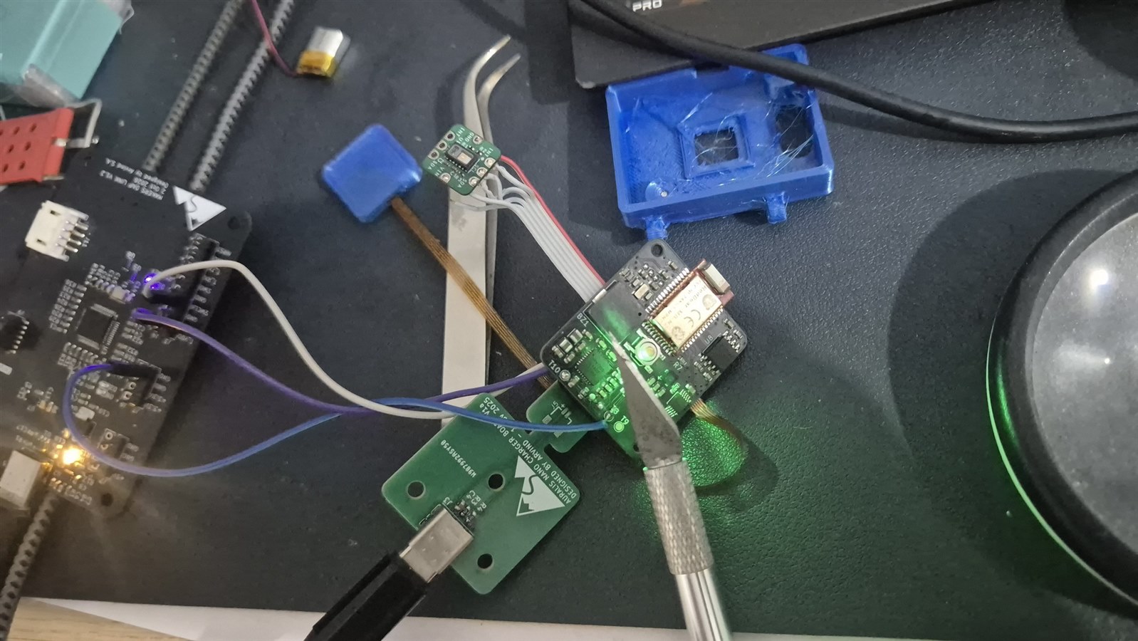
The board is small and crowded. There was no room for a 10-pin ARM debug connector with 1.27 mm pitch, so I didn't fit one. Instead I soldered test points by hand for programming and debugging, and wired the programmer to them for the first flash.
For debugging in the field, I used the LED and the buzzer. The boot self-test checks each part and shows the result on both: a failing part shows up as a pattern on the LED and the buzzer, so I can tell what went wrong without a computer attached.
Status codes
If you ever build this design, these are the lights and sounds the node uses, so you can read it without a computer.
At boot, the self-test
| Pattern | Meaning |
|---|---|
| One short beep and a green blink | All parts present |
| A long low tone and a red light, then N short beeps and N yellow blinks | Part N failed. Repeats for each failed part |
| N | Part | N | Part |
|---|---|---|---|
| 1 | nPM1300 (power chip, LED, rails) | 5 | MAX30208 temperature |
| 2 | LIS2DE12 accelerometer (keep the board still for its self-test) | 6 | DRV2605L haptics |
| 3 | W25Q128 flash | 7 | Buzzer |
| 4 | MAX30102 heart rate and SpO₂ | 8 | Bluetooth stack |
A failed part also shows as a magenta blip every 5 seconds, and a part that goes missing later is reported with a low beep and a magenta flash.
During use
| State | Light | Sound or haptic |
|---|---|---|
| Fall countdown | Red, fast blink | Buzz and beep every second |
| Fall alert, not yet cleared | Red, 1 Hz blink | Short beep every 5 seconds |
| After a vitals check | Green normal, yellow borderline, red bad, magenta no signal | None |
| Charging, or charged | Blue, or green blip every 2 seconds | None |
| Bed or getting up marked | Cyan, 1 second | None |
| Otherwise | Off | None |
Vitals thresholds
| Reading | Borderline | Bad |
|---|---|---|
| Heart rate | Below 50 or above 110 bpm | Below 40 or above 140 bpm |
| SpO₂ | Below 94 % | Below 90 % |
| Skin temperature | 37.5 °C or above | 38.5 °C or above |
Skin temperature at the wrist reads lower than core temperature, so these thresholds are a rough warning, not a fever reading.
Button (SW1)
| Gesture | Action |
|---|---|
| Press during a fall countdown | Cancel it |
| Press while a fall alert is shown | Clear it |
| Short press | Show the last vitals colour for 3 seconds |
| Double press | Mark bed time or getting up |
| Hold for 2 seconds | Measure vitals now |
| Hold for 6 seconds, off the charger | Ship mode. Hold the button to wake |
In the Video above the 4 Yellow Blinks along with beeps signify that MAXREFDES117 is not detected. Actually, It should start with a Red Beep to signify error followed by beep code, but the video is cut off at start.
The code
Everything is in the repository:
- The node firmware,
firmware/vitarf_node - The libraries,
firmware/lib, including the sensor drivers, the sleep and fall code, and the Bluetooth format - The host tests and the 3-day run,
firmware/tests, run withmake testandmake three-day - The board design and fabrication files,
hardware/vitarf-node - A write-up of the firmware,
docs/vitarf-node-firmware.md
Repo Link: https://gitlab.com/arvindsa/vitarf-e14
Final Notes:
It was fun playing with the deep tech of algorithm of extracting information from the sensors. That Part did took a lot of time along with documentation. Let me know if this project was helpful. There are some stability issues in the I2C Transactions, I need to weed that out.
Top Comments
-

Qbit
-
Cancel
-
Vote Up
0
Vote Down
-
-
Sign in to reply
-
More
-
Cancel
Comment-

Qbit
-
Cancel
-
Vote Up
0
Vote Down
-
-
Sign in to reply
-
More
-
Cancel
Children