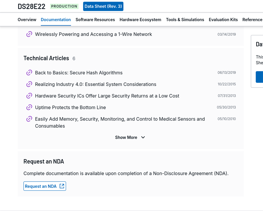
Fair warning, this one is gonna be a hard read. I have used ATECC508A Crypto chip in my work extensively, so I've grown quite comfortable with it. I had couple of chips left over from that work and was delighted to use this challenge to use the Crypto chips again and more importantly document the process in the public. Now, The full datasheet is protected in NDA and you get a very restricted Datasheet online.
Recap:
The idea is simple enough: stop making people swipe a card and type a PIN at every single door. Instead, the ID card (a MAX32630FTHR + ATECC508A in your pocket) unlocks once via PIN, then silently does challenge-response crypto over Bluetooth every time you walk up to a door. If the card gets yanked off you, the IMU detects the tug and it locks itself. No PIN, no entry. For more details check the Part 1 of the series
- Identity Protocol Part 1 - Plan
- Identity Protocol - Part 2 - Django Server
- Identity Protocol - Part 3 - Unboxing and Blinking with Maxim LPSDK
- Identity Protocol - Part 4 - BLE using PAN1326B and BTstack
- Identity Protocol - Part 5 - Interfacing a Keypad
- Identity Protocol - Part 6 - Snatch Detection with the BMI160 IMU
- Identity Protocol - Part 7 - Colouring on the ICLED FeatherWing
Why a Secure Element?
People who were frustrated that their Windows 10 couldnt be upgraded to Windows 11 due to TPM not being available in their device will ask. Why? Because TPM is a secure element, keeps things safe. Similarly this one keeps secrets safe. If you need a refresher into cryptographic encryption should watch the videos below
With the knowledge of the Public and Private key, the question is how can you make a private key secure in an electronics? You can't save in MCU flash, you can dump the firmware and extract it. There are basic protections against it, but it can be countered as well, the private key extracted and the device duplicated. Enter Secure Elements like ATECC508A. This contains specially designed silicon die that you cannot extract the keys, in fact, the keys are generated on the chip and the private key never leaves the chip. You cant even save a private key on the chip for storage, it beats the trust factor. Once the private key is generated, it secure. We can ask the chip to sign a nonce and return the signed value. The keys are stored in slots; access policy for each slot is baked into a "config zone" that you write once and then permanently lock. After the lock there is no going back -- the chip's behaviour is frozen for life.
ATECC508A Primer
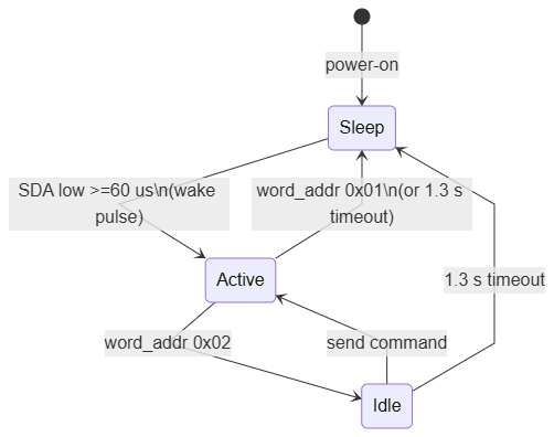
The chip's I2C address is 0x60 .It has four power states:
- Sleep - default on power-up;
- Idle - after the wake pulse, between commands; Note that "TempKey" (a 32-byte scratch buffer used by Sign and other commands) is preserved in idle but lost in sleep.
- Active - executing a command
- Wake transition - triggered by holding SDA low for at least 60 us.
Every transaction follows the same protocol - wake pulse, send a packet composed of [word_addr | count | opcode | param1 | param2 | data | crc16], wait the per-command execution time (Sign takes 58 ms, GenKey 115 ms, Write 26 ms, etc refer the datasheet for the timing.), read the response, then send a 1-byte "idle" or "sleep" word.
The Wake Trick
The datasheet says "hold SDA low for at least 60 us." There is no I2C primitive that does this directly -- I2C masters drive START, address, data, STOP, never a flat 60 us LOW. So either i have to run it as a GPIO and then start I2C. But
Microchip's cryptoauthlib's reference HALs recommend you to to fire an I2C write transaction at slave address 0x00. No real device responds to 0x00, so the master sends START + the 8-bit address byte, gets no ACK, and gives up. But during those 8-9 bit times at 100 kHz, SDA spends most of its time LOW -- about 80 us LOW total.
case ATCA_HAL_CONTROL_WAKE: {
    uint8_t zero = 0x00;
    /* Write to addr 0x00 -- NACK is expected, we use this to flatten SDA */
    I2CM_Write(ATCA_I2C_BUS, 0x00, NULL, 0, &zero, 1);
    hal_delay_ms(WAKE_DELAY_MS);   /* tWHI = 1.5 ms */

    uint8_t wake_resp[4] = {0};
    int ret = I2CM_Read(ATCA_I2C_BUS, addr, NULL, 0, wake_resp, 4);
    if (ret != 4) return ATCA_WAKE_FAILED;
    const uint8_t expected[4] = {0x04, 0x11, 0x33, 0x43};
    if (memcmp(wake_resp, expected, 4) != 0) return ATCA_WAKE_FAILED;
    return ATCA_SUCCESS;
}
CryptoAuthLib HAL: One File
CryptoAuthLib is Microchip's reference C library for the ATECC family. It has all the device-side logic (packet construction, CRC, retry policy, all the opcodes) but expects you to provide a small HAL. This is mentioned in their documentation https://github.com/MicrochipTech/cryptoauthlib/blob/main/lib/hal/README.md . The relevant 4 Functions written in hal_maxim_i2c.c
| HAL function | What it does |
|---|---|
hal_i2c_init |
Bring up I2CM1 MAP_A (P3_4=SDA, P3_5=SCL) at 100 kHz |
hal_i2c_send |
Prepend word-address byte to payload, write via I2CM_Write |
hal_i2c_receive |
Read N bytes via I2CM_Read |
hal_i2c_control |
Implement WAKE (SDA-low trick), IDLE (write 0x02), SLEEP (write 0x01) |
hal_delay_ms/us |
Wrap LPSDK TMR_Delay |
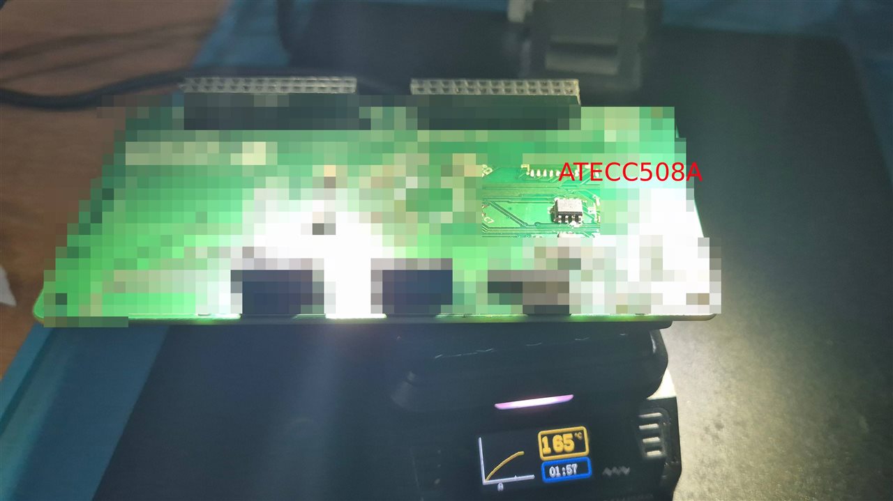
Now, when i started writing the HAL, I inadvertently chose to use an dedicated I2C, used a PCB board from my past work to interface it, so gonna be pixelating the board, It's a simple PCB but it is my policy, I did have to enable the PMIC to enable 3.3V on L3OUT. Now, had i used the I2CM2 which is shared with PMIC and IMU, i would not have seen the crypto chip working and would have had an meltdown. This is because I2CM2 uses I2C pull-ups to 1.8V but ATECC508 requires 3.3V. I think the minimum is some 2v.
Provisioning the Chip
The ATECC508A ships with its config zone unlocked and writable. Provisioning is a four-step rite of passage:
- Write the config zone - 128 bytes that describe what every slot can do.
- Lock the config zone - after this, the slot policies are frozen.
- GenKey in slot 0 - the chip generates a fresh P-256 key pair internally.
- Lock the data zone - after this, no further keys can be written or generated.
Steps 2 and 4 are irreversible. If the config bytes for slot 0 are wrong, you cannot fix them after the lock. So I wanted this to run from a Python script on my laptop where I could see exactly what was being written, dry-run it, and read back to verify, rather than baking the policy into firmware. Unfortunately, I cannot share the Python script because it's sort of paid by my client. Sparkfun who does sell these chips advice you to buy many extra chips in case we mess up.
The Config Zone Template
The 128-byte config zone is a packed bag of bit fields: SlotConfig (16 entries, 2 bytes each), KeyConfig (16 entries, 2 bytes each), Counter[0:1], LastKeyUse, LockValue, LockConfig, ChipOptions, X.509 hints, etc. For this PoC I only care about slot 0:
| Field | Value | Meaning |
|---|---|---|
| Slot 0 SlotConfig | 0x8720 |
IsSecret=1, ReadKey=7, WriteConfig=2 (GenKey allowed) |
| Slot 0 KeyConfig | 0x0033 |
KeyType=4 (P-256), Private=1, PubInfo=1, Lockable=1 |
IsSecret=1 is the line that matters most -- it means the slot's contents (the private key) are never returned by Read. WriteConfig=2 allows GenKey to populate the slot but blocks raw writes. PubInfo=1 makes the public key derivable via GenKey(slot, mode=read), which is how the script reads it back after locking.
The other 15 slots get permissive policies (0x8F0F / 0x3C00) so they could be used later, but for the this project they remain empty.
Signing on the ATECC
Once the chip is provisioned, signing a 32-byte digest is a two-command sequence:
- Nonce pass through (opcode
0x16, param1=0x03) -- loads a 32-byte value into TempKey directly, bypassing the chip's internal nonce generation. - Sign external (opcode
0x41, param1=0x80, param2=slot index) -- signs the contents of TempKey with the P-256 private key in the given slot. Returns a 64-byte signature, with no ASN.1 wrapping. I used ASN,1 a lot, but never understood it.
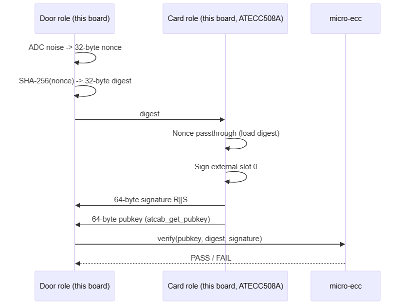
The reason this is two commands instead of one is that the chip's "internal" Sign mode is designed for signing data the chip itself generated (like its own random number plus a counter). For our use case -- signing an external challenge -- we have to load the digest manually, which is what the Nonce passthrough does.
Verifying on the Door
The door device does not have an ATECC508A. Actually In the original proposal i wrote it, but to load all public key from django server is an impossible task, Then i thought, It only needs to verify signatures, not generate them. ECDSA verification is purely arithmetic with public values. there is no key to hide, so no need of secure element, so a software library is enough. I picked Kenneth MacKay's micro-ecc,
It is dropped in as a git submodule under third_party/micro-ecc/. The verify call is one line:
int ok = uECC_verify(pubkey64, digest, 32, signature64, uECC_secp256r1());
Where pubkey64 is the X || Y coordinates (no SEC1 0x04 prefix), digest is the 32-byte SHA-256 of the challenge, and signature64 is the raw singature rteturned in returned by atcab_sign. (Step 2 above).
The End-to-End Bench Test
The same provision-verify firmware full crypto chain on a single board. After provisioning, two extra commands via serial will test the generation of nonce, signing via ATEC508A and veriofication via micro-ecc
| Command | Action |
|---|---|
k |
Read public key from slot 0 via atcab_get_pubkey and print 128 hex chars |
d |
ADC-noise nonce -> SHA-256 -> sign(slot 0) -> read pubkey -> uECC_verify; print PASS/FAIL |
The Nonce Generation Confusion
For sake of my own sanity, i will tell you i tried using the MAX32630 "PRNG' which stands for Pseudo Random Number Generator which surprisingly gave me a constant number always i think It stands for "Persistent, Reluctant Number Guy" with so many work arounds nothing worked. So i went to the age old method of using the ADC. Sample 32 times across 4 channels (128 samples), mix into a 32-bit accumulator with rotate-left-3 + XOR, then expand to 32 bytes via xorshift32: I took this code from somewhere in my past work, It is not really my work, But I've used it successfully.
uint32_t seed = 0;
for (int round = 0; round < 32; round++) {
    for (int i = 0; i < 4; i++) {
        uint16_t val = 0;
        ADC_StartConvert(ch[i], 0, 0);
        ADC_GetData(&val);
        seed = ((seed << 3) | (seed >> 29)) ^ (uint32_t)val;
    }
}
if (seed == 0) seed = 0xA5A5A5A5u;   /* edge case: all channels read 0 */
This produces a different nonce on every reset, verified by capturing NONCE : lines across many reset cycles and checking for repeats (none, ever).
Code for this particular post is available at https://github.com/arvindsa/identity-protocol-e14-challenge/tree/main/firmware/tests/provision-verify
Code for entire project is available at https://github.com/arvindsa/identity-protocol-e14-challenge
Final Notes
We used a decade old crypto algorithm using both an Hardware chip and an software library. My head is boiling trying to ascertain if my post is understandable, if not let me know i will try to rewrite this. Next is using GATT to enable exchange of NONCE and signed digest. The work is done, I just have to write the post