LEDs has been a major part of my projects and I love working with it. My son also loves to see the things i do with my LEDs. In this part i make colors appear on the ICLED Featherwing
Recap:
The idea is simple enough: stop making people swipe a card and type a PIN at every single door. Instead, the ID card (a MAX32630FTHR + ATECC508A in your pocket) unlocks once via PIN, then silently does challenge-response crypto over Bluetooth every time you walk up to a door. If the card gets yanked off you, the IMU detects the tug and it locks itself. No PIN, no entry. For more details check the Part 1 of the series
- Identity Protocol Part 1 - Plan
- Identity Protocol - Part 2 - Django Server
- Identity Protocol - Part 3 - Unboxing and Blinking with Maxim LPSDK
- Identity Protocol - Part 4 - BLE using PAN1326B and BTstack
- Identity Protocol - Part 5 - Interfacing a Keypad
- Identity Protocol - Part 6 - Snatch Detection with the BMI160 IMU
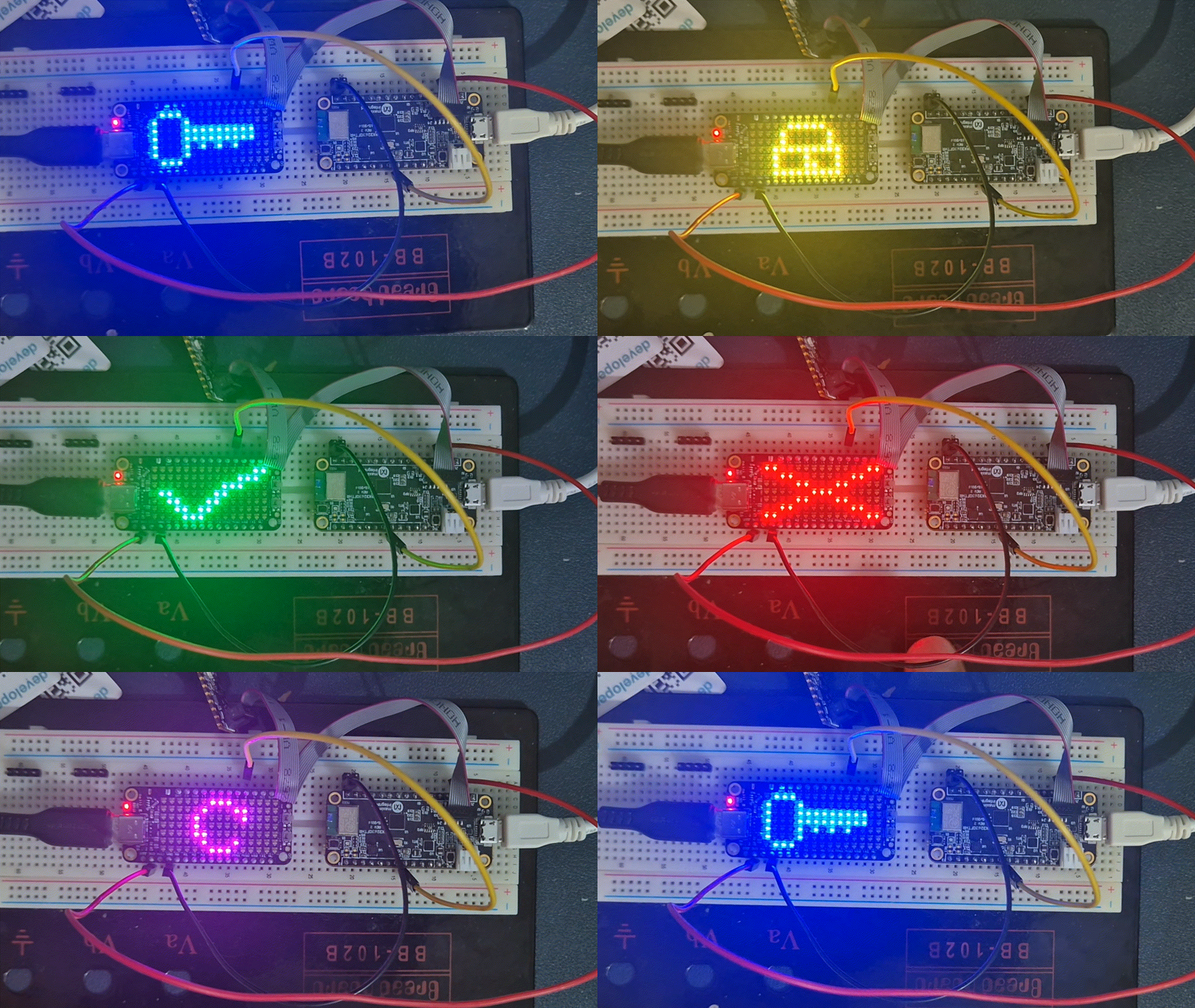
The ICLED FeatherWing is on the door device. It displays status icons: a blue key (waiting), yellow lock (authenticating), green tick (granted), red cross (denied), and magenta sync arrows (server update). 105 LEDs arranged in a 7x15 column-major matrix, single data wire in, GRB colour order. Full source is in `firmware/tests/icled-timer/` (TMR4 hardware PWM) in the project repo.
The WS2812B Protocol
The IC LED FeatherWing contains 1312020030000 LED which i loved working with in my previous challenge AuraAlert - Lighting up Every Sound. Seriously bright with awesome colors. It uses the popular WS2812B Protocol. In the Previous challenge, i never bothered with the protocol as i was using Arduino library to take care of it. This time I have been challenged to make the protocol code from scratch.
The Protocol is quite simple
- For starting a frame, send a 50uS low
- Each LED grabs the first 24 bits of incoming data (8 bits each for green, red, blue) and forwards everything else downstream.
- There is no separate clock line, and so '0' and a '1' are distinguished only by how long the wire stays HIGH within a fixed 1.25 us window.
- '0' is when there is 0.35uS high (T0H) followed by 0.9us of low (T0L)
- '1' is when there is 0.9us of high (T1H) followed by 0.35us of low (T1L)
- In this fashion, i have to provide 8 bit values of LED for Green, Red and blue (in this order)
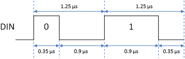
Credits: https://mcuoneclipse.com/2016/05/22/nxp-flexio-generator-for-the-ws2812b-led-stripe-protocol/
I miss my STM32s
Even though most of time I use Arduino Core for STM32 for developing a project fast, there are times when for serious production work, I had to use STM32Hal. There the approach is well established: configure a timer in PWM mode, hook a DMA channel to the timer's CCR register (Capture/Compare Register), fill a buffer with duty-cycle values for every bit, and fire it off. The CPU is completely free during the transfer. One call to `HAL_TIM_PWM_Start_DMA()` and you are done. The DMA engine pushes each duty value into the compare register on every timer period, producing a continuous PWM waveform with the right T0H/T1H timing. No CPU involvement, no interrupt-disable window.
The MAX32630 does not have this functionality, or it probably does and I can't find it. For now, there is no equivalent of the STM32's TIMx_CCR DMA burst mode. So I have two options:
- Bit-bang with NOPs: toggle GPIO directly, pad timing with NOP instructions
- Hardware PWM with polled duty update - use the timer in PWM mode but update the duty register manually each bit period
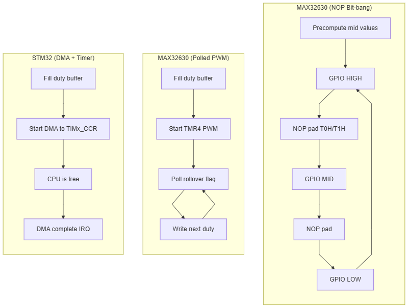
Approach 1: NOP Bit-Bang
Easy to code, very unreliable. Drive a GPIO pin HIGH, wait the right number of NOPs for either a '0' bit or a '1' bit, then drive it LOW, wait again, and repeat. A NOP is "no operation" is a CPU instruction that does literally nothing for one clock cycle. Essentially it like delay() but at a more assembly level. Join many NOPs to get a precise, calibrated delay.
The Feather is clocking at 96 MHz, one CPU cycle is ~10.4 ns. But NOPs do not take exactly one cycle due to APB bus write latency when toggling GPIO. I measured the effective NOP rate at 10.85 ns/NOP by capturing waveforms on a scope.
I tried a lot, but I never got the LED working at all. So I decided to let it rest. At 7x15=105 Led's it will take around 3.2ms for sending data to the LEDs, that will not play well with my 50hz IMU data reading.
Approach 2: Hardware PWM with Polled Duty (icled-timer)
Let the timer peripheral generate the precise waveform timing, and the CPU only needs to update the duty register between bit periods.
Pin-to-Timer Mapping
The MAX32630 maps GPIO pins to timers with the formula (see SYS_TMR_Init in the LPSDK's mxc_sys.c):
timer_index = (port * 8 + pin) % num_timers
For P5_6: (5*8 + 6) % 6 = 4, so P5_6 maps to TMR4. This is the integration target pin for the ICLED DIN on the door device (D13 header position on the FeatherWing).
Timer Configuration
At 96 MHz with prescale TMR_PRESCALE_DIV_2_0 (which is divide-by-1, not divide-by-2; the name refers to 2^0), one tick = 10.42 ns.
| Parameter | Ticks | Time |
| Period (1.25 us) | 120 | 1250 ns |
| T0H duty | 38 | 396 ns |
| T1H duty | 77 | 802 ns |
The timer runs in 32-bit PWM mode. On each period rollover, the counter resets to 0 and the output goes HIGH. When the counter reaches the duty value, the output goes LOW. So by writing 38 ticks as duty we get a ~400 ns HIGH pulse (a '0' bit), and 77 ticks gives a ~800 ns HIGH pulse (a '1' bit).
The Pre-Frame Buffer
Before starting the transfer, the entire frame is pre-computed into a duties[] array, one entry per bit, 105 LEDs x 24 bits = 2520 entries. Each entry is either DUTY_T0 (38) or DUTY_T1 (77).
static uint8_t duties[NLEDS * 24];

/* Build duty array from bitmap */
int idx = 0;
for (int led = 0; led < NLEDS; led++) {
    int col = led / ROWS;
    int row = led % ROWS;
    uint8_t bytes[3] = { pg, pr, pb };   /* WS2812B order: G, R, B */
    for (int i = 0; i < 3; i++)
        for (int bit = 7; bit >= 0; bit--)
            duties[idx++] = ((bytes[i] >> bit) & 1) ? DUTY_T1 : DUTY_T0;
}
The inner loop is simple: poll for the timer's rollover flag, clear it, write the next duty value. The timer hardware handles the precise HIGH/LOW timing. The CPU just needs to update the duty register within the 38-tick window (T0H) of the current bit, plenty of time for a poll+clear+write that takes ~10 cycles.
for (int i = 1; i < NLEDS * 24; i++) {
    while (!TMR32_GetFlag(MXC_TMR4));
    TMR32_ClearFlag(MXC_TMR4);
    TMR32_SetDuty(MXC_TMR4, duties[i]);
}
The Bug That Corrupted Every First Pixel
This is where i spent most of the debugging time. The first pixel was always wrong: LED 0 had a persistent green tinge regardless of what colour i sent. Every other LED was perfect. It turned out by looking at my Logic analyzer that When the PWM timer is stopped, its output pin idles HIGH. Calling GPIO_Config(&din_tmr) to switch the pin from GPIO mode to timer mode immediately connects it to the HIGH timer output. So bit 7 of the first byte (G channel) was always read as a '1' by the strip, regardless of the actual data.
The Fix: Warmup Period + Direct Register Write
The fix is to start the timer while the pin is still in GPIO output-LOW mode. This was experimental, but it worked, I guess the strip sees the LOW as an extension of the reset period. We wait for the first period rollover. Then we switch the pin to timer mode via a single func_sel register write instead of the full GPIO_Config call: Thanks to ChatGPT in helping me solve this.
/* Start timer, pin stays GPIO LOW, strip sees reset */
TMR32_SetCount(MXC_TMR4, 0);
TMR32_SetDuty(MXC_TMR4, duties[0]);
TMR32_ClearFlag(MXC_TMR4);
TMR32_Start(MXC_TMR4);

while (!TMR32_GetFlag(MXC_TMR4));   /* warmup */
TMR32_ClearFlag(MXC_TMR4);

/* count=0, output=HIGH: connect pin now, bit 0 starts cleanly */
MXC_GPIO->func_sel[5] = (MXC_GPIO->func_sel[5] & ~MXC_F_GPIO_FUNC_SEL_PIN6)
                       | (MXC_V_GPIO_FUNC_SEL_MODE_TMR << MXC_F_GPIO_FUNC_SEL_PIN6_POS);
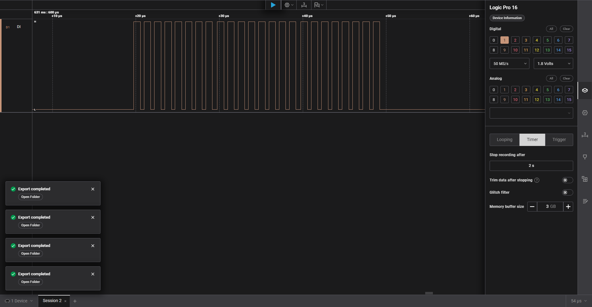
This is the waveform of full brightness of one single LED. This was taken when i used one single WS2812B 5050 with adafruit adapter to test out if the green led bug was not repeated on a known led. Fixed the problem while it was attached on it. Forgot to capture waveform on the ICLED. I promise to take better waveform capture in the future.
LED Matrix Layout
The ICLED FeatherWing is wired such that LED0 is top-left (row 0, col 0), LED 6 is bottom-left (row 6, col 0), LED 7 is top of column 1 (row 0, col 1), and so on. This is considerably different from the Serpentine wiring in the projects i've done at Connect 4 Game or even a recent Custom LED Matrix screen which I had built for a client
LED index = col * ROWS + row
This means when sending pixel data, we iterate through columns left to right, and within each column top to bottom. The bitmap arrays in the code are stored as [row][col], so the send loop does the transpose:
The Five Auth-State Icon
I designed five 7x15 pixel bitmaps for the door device status display. Two examples in ASCII art below; all five are in
. X X X . . . . . . . . . . .
X . . . X . . . . . . . . . .
X . . . X X X X X X X X X . .
X . . . X X X X X X X X X . .
X . . . X . X . X . X . . . .
X . . . X . . . . . . . . . .
. X X X . . . . . . . . . . .


. . . . . . . . . . . . . X X
. . . . . . . . . . . X X X .
. . . . . . . . . X X X . . .
. X X . . . . . X X . . . . .
. . X X . . . X X . . . . . .
. . . X X . X X . . . . . . .
. . . . X X X . . . . . . . .
Results
All five icons cycle correctly at matched brightness on the 7x15 matrix, with no LED 0 corruption after the warmup fix. The icons are distinct and readable from about 2 meters away even at these low brightness levels. The values i am sending are like (10,0,0), (5,0,5) etc out the max possible (255,255,255). I remember bitluni talking about how bright these get. Take a look here - https://youtu.be/oz9Ys7CR7cw?si=4rfxHv0VRZoPAYYE&t=736 (t=2:18 onwards)
Code for this particular post is available at https://github.com/arvindsa/identity-protocol-e14-challenge/tree/main/firmware/tests/icled-timer
Code for entire project is available at https://github.com/arvindsa/identity-protocol-e14-challenge
Final Notes
Coming from STM32 where WS2812B driving is a solved problem (timer + DMA, done), doing it on the MAX32630 was an interesting exercise in working within hardware constraints. The polled PWM approach works well, I do not know if there is a better way to implement this, but since this works i am gonna be happy about it.
Also, I received my Proto PCB order today. This time I am not going to make a custom PCB's. I do Custom PCBs only when i intend to use the project at-least occasionally. This is a very niche project which i am targeting only as a actual challenge to question my embedded skills and more importantly something out of my comfort zone. Plus i have my PCB budget on something else which i will reveal soon.