Table of contents
Abstract
This is an assistive tech project for the people who have problem on both legs. In this project, I illustrated my system that makes the sewing machine accessible to all. This is a plug a play solution and user can use it without any modification to the sewing machine. The foot pedal of the sewing machine can be controlled by the hand finger. A flex sensor, TMC5272 Trinamic Motor controller and QSH4218 27Ncm stepper are used to develop the project. Arduino UNO is used as the main microcontroller.
Project
Introduction
Sewing can be a good option for passing time and doing something productive for the people who have leg impairment as sewing work can be performed while sitting in one place. But the problem is sewing machines are foot operated and are not accessible the to people who have disabilities on both legs. Therefore, modifying sewing machines presents an excellent opportunity for individuals with disabilities, particularly those with disabilities affecting both legs. For this reason, in this Start a Movement Challenge I made a system/machine that helps to operate sewing machine by hand finger and that can be very useful for individuals with leg impairment.
In this project I used TMC5272-EVAL-KIT and a QSH4218 NEMA 17 stepper motor from Analog Devices for bringing my dream true. Thanks to Analog Devices & Element14 for sending such great kit. The TMC5272 Eval Kit includes ADI Trinamic TMC5272 motor controller IC capable to run two stepper motors and has some excellent advance features like StallGuard and CoolStep. Additionally I used Flex sensor and linear guide mechanism for making my project. One of my main goal is to make a simple and inexpensive solution that will be plug and play. No modification on the sewing machine will be required. For achieving that goal I used some easily replicable 3D printed parts. For the controller I used most common Arduino UNO.
My Motivation
The following few stories motivated me to do this project. This project aims to alter societal perceptions by modifying sewing machines to be hand-operated, thus enabling individuals with disabilities to work independently. By adopting the lower part of the sewing machine, which is typically foot-operated, to be hand-operated, people with disabilities can become self-sufficient. This change will help shift their status from dependent to independent, demonstrating that individuals with disabilities can contribute to society equally in terms of work, lifestyle, and meeting their needs and wants.

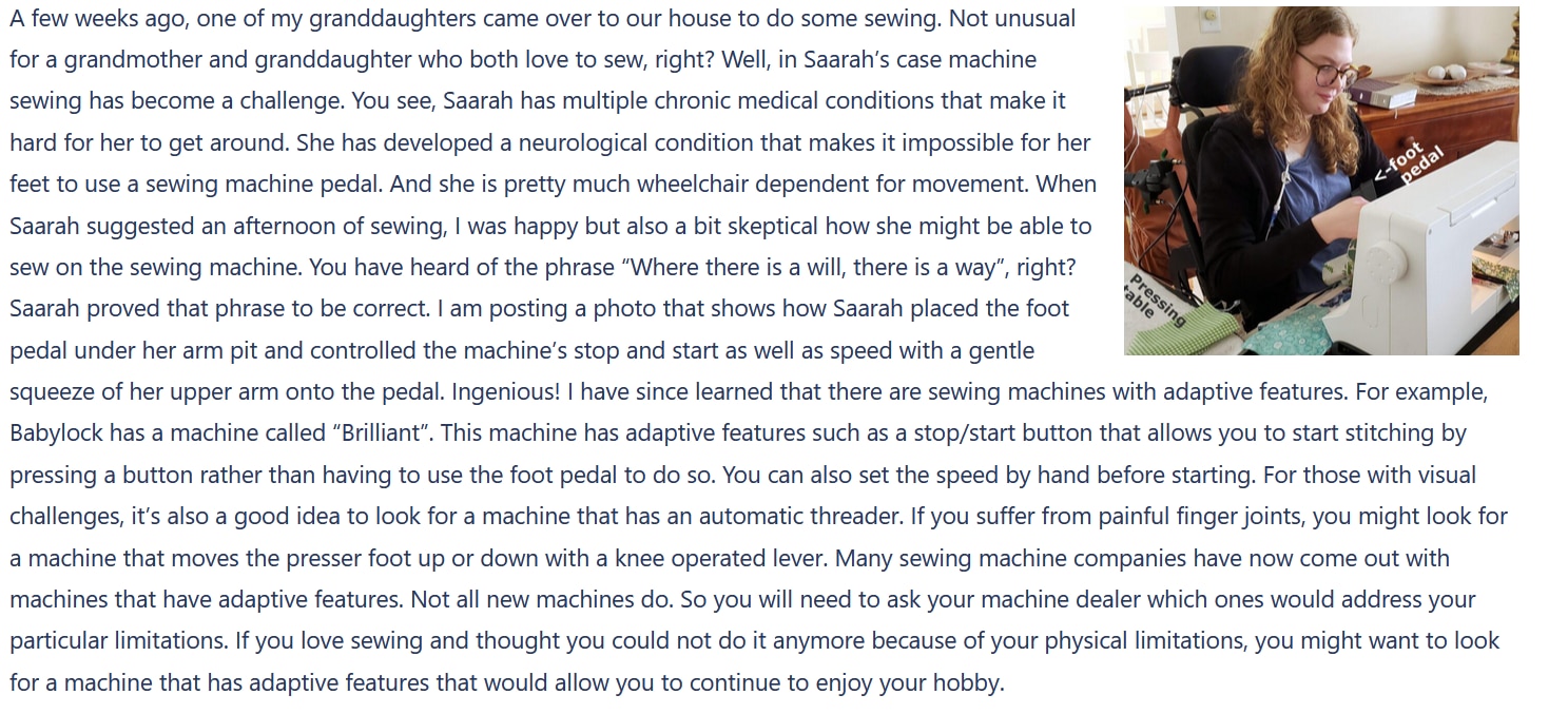
Making Process (Step by Step)
Step 1: Opening the Box & Experimenting with the Kit
After receiving the Kit my first work was to test the kit and understanding the features. The kit came with controller board named Landungsbrucke with the preloaded firmware that directly works with TMCL IDE. Both together make an excellent tool for testing and understanding the operation of the TMC5272 Trinamic motor controller. One of the interesting features was the capability of accessing all the registers of the TMC5272 motor controller. I understood several features of the controller board by reading and writing of the contents of the registers. I explain some of my experimentation and observation to my first blog here. I added the video again below for your quick reference.
Step 2: Interfacing with Arduino
In my project I needed to control the stepper motor very precisely based on the sensor. So, the motor needs to control by custom program or firmware. The Landungsbruecke board came with a preloaded firmware that is good for testing, experimenting and tuning of the motor driver but not for a custom application. For satisfying my requirement I intended to write my own code and run it in the ARM Cortex - M4 based GigaDevice GD32F425VGT6, the MCU of the Landungsbruecke board. I have no previous experiment on working with GigaDevice MCU. So, I wanted to develop and test the code in Arduino first before writing the code for GD32F425VGT6 MCU.
The TMC5272 Trinamic Motor Controller has an extensive datasheet and user manual. But writing a program by reading a device datasheet is very tedious and time consuming and requires advance understanding on both software and hardware. Rather it is always easy to start with a sample code without writing from scratch. Fortunately, TMC5272 has official C code for Arduino platform and supports both SPI and UART protocol. I downloaded the code from the GitHub and modified the code by removing unnecessary parts not related to my project.
The official sample code was written for Arduino MEGA and for avoiding any unnecessary confusion I wanted to test to code in Mega.
The TMC5272 motion controller supports both SPI and UART. The C code I downloaded implemented both the protocol. I connected an Arduino MEGA with the TMC5272 board following the configuration shown in the code. The connection is as follows:
|
Arduino Mega Pins
|
TMC5272 Eval Board Pins |
| 51 MOSI | 32 SPI1_SDI |
| 50 MISO | 33 SPI1_SDO |
| 52 SCK | 31 SPI1_SCK |
| 53 SS | 30 SPI1_CSN |
| GND | 23 CLK16 -> use internal |
| 23 DIO | 19 nSleep |
| GND | 2 GND |
| +5V | 5 +5V_USB |
| 27 iRefR2 | 35 IREF_R2 |
| 29 iRefR3 | 36 IREF_R3 |
| 31 uartMode | 20 USEL |
For initial testing I did not change any connection. The following photo shows my connection between Arduino and TMC5272 Eval board:

Running Motor in Velocity Mode
I directly uploaded the code provided by Analog Devices for the TMC5272 Motion Controller. The motor was started to rotate at a moderate speed and I was very happy to see because that happened without any difficulties. Watch the short video below:
Running in Position Mode
The demo code was written for driving the motor in velocity mode and in the video the motor is running in velocity mode. But for my project I need to control the motor in position mode and I want to control the TMC5272 using SPI. So, I removed all the code related to UART to make it clean. Then I made the necessary configuration on the code to drive the motor in position mode. I initialized the RAMPMODE register with zero for activating position mode as per the datasheet recommendation.

Then I set the maximum velocity and acceleration in VMAX and AMAX register respectively. I wrote the target position to M0_XTARGET register and expected to run the motor. But unfortunately it was not working. I read the related registers to understand what was the problem. The registers value was as expected.

I initialized the M0_VSTART and M0_VSTOP according to the datasheet but still not working. I set V1, V2, D1, D2 but nothing special was happening. So, I disconnected the TMC5272 Eval board from Arduino and connected to the Landungsbrucke board again for further understanding and monitoring all the related registers. Soon, I realized that I need to set a value for M0_DMAX register for running the motor in position mode. I again reconnect the Arduino board with the TMC5272 and set the DMAX value. The motor was running as expected. The code snippet for running the motor in position mode was follows:
initMotorOne(IC_ID);

  //tmc5272_rotateMotor(IC_ID, 0, 0x00005000);

  tmc5272_writeRegister(IC_ID, TMC5272_RAMPMODE, 0x0); //set position mode
  tmc5272_writeRegister(IC_ID, TMC5272_VSTART(0), 0); //set maximum valocity
  tmc5272_writeRegister(IC_ID, TMC5272_VSTOP(0), 10); //set maximum valocity
  tmc5272_writeRegister(IC_ID, TMC5272_TVMAX(0), 0); //disable jerk reduction
  tmc5272_writeRegister(IC_ID, TMC5272_AMAX(0), 50000); //set maximum acceleration
  tmc5272_writeRegister(IC_ID, TMC5272_VMAX(0), 100000); //set maximum valocity
  tmc5272_writeRegister(IC_ID, TMC5272_DMAX(0), 1000); //set maximum deacceleration
  tmc5272_writeRegister(IC_ID, TMC5272_D2(0), 1);
  tmc5272_writeRegister(IC_ID, TMC5272_XACTUAL(0), 0); //clear actual position
  tmc5272_writeRegister(IC_ID, TMC5272_XTARGET(0), 500000); //set a target position
  delay(10000);
  tmc5272_writeRegister(IC_ID, TMC5272_XTARGET(0), 0); //return to home position
The full Arduino code is as follows. In the code a target position is set. After reaching the target position it takes 10 seconds delay and returns to the initial position again. In the loop() function actual position and target position are printed repeatedly. Supporting library files are attached in the zip file.
/*******************************************************************************
* Copyright © 2023 Analog Devices Inc. All Rights Reserved.
* This software is proprietary to Analog Devices, Inc. and its licensors.
*******************************************************************************/

#include <SPI.h>

extern "C" {
#include "TMC5272_register_map.h"
#include "tmc5272.h"

}

/*
 * Arduino Pins   Eval Board Pins
 * 51 MOSI        32 SPI1_SDI
 * 50 MISO        33 SPI1_SDO
 * 52 SCK         31 SPI1_SCK
 * 53 SS          30 SPI1_CSN
 * GND            23 CLK16 -> use internal
 * 23 DIO         19 nSleep
 * GND            2 GND
 * +5V            5 +5V_USB
 * 27 iRefR2      35 IREF_R2
 * 29 iRefR3      36 IRREF_R3
 * 31 uartMode    20 USEL/ for uart mode it should be HIGH
 */

#define IC_ID 0

int nSleep = 23;
int iRefR2 = 27;
int iRefR3 = 29;
int uartMode = 31;

void tmc5272_readWriteSPI(uint16_t icID, uint8_t *data, size_t dataLength) {
  digitalWrite(PIN_SPI_SS, LOW);
  delayMicroseconds(10);

  for (uint32_t i = 0; i < dataLength; i++) {
    data[i] = SPI.transfer(data[i]);
    Serial.println(data[i]);
  }

  delayMicroseconds(10);
  digitalWrite(PIN_SPI_SS, HIGH);
}

void setup() {
  Serial.begin(115200);

  // put your setup code here, to run once:
  pinMode(PIN_SPI_SS, OUTPUT);
  pinMode(nSleep, OUTPUT);
  pinMode(iRefR2, OUTPUT);
  pinMode(iRefR3, OUTPUT);
  pinMode(uartMode, OUTPUT);

  digitalWrite(PIN_SPI_SS, HIGH);
  digitalWrite(nSleep, LOW); // Disabling standby
  digitalWrite(iRefR2, LOW);
  digitalWrite(iRefR3, LOW);


  digitalWrite(uartMode, LOW);
  SPI.begin();
  SPI.beginTransaction(SPISettings(500000, MSBFIRST, SPI_MODE3));

  delay(10);

  //set resistance to 10K
  digitalWrite(iRefR2, HIGH);
  digitalWrite(iRefR3, HIGH);

  initMotorOne(IC_ID);

  //tmc5272_rotateMotor(IC_ID, 0, 0x00005000);

  tmc5272_writeRegister(IC_ID, TMC5272_RAMPMODE, 0x0); //set position mode
  tmc5272_writeRegister(IC_ID, TMC5272_VSTART(0), 0); //set maximum valocity
  tmc5272_writeRegister(IC_ID, TMC5272_VSTOP(0), 10); //set maximum valocity
  tmc5272_writeRegister(IC_ID, TMC5272_TVMAX(0), 0); //disable jerk reduction
  tmc5272_writeRegister(IC_ID, TMC5272_AMAX(0), 50000); //set maximum acceleration
  tmc5272_writeRegister(IC_ID, TMC5272_VMAX(0), 100000); //set maximum valocity
  tmc5272_writeRegister(IC_ID, TMC5272_DMAX(0), 1000); //set maximum deacceleration
  tmc5272_writeRegister(IC_ID, TMC5272_D2(0), 1);
  tmc5272_writeRegister(IC_ID, TMC5272_XACTUAL(0), 0); //clear actual position
  tmc5272_writeRegister(IC_ID, TMC5272_XTARGET(0), 500000); //set a target position
  delay(10000);
  tmc5272_writeRegister(IC_ID, TMC5272_XTARGET(0), 0); //return to home position
}

void loop() {

  int32_t value1 = tmc5272_readRegister(IC_ID, TMC5272_XACTUAL(0));
  int32_t value2 = tmc5272_readRegister(IC_ID, TMC5272_XTARGET(0));

  Serial.print("Received Data: ");
  Serial.print(value1);
  Serial.print("  ");
  Serial.println(value1);

  Serial.print(" from register: ");
  Serial.print(TMC5272_XTARGET(0), HEX);
  Serial.print("  ");
  Serial.println(TMC5272_XTARGET(0), HEX);
  delay(1000);

}
See the position mode demo video below for the above code:
I explain the working of Arduino Mega with the Trinamic Motor Controller in my second blog here.
Step 3: Implementing StallGuard using Arduino
I worked with different types of stepper motors and stepper motors controller before but I was not aware of about the StallGuard and CoolStep features. While I was reading the the TMC5272 datasheet I came to know those features for the first time. For better understanding of the features I search in Google and found several tutorial from Analog Devices and I added the link in the reference section. Also I found the following video from the Analog Devices YouTube that was very interesting for me.
Soon I realized the power of the StallGuard and coolStep and understand that using StallGuard can reduce the use of limit switch in my project. I explored this features from the TMC IDE. TMC IDE offers tuning and testing StallGuard and CoolStep very effectively and we can take advantage from it during custom firmware design for MCU for controlling TMC5272 like stepper controllers.
Several registers of TMC5272 are involved with StallGuard and CoolStep and we need to programmatically control those registers from MCU. As I was working with the Arduino I was curious to implement this using Arduino and with the help of TMC IDE and the TMC5272 datasheet I was able to successfully implement StallGuard and CoolStep from Arduino. From the datasheet I discovered that SW_MODE register is responsible to enable the StallGuard and we can check the status from the RAMP_STAT register which is very important for taking any discission based on StallGuard.


Above mages are captured from TMC5272 datasheet. The sg_stop bit of SW_MODE register is responsible for enabling or disabling of StallGuard2 or 4.
This is the sample test code I wrote for Arduino for controlling StallGuard.
/*******************************************************************************
* Copyright © 2023 Analog Devices Inc. All Rights Reserved.
* This software is proprietary to Analog Devices, Inc. and its licensors.
*******************************************************************************/

#include <SPI.h>

extern "C" {
#include "TMC5272_register_map.h"
#include "tmc5272.h"

}

/*
 * Arduino Pins   Eval Board Pins
 * 51 MOSI        32 SPI1_SDI
 * 50 MISO        33 SPI1_SDO
 * 52 SCK         31 SPI1_SCK
 * 53 SS          30 SPI1_CSN
 * GND            23 CLK16 -> use internal
 * 23 DIO         19 nSleep
 * GND            2 GND
 * +5V            5 +5V_USB
 * 27 iRefR2      35 IREF_R2
 * 29 iRefR3      36 IRREF_R3
 * 31 uartMode    20 USEL/ for uart mode it should be HIGH
 */

#define IC_ID 0

int nSleep = 23;
int iRefR2 = 27;
int iRefR3 = 29;
int uartMode = 31;

void tmc5272_readWriteSPI(uint16_t icID, uint8_t *data, size_t dataLength) {
  digitalWrite(PIN_SPI_SS, LOW);
  delayMicroseconds(10);

  for (uint32_t i = 0; i < dataLength; i++) {
    data[i] = SPI.transfer(data[i]);
    Serial.println(data[i]);
  }

  delayMicroseconds(10);
  digitalWrite(PIN_SPI_SS, HIGH);
}

void setup() {
  Serial.begin(115200);

  // put your setup code here, to run once:
  pinMode(PIN_SPI_SS, OUTPUT);
  pinMode(nSleep, OUTPUT);
  pinMode(iRefR2, OUTPUT);
  pinMode(iRefR3, OUTPUT);
  pinMode(uartMode, OUTPUT);

  digitalWrite(PIN_SPI_SS, HIGH);
  digitalWrite(nSleep, LOW); // Disabling standby
  digitalWrite(iRefR2, LOW);
  digitalWrite(iRefR3, LOW);


  digitalWrite(uartMode, LOW);
  SPI.begin();
  SPI.beginTransaction(SPISettings(500000, MSBFIRST, SPI_MODE3));

  delay(10);

  //set resistance to 10K
  digitalWrite(iRefR2, HIGH);
  digitalWrite(iRefR3, HIGH);

  initMotorOne(IC_ID);

  //tmc5272_rotateMotor(IC_ID, 0, 0x00005000);

  tmc5272_writeRegister(IC_ID, TMC5272_TPWMTHRS(0), 0x1500000); //this is the upper velocity for StealthChop2 voltage PWM mode, ST2 is enable if TSTEP>=TPWMTHRS
  tmc5272_writeRegister(IC_ID, TMC5272_TCOOLTHRS(0), 0x50000);//lower velocity threshold for switching CoolStep and StallGuard2/4 features, enable if TCOOLTHRS >= TSTEP
  tmc5272_writeRegister(IC_ID, TMC5272_THIGH(0), 0x0);//upper velocity threshold for switching CoolStep, disabled if TSTEP <= THIGH
  tmc5272_writeRegister(IC_ID, TMC5272_SG4_THRS(0), 30); //stall detection threshold
  //tmc5272_writeRegister(IC_ID, TMC5272_SW_MODE(0), 0x0);
  field_write(IC_ID, TMC5272_SW_MODE_SG_STOP_FIELD(0), 1); //enable stop by StallGuard2/4

  tmc5272_writeRegister(IC_ID, TMC5272_RAMPMODE, 0x0); //set position mode
  tmc5272_writeRegister(IC_ID, TMC5272_VSTART(0), 0); //set maximum valocity
  tmc5272_writeRegister(IC_ID, TMC5272_VSTOP(0), 10); //set maximum valocity
  tmc5272_writeRegister(IC_ID, TMC5272_TVMAX(0), 0); //disable jerk reduction
  tmc5272_writeRegister(IC_ID, TMC5272_AMAX(0), 50000); //set maximum acceleration
  tmc5272_writeRegister(IC_ID, TMC5272_VMAX(0), 100000); //set maximum valocity
  tmc5272_writeRegister(IC_ID, TMC5272_DMAX(0), 1000); //set maximum deacceleration
  tmc5272_writeRegister(IC_ID, TMC5272_D2(0), 1);
  tmc5272_writeRegister(IC_ID, TMC5272_XACTUAL(0), 0); //clear actual position
  tmc5272_writeRegister(IC_ID, TMC5272_XTARGET(0), 500000); //set a target position
  delay(10000);
  field_write(IC_ID, TMC5272_RAMP_STAT_STATUS_SG_FIELD(0), 0); //disable stop by StallGuard2/4
  field_write(IC_ID, TMC5272_SW_MODE_SG_STOP_FIELD(0), 0); //disable stop by StallGuard2/4
  tmc5272_writeRegister(IC_ID, TMC5272_XTARGET(0), 0); //return to home position
}

void loop() {

  int32_t value1 = tmc5272_readRegister(IC_ID, TMC5272_RAMP_STAT(0));
  int32_t value2 = tmc5272_readRegister(IC_ID, TMC5272_SG4_THRS(0));

  Serial.print("Received Data: ");
  Serial.print(value1, HEX);
  Serial.print("  ");
  Serial.println(value1);

}
I added some helpful comments in the code which can help you to easily understand the code and operation. In the code the driver is configure to drive the stepper motor in position mode. A target position is set to XTRAGT register. Motor moves clockwise to achieve the position and the StallGuard is enable in this journey. After reaching the target a 10s pause is set. The motor returns to home position again and this time the StallGuard is disable.
This is the demo video of the action of the above code:
Step 4: 3D Printing & Assembly
As I was determined to make a plug and play solution so that the project helps to control sewing machine by hand without modifying anything in the machine, I realized the necessity of 3D printed model. I spent some time on think the easiest solution and finally I was able to design a simple, compact and workable model. Generally sewing machine uses foot pedal for controlling and users use their foot and press on the pedal. So, we need to replicate the press of human foot I developed a 3D printed vertical mechanism for pressing the foot pedal down based on the hand finger bending. I used the following components for the pressing mechanism.
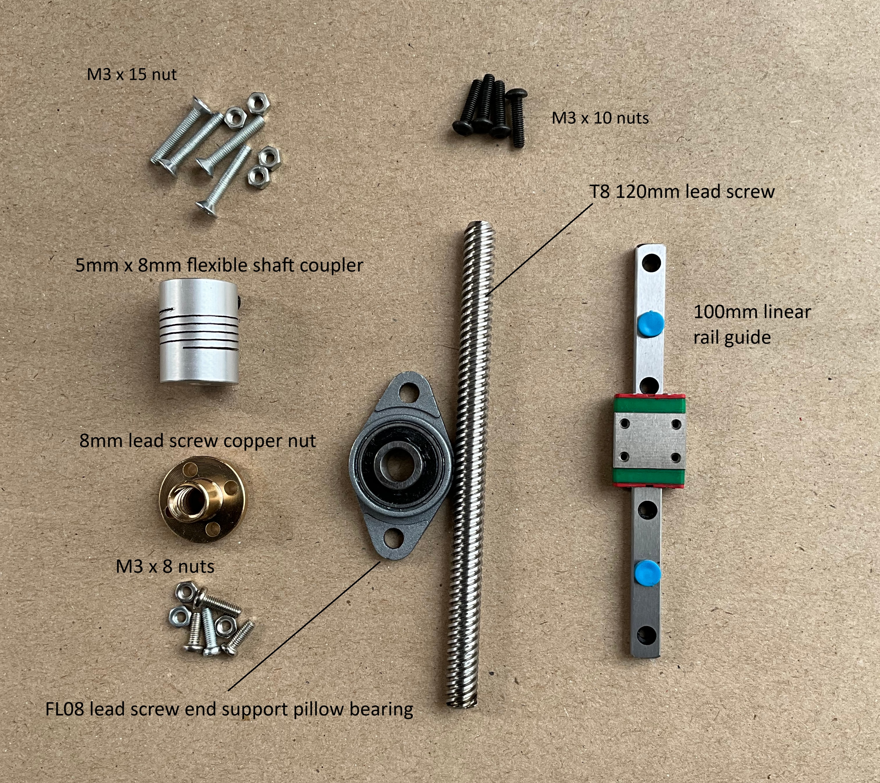
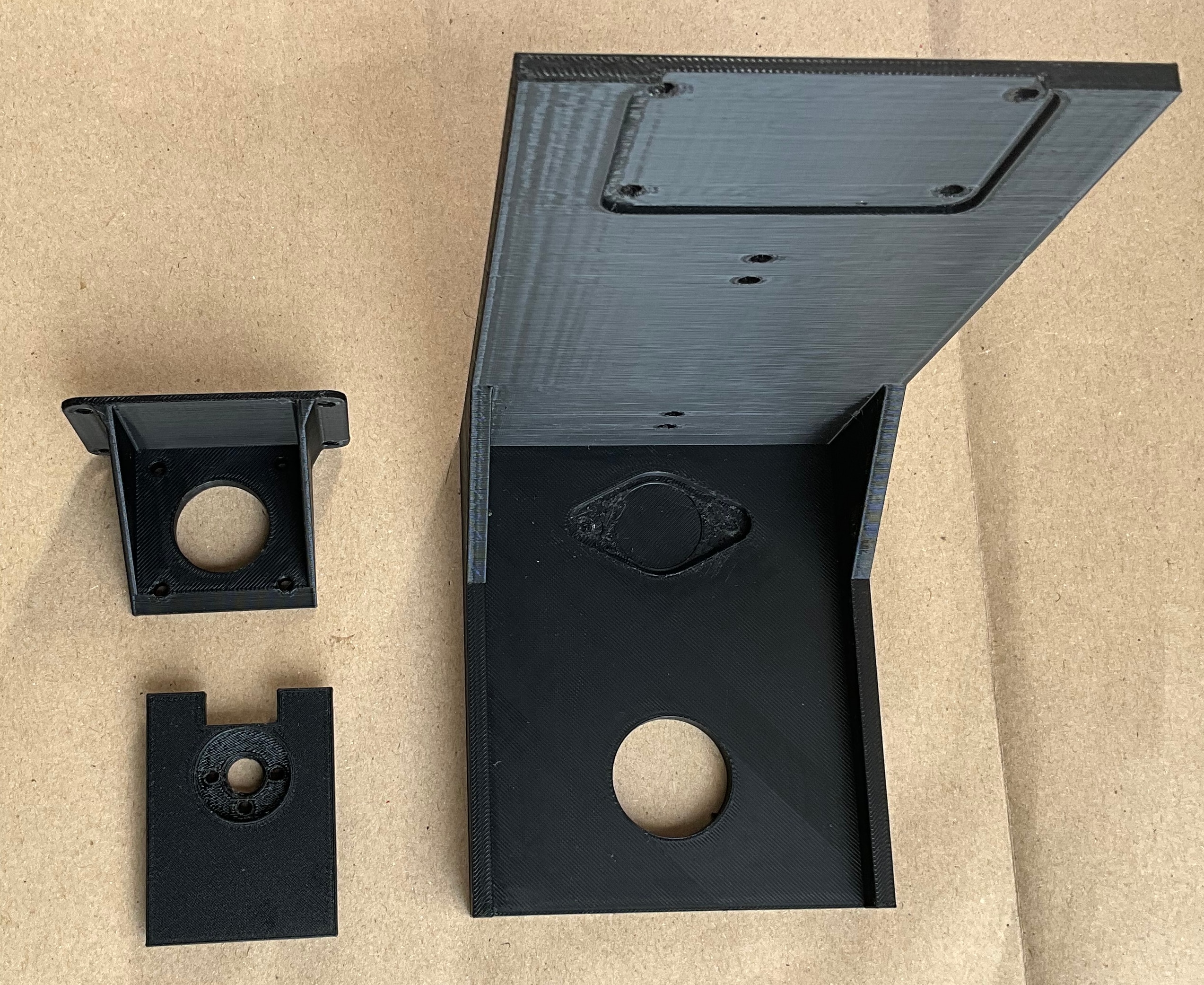
I added the links of the main components in the reference section. I designed and 3D printed the following parts. The .stl design files are attached in the attachment section. The left top is the stepper mount, the left bottom is the armature and the right big part is the base.
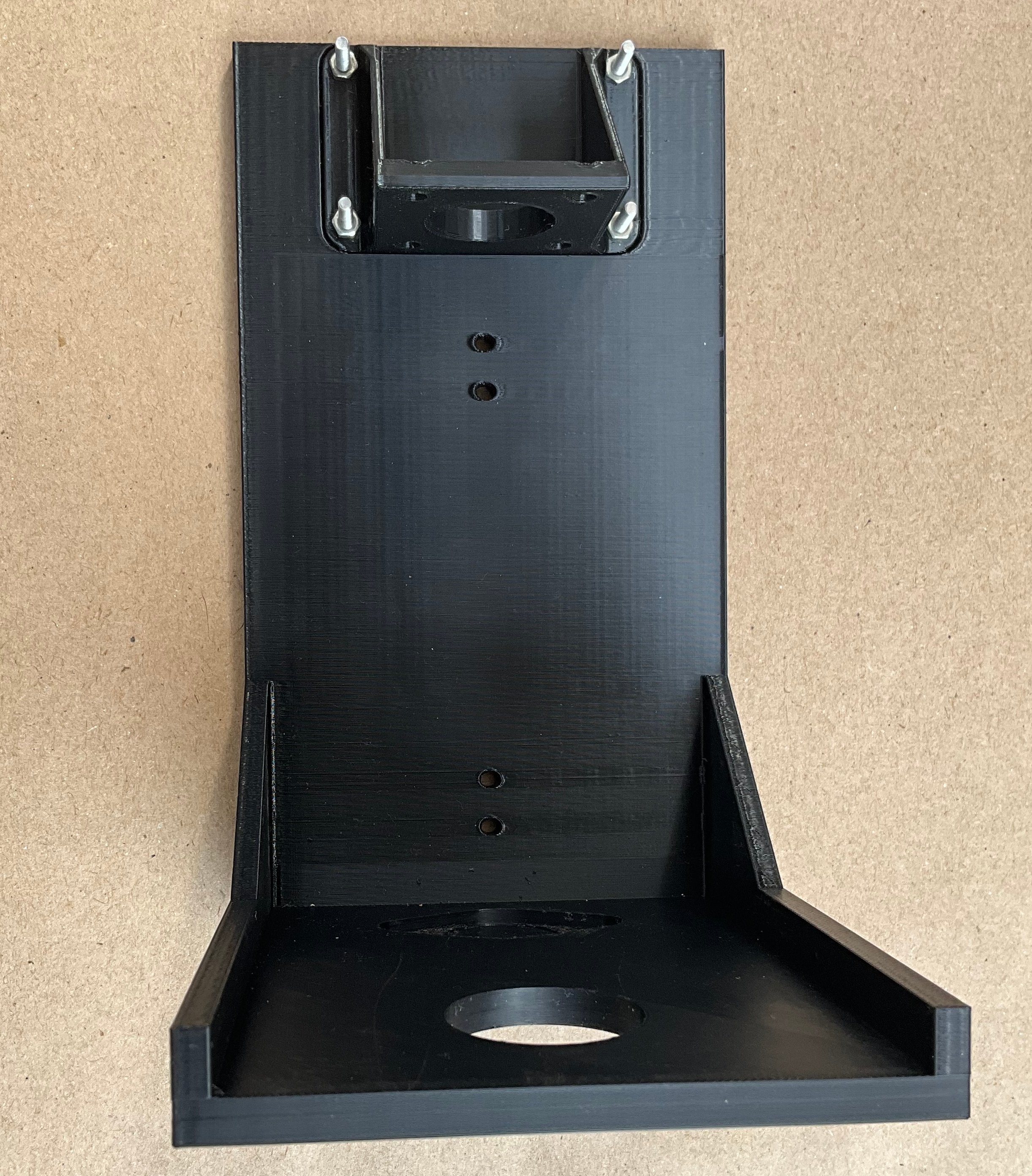
The following image shows the assembly of the stepper mount with the base using 4 M3x15 screws.
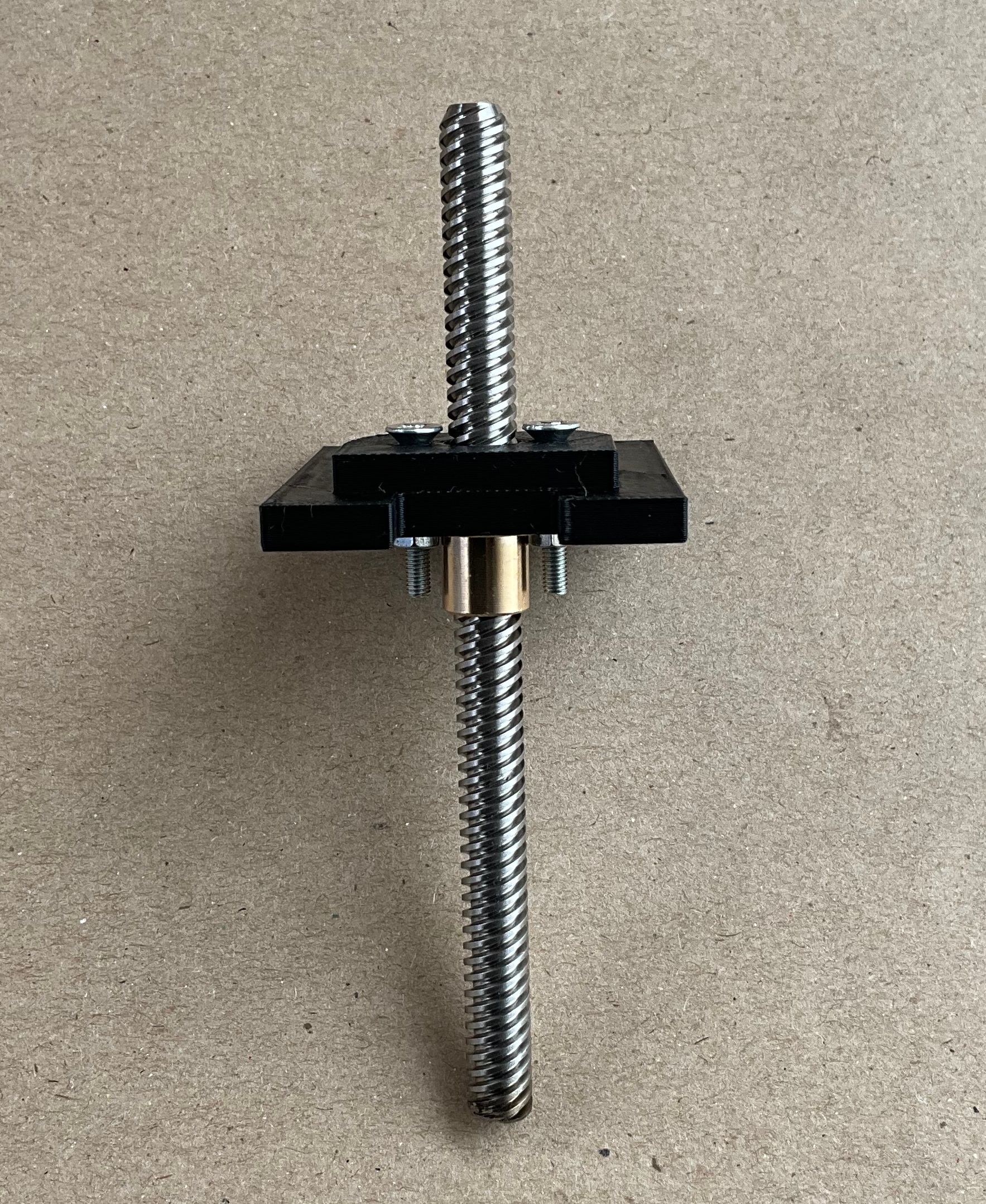
The assembly of the armature with the threaded rod and screw is shown in the following images.
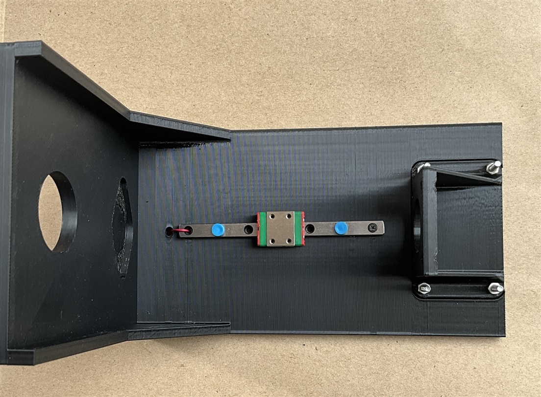
The following photo shows installing the linear rail that helps to smoothly guide the armature vertically up and down.
The complete assembled pressing mechanism is shown in the following images.
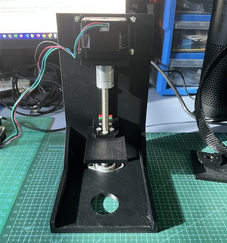
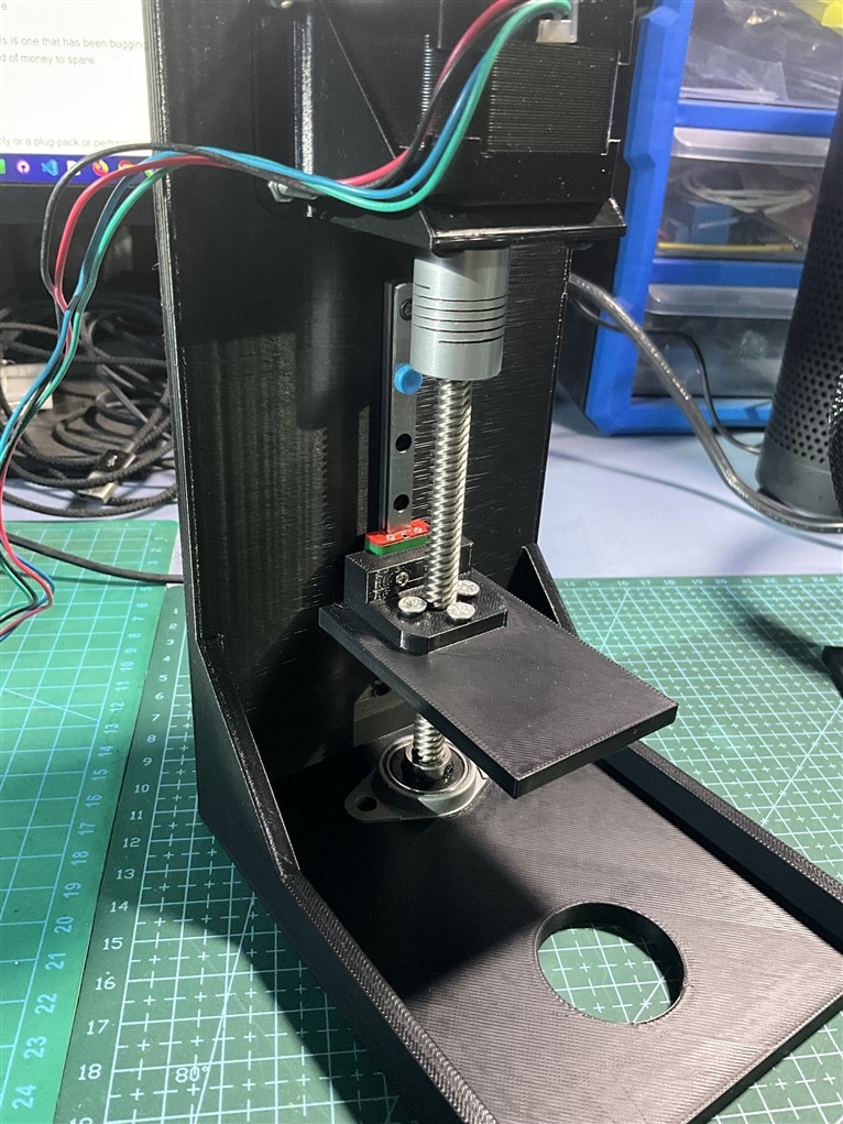
You can watch the working video below:
Step 5: Adding Flex Sensor
I am going to use a Flex sensor to control the stepper motor based on the bending of the finger. A flex sensor is a low-cost, easy-to-use variable resistor that is designed to measure the amount of deflection it experiences when bent. The sensor's resistance is lowest when it's straight or flat on the surface, increases when we bend it slowly and reaches its maximum when it's at a 90-degree angle. Due to it's size a flex sensor can be easily attached with the finger to measure the bending of the finger.
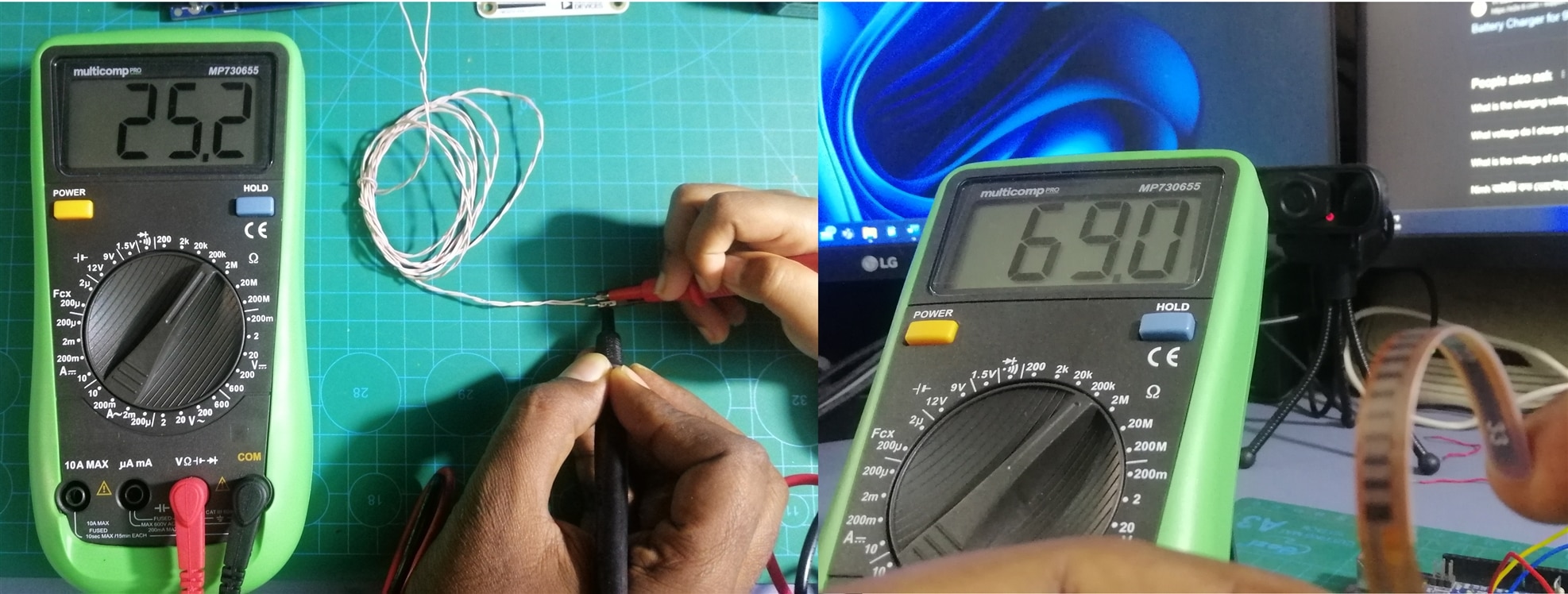
As already said, a flex sensor is a variable resistor that varies its resistance upon bending. As the resistance of the sensor is directly proportional to the amount of bending, it's often called Flexible potentiometer. This sensor is commonly available in two sizes, the first is 2.2” and the second one is 4.5” long. I am using the 2.2 inch flex for my project. When the sensor is straight the resistance is about 25K, and when the sensor is bent the value is 69K. As flex sensor is a resistor we must convert the resistance to voltage to read it using MCU. To get a proportional voltage to the sensor we need to make a voltage divider circuit attaching a fixed resistor in series with the sensor as shown in the animated image below. Based on the bending the resistance of the sensor changes and the output voltage also changes accordingly.
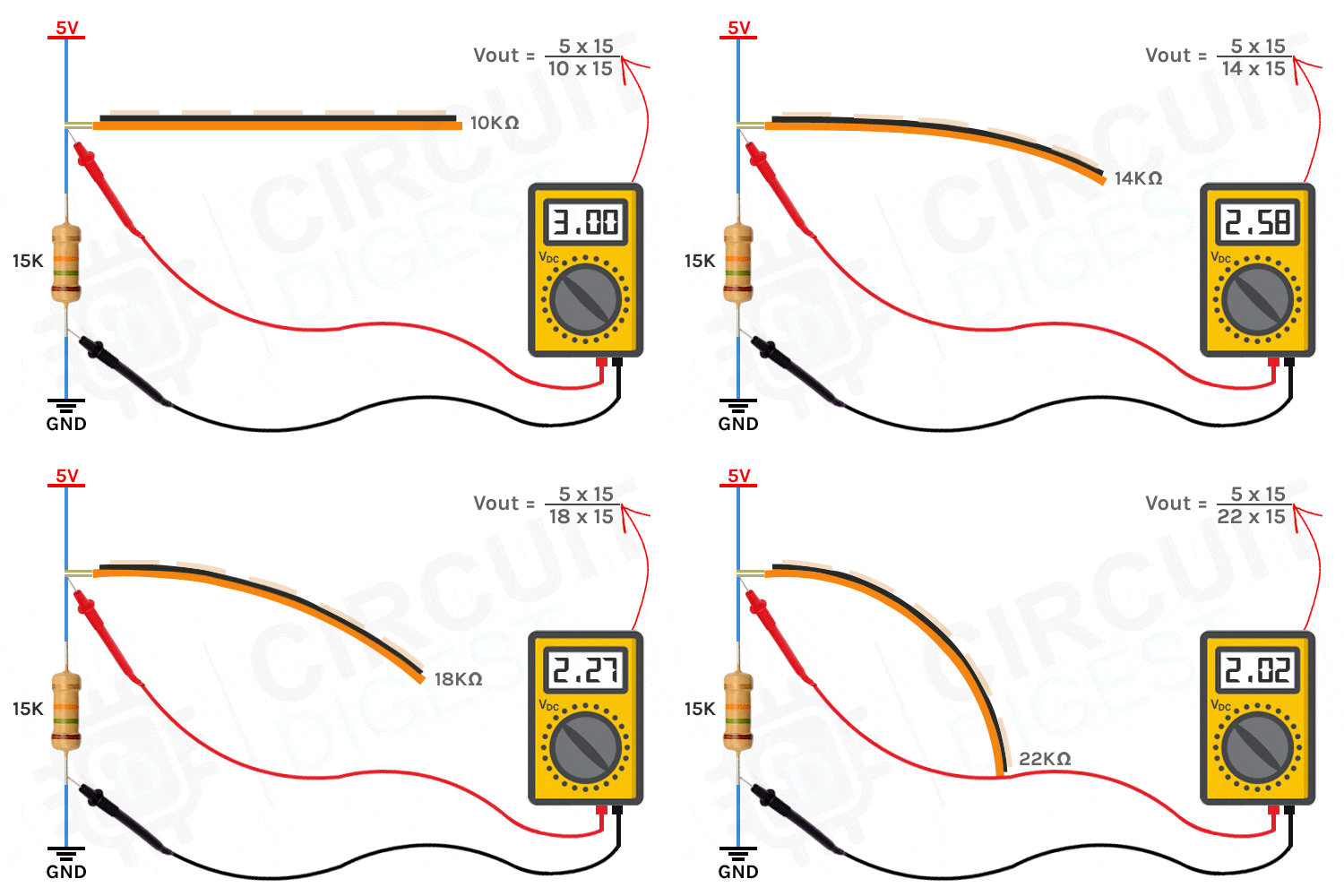
The image was taken from circuitdigest.com
The sensitivity of the sensor depends on the value of the fixed resistor connected with the flex sensor. For calculating the exact value for maximum sensitivity first I measured the resistance of the sensor when it is straight and when it is bent at 90 degree. Then I calculate the resistance for getting the maximum variation in the output volage using Microsoft Excel.


I got the maximum sensitivity for the resistance of 41.5K. So, I planned to placed a 50K trim pot and set it to 41.5K and then connect it in series with the Flex sensor to get the maximum sensitivity. But for testing I connected one 20K and one 22K resistor in series for getting an approximate output. I used the following code for running the motor based on the bending.
/*******************************************************************************
* Copyright © 2023 Analog Devices Inc. All Rights Reserved.
* This software is proprietary to Analog Devices, Inc. and its licensors.
*******************************************************************************/

#include <SPI.h>

extern "C" {
#include "TMC5272_register_map.h"
#include "tmc5272.h"

}

/*
 * Arduino Pins   Eval Board Pins
 * 51 MOSI        32 SPI1_SDI
 * 50 MISO        33 SPI1_SDO
 * 52 SCK         31 SPI1_SCK
 * 53 SS          30 SPI1_CSN
 * GND            23 CLK16 -> use internal
 * 23 DIO         19 nSleep
 * GND            2 GND
 * +5V            5 +5V_USB
 * 27 iRefR2      35 IREF_R2
 * 29 iRefR3      36 IRREF_R3
 * 31 uartMode    20 USEL/ for uart mode it should be HIGH
 */

#define IC_ID 0

int nSleep = 23;
int iRefR2 = 27;
int iRefR3 = 29;
int uartMode = 31;

void tmc5272_readWriteSPI(uint16_t icID, uint8_t *data, size_t dataLength) {
  digitalWrite(PIN_SPI_SS, LOW);
  delayMicroseconds(10);

  for (uint32_t i = 0; i < dataLength; i++) {
    data[i] = SPI.transfer(data[i]);
    Serial.println(data[i]);
  }

  delayMicroseconds(10);
  digitalWrite(PIN_SPI_SS, HIGH);
}
int previous_value;
void setup() {
  Serial.begin(115200);

  // put your setup code here, to run once:
  pinMode(PIN_SPI_SS, OUTPUT);
  pinMode(nSleep, OUTPUT);
  pinMode(iRefR2, OUTPUT);
  pinMode(iRefR3, OUTPUT);
  pinMode(uartMode, OUTPUT);

  digitalWrite(PIN_SPI_SS, HIGH);
  digitalWrite(nSleep, LOW); // Disabling standby
  digitalWrite(iRefR2, LOW);
  digitalWrite(iRefR3, LOW);


  digitalWrite(uartMode, LOW);
  SPI.begin();
  SPI.beginTransaction(SPISettings(500000, MSBFIRST, SPI_MODE3));

  delay(10);

  //set resistance to 10K
  digitalWrite(iRefR2, HIGH);
  digitalWrite(iRefR3, HIGH);


  initMotorOne(IC_ID);

  tmc5272_writeRegister(IC_ID, TMC5272_RAMPMODE, 0x0); //set position mode
  tmc5272_writeRegister(IC_ID, TMC5272_VSTART(0), 0); //set maximum valocity
  tmc5272_writeRegister(IC_ID, TMC5272_VSTOP(0), 10); //set maximum valocity
  tmc5272_writeRegister(IC_ID, TMC5272_TVMAX(0), 0); //disable jerk reduction
  tmc5272_writeRegister(IC_ID, TMC5272_AMAX(0), 50000); //set maximum acceleration
  tmc5272_writeRegister(IC_ID, TMC5272_VMAX(0), 100000); //set maximum valocity
  tmc5272_writeRegister(IC_ID, TMC5272_DMAX(0), 1000); //set maximum deacceleration
  tmc5272_writeRegister(IC_ID, TMC5272_D2(0), 1);
  tmc5272_writeRegister(IC_ID, TMC5272_XACTUAL(0), 0); //clear actual position

  previous_value = analogRead(A0);
}


void loop() {

  int sensor_value = analogRead(A0);
  int diff = abs(sensor_value - previous_value);
  if(diff>30)
    tmc5272_writeRegister(IC_ID, TMC5272_XTARGET(0), sensor_value*10000); //set a target position
  previous_value = sensor_value;
  Serial.println(sensor_value);
  delay(15);

}
After uploading the above code I got the following result:
Step 6: Adjusting Torque and Current Rating
After making the linear pressing system with the 3D printed parts and stepper motor I was curious to check it with the foot pedal of the sewing machine. The pedal is not very easy to press and it requires a moderate amount of pressure to operate. It can be comfortably done with the foot but I was a bit afraid of whether my pressing mechanism is capable of moving it down or not. For checking it I placed the foot pedal at the bottom of the armature and started the motor. I was disappointed, it stops when the armature touches the pedal. After thinking for a few moments I got the idea of increasing the supply voltage. I removed the power adapter and connected a power supply to the TMC5272 controller board. I set the voltage to 12V and observed the current and it was only around 60mA while running the motor. I increased the voltage to 20V and this time motor was capable of pressing down the foot pedal as shown in the video below.
Though it worked I was not convinced to do it by increasing the voltage. I wanted to make it workable with 12V because the challenger kit includes a 12V power supply. So, I started reading the TM5272 datasheet again to find out whether it has any solution. The article "Setting the Full-Scale Current" on page 54 drew my attention. I got an equation for the RMS and Peak current.


I came to know that by configuring the DRV_CONF register we can set the 100% current or less and the default current setting is not 100%. From the table 14 and 15, I found the required value for the DRV_CONF register for an expected current. I revisited the code and found that the content for four LSB bits is D (1101) which means FSR_Mx bits are 01 and FSR_IREF_Mx bits are 11 which allows a maximum 410mA for the motor. It should work but not!

Possibly the current was not bad for pressing the pedal but it was not working for any reason. I changed the contents of the DRV_CONF register and replaced D with F. F will allow maximum current (800mA) to the motor. I added the marked line in my main code inside the setup function with other configurations to write the value to the DRV_CONF register.

Surprisingly it worked and this time motor was capable of pressing the pedal very easily even from an 8V supply. Current flowing was also increased reasonably.
Watch the video below:
Step 7: Changing the Microcontroller
When I started this project I decided to use Landungsbrucke finally which came with the kit as the main controller of my project. I intended to write custom firmware to read the sensor and control the stepper motor accordingly. The Landungsbrucke board came with preloaded firmware that helps to control the TMC5272 Motor Controller board from TMCL IDE. This is an excellent way for testing and debugging. The most interesting fact is you can monitor and modify all the registers from the IDE. It helped me to clearly understand some of the functionalities of the TMC5272 motor controller. The Landungsbrucke MCU board is based on the GigaDevice Arm Cortex M4 microcontroller and I have no previous experience with GigaDevice MCU. So, I started with Arduino Mega. I was able to write and run the code without any issues and it worked successfully. However, I faced some difficulties while modifying the code and I was able to successfully solve the issues with the help of TMC IDE. After solving the issues I decided to implement the code in GigaDevice Arm Cortex M4 microcontroller. I downloaded the Keil IDE and the required Add-ons for the Keil IDE for GigaDevice. I also downloaded the source code of the pre-loaded firmware.

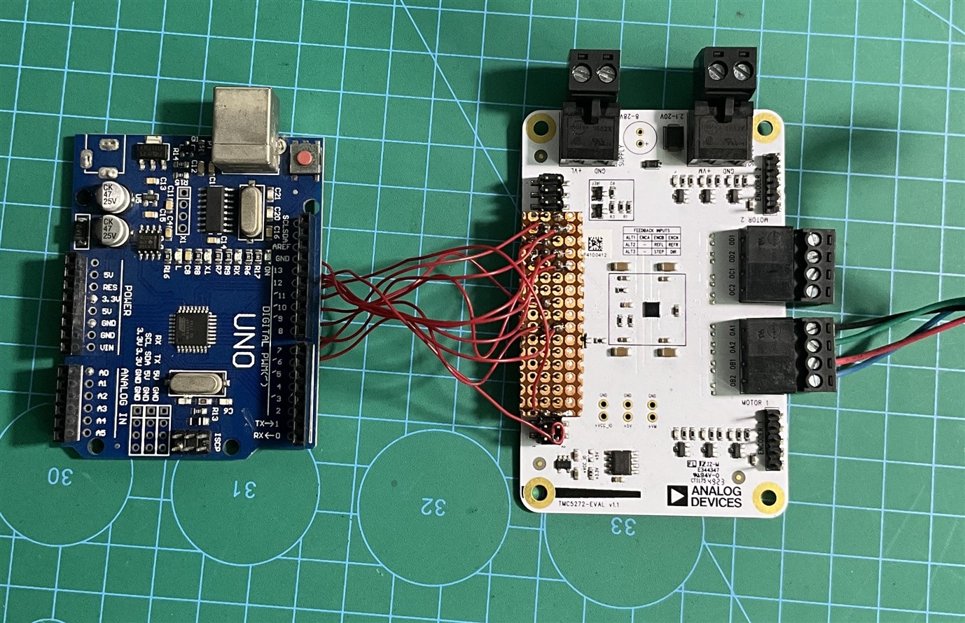
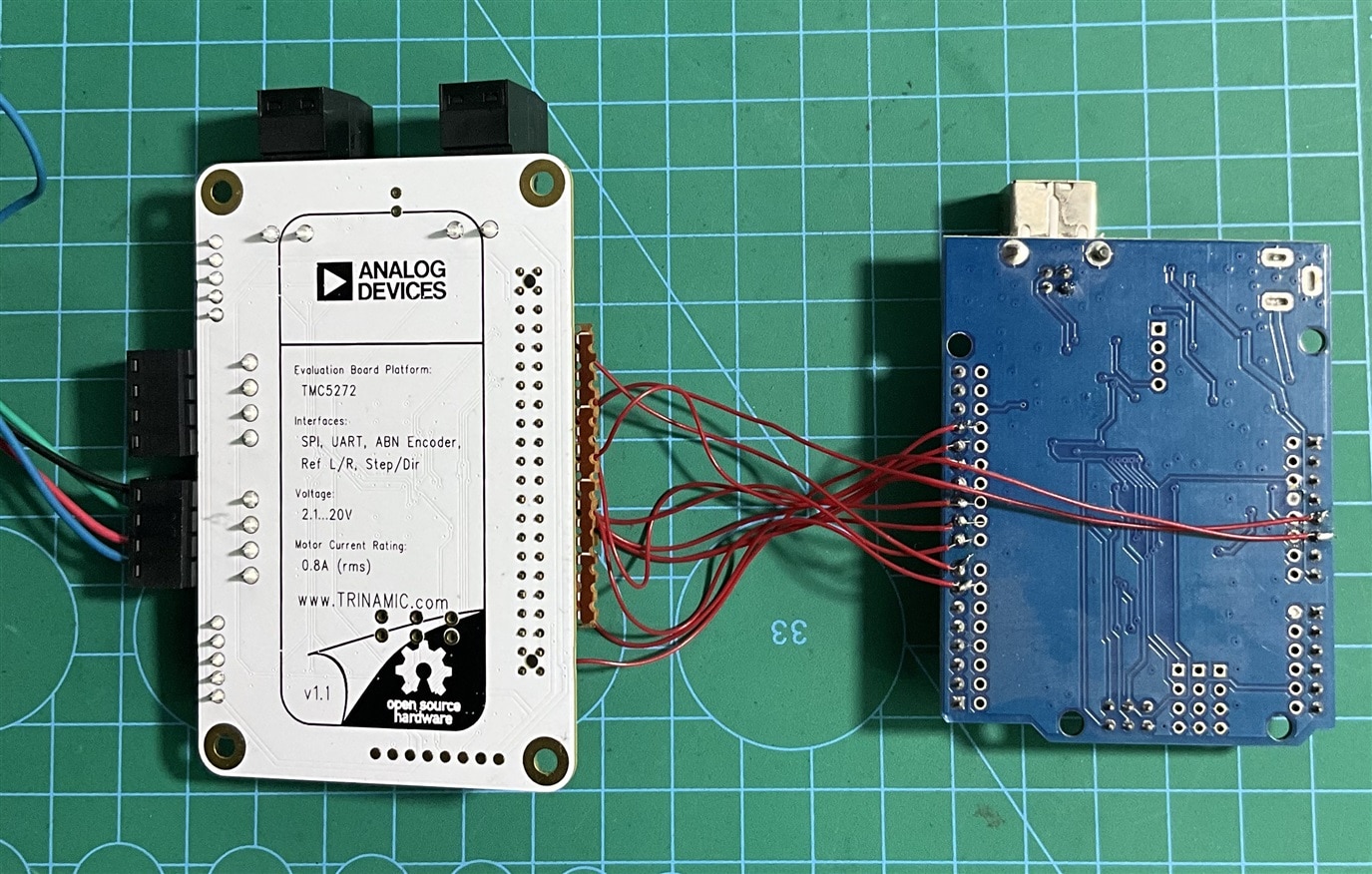
After a few hours of study and experiment, I realized it would be tough for me to implement the GigaDevice MCU within the limited time (I had only 6 days only before the deadline). Even I don't have any GD-Link programmers and I am not sure whether ST-Link will work with the GigaDevice MCU or not. So, I changed my mind and decided to use Arduino UNO in my project. I removed all the connections with the Mega and inserted a double-line male pin header into the connector of the TMC5272 and then soldered with the Arduino UNO with jumper wires as shown in the images below. Adding the small Perf board helped me to easily solder the jumper wires and it also made the connections strong.
In the Arduino side I directly soldered the jumper wires with the Arduino female pin headers using some extra solder. I changed the pin connection as the following table:
| TMC5272 Eval Board Pin | Arduino Uno Pin |
|
32 SPI1_SDI
|
11 MOSI |
|
33 SPI1_SDO
|
12 MISO |
|
31 SPI1_SCK
|
13 SCK |
|
30 SPI1_CSN
|
10 SS |
|
23 CLK16 -> use internal
|
GND |
|
19 nSleep
|
9 Digital pin |
|
2 GND
|
GND |
|
5 +5V_USB
|
5V |
|
35 IREF_R2
|
8 Digital pin |
|
36 IREF_R3
|
7 Digital pin |
|
20 USEL
|
6 Digital pin |
I made the necessary pin change in my code and uploaded the code to Arduino UNO. It worked as expected.

Step 8: Working with the Sensor
As I am using a flex sensor for detecting the bending of the finger to control the foot pedal I need to precisely read the flex and at the same time I need to wear it in such a way that it can be easily bent and make straight. A flex sensor is a variable resistor and we need to convert the resistor value to a proportional voltage output to read it using a microcontroller. We usually make a voltage divider circuit to get proportional voltage from the sensor. I already calculated the value of the series resistor to get maximum sensitivity from the flex sensor. The value was around 42K and I connected one 20K and one 22K resistors in series to get 42K resistance. The sensor connection is shown in the image below.


Without using any external PCB I directly soldered the resistors and flex sensor's terminal to the Arduino board as shown in the image above.
I added a long flexible wire to the flex sensor so that it can be bent from a distance. The flex sensor will be worn on a finger and the sensor should be easily bent and straight without any issue. To make the process stable and comfortable I designed two 3D printed rings with small holes for the sensor. The bigger ring will be worn first and the sensor's lead side is tightly attached to the ring using two screws.

The wearing process of the sensor is shown in the following images. The sensor can move easily inside the top ring but it can not get out from the ring.
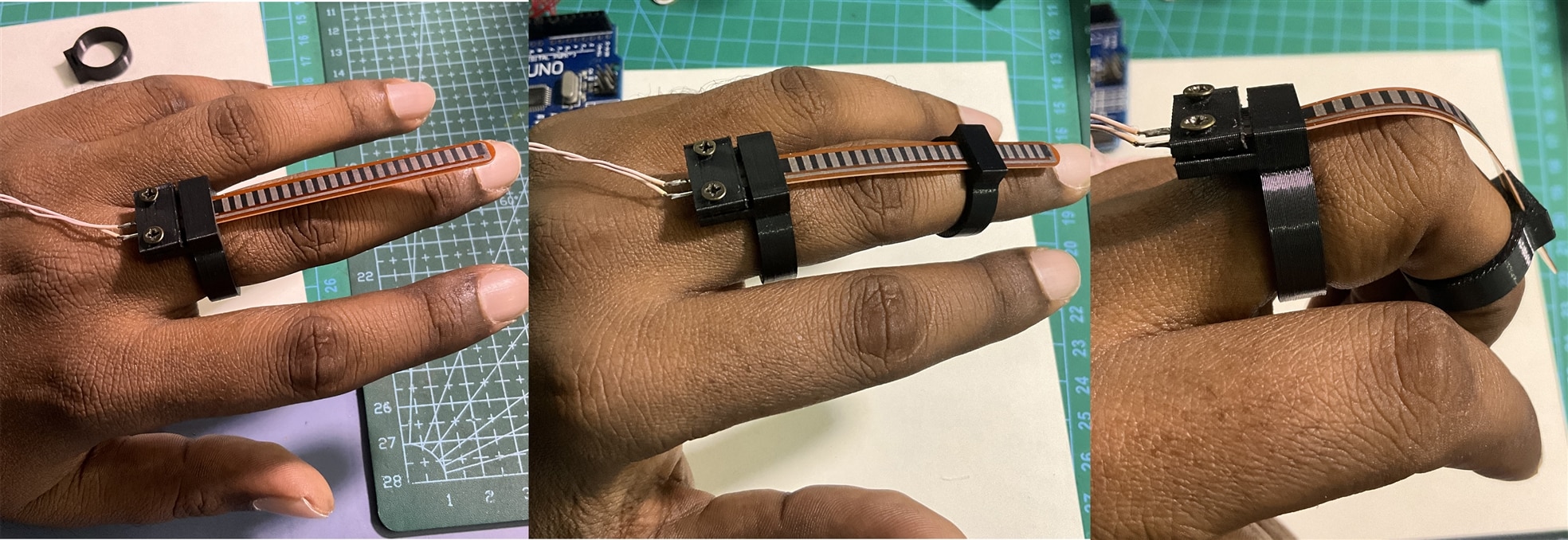


The video in action:
The Final Step: Finalizing the Code and Final Assembly
After finishing the testing parts I compiled all the code snippet and make my final Arduino code. The final code is below. Complete code with the library files are attached at the end of this project tutorial.
Arduino Code
/*******************************************************************************
* Copyright © 2023 Analog Devices Inc. All Rights Reserved.
* This software is proprietary to Analog Devices, Inc. and its licensors.

The original code is modified to control the stepper motor for controlling the foot
pedal of a sewing machine base on the finger bending.

Author: Md. Khairul Alam
Date: 4 January, 2025


*******************************************************************************/

#include <SPI.h>

extern "C" {
#include "TMC5272_register_map.h"
#include "tmc5272.h"

}

//Pin connections between TMC5272 Motor Controller and Arduino UNO
/*
 * Eval Board Pins            Arduino UNO Pins
 * 32 SPI1_SDI                   11     MOSI
 * 33 SPI1_SDO                   12     MISO
 * 31 SPI1_SCK                   13     SCK
 * 30 SPI1_CSN                   10     SS
 * 23 CLK16 -> use internal      GND    GND
 * 19 nSleep                     9      Digital
 * 2 GND                         GND    GND
 * 5 +5V_USB                     5V     5V
 * 35 IREF_R2                    8      Digital (iRefR2)
 * 36 IRREF_R3                   7      Digital (iRefR3)
 * 20 USEL                       6      Digital (uartMode)
 */

#define IC_ID 0

///Pin declaration
int nSleep = 9;
int iRefR2 = 8;
int iRefR3 = 7;
int uartMode = 6;


//Variables
int sensor_value = analogRead(A0);
int previous_value = sensor_value;
int change = 0;
long position = 0;
long offset;
int stallStatus;


//User defined functions
void tmc5272_readWriteSPI(uint16_t icID, uint8_t *data, size_t dataLength) {
  digitalWrite(PIN_SPI_SS, LOW);
  delayMicroseconds(10);

  for (uint32_t i = 0; i < dataLength; i++) {
    data[i] = SPI.transfer(data[i]);
    Serial.println(data[i]);
  }

  delayMicroseconds(10);
  digitalWrite(PIN_SPI_SS, HIGH);
}


void setup() {
  Serial.begin(115200);

  pinMode(PIN_SPI_SS, OUTPUT);
  pinMode(nSleep, OUTPUT);
  pinMode(iRefR2, OUTPUT);
  pinMode(iRefR3, OUTPUT);
  pinMode(uartMode, OUTPUT);

  digitalWrite(PIN_SPI_SS, HIGH);
  digitalWrite(nSleep, LOW); // Disabling standby
  digitalWrite(iRefR2, LOW);
  digitalWrite(iRefR3, LOW);


  digitalWrite(uartMode, LOW);
  SPI.begin();
  SPI.beginTransaction(SPISettings(500000, MSBFIRST, SPI_MODE3));

  delay(10);

  //set resistance to 10K
  digitalWrite(iRefR2, HIGH);
  digitalWrite(iRefR3, HIGH);

  //Initialize the first motor
  initMotorOne(IC_ID);

  //Set motor current 100%, refer datasheet page 54
  tmc5272_writeRegister(IC_ID, TMC5272_DRV_CONF, 0x0000034F);
  //tmc5272_writeRegister(IC_ID, TMC5272_IHOLD_IRUN(0), 0x04010F1F);

  //StallGuard Configuration
  //tmc5272_writeRegister(IC_ID, TMC5272_TPWMTHRS(0), 0x150000); //this is the upper velocity for StealthChop2 voltage PWM mode, ST2 is enable if TSTEP>=TPWMTHRS
  tmc5272_writeRegister(IC_ID, TMC5272_TCOOLTHRS(0), 0x10000);//lower velocity threshold for switching CoolStep and StallGuard2/4 features, enable if TCOOLTHRS >= TSTEP
  tmc5272_writeRegister(IC_ID, TMC5272_THIGH(0), 0x1000);//upper velocity threshold for switching CoolStep, disabled if TSTEP <= THIGH
  tmc5272_writeRegister(IC_ID, TMC5272_SG4_THRS(0), 50); //stall detection threshold, depends on load
  field_write(IC_ID, TMC5272_SW_MODE_SG_STOP_FIELD(0), 1); //enable stop by StallGuard2/4

  //Rotate motor CCW and move the armature upwoards until StallGuard is detected
  tmc5272_rotateMotor(IC_ID, 0, -0x00005000);

  //wait until motor is stopped by stallguard
  while(!stallStatus){
     stallStatus = field_read(IC_ID, TMC5272_RAMP_STAT_EVENT_STOP_SG_FIELD(0));
  }

  tmc5272_rotateMotor(IC_ID, 0, 0x00005000); //go to the reference home position
  delay(5000);
  tmc5272_rotateMotor(IC_ID, 0, 0x0); //stop the motor
  field_write(IC_ID, TMC5272_RAMP_STAT_STATUS_SG_FIELD(0), 0); //disable stop by StallGuard2/4
  field_write(IC_ID, TMC5272_SW_MODE_SG_STOP_FIELD(0), 0); //disable stop by StallGuard2/4


  tmc5272_writeRegister(IC_ID, TMC5272_RAMPMODE, 0x0); //set position mode
  tmc5272_writeRegister(IC_ID, TMC5272_VSTART(0), 0); //set maximum valocity
  tmc5272_writeRegister(IC_ID, TMC5272_VSTOP(0), 10); //set maximum valocity
  tmc5272_writeRegister(IC_ID, TMC5272_TVMAX(0), 0); //disable jerk reduction
  tmc5272_writeRegister(IC_ID, TMC5272_AMAX(0), 50000); //set maximum acceleration
  tmc5272_writeRegister(IC_ID, TMC5272_VMAX(0), 100000); //set maximum valocity
  tmc5272_writeRegister(IC_ID, TMC5272_DMAX(0), 1000); //set maximum deacceleration
  tmc5272_writeRegister(IC_ID, TMC5272_D2(0), 1);
  tmc5272_writeRegister(IC_ID, TMC5272_XACTUAL(0), 0); //clear actual position
  delay(100); //just a 100ms delay

  //The motor target position is calculated from the sensor value by multiplying a factor
  //the factor is calculated from the sesor output and the shrinking length of the foot pedal
  //for a stable sensor reading it is averaged from 20 value
  int value = 0;
  for(int i=0; i<20; i++){
    value += analogRead(A0);
  }
  int ave_value = value/20;
  offset = (long)ave_value * 987;

}


void loop() {

  sensor_value = analogRead(A0);
  Serial.print("Sensor_value:" );
  Serial.println(sensor_value);
  change = abs(sensor_value - previous_value);
  position = ((long)sensor_value * 987) - offset; //the offset is substracted so that it start from very near of the start position
  if(change>25){
    tmc5272_writeRegister(IC_ID, TMC5272_XTARGET(0), position); //set a target position
    previous_value = sensor_value;
  }
  Serial.print("Position_value: ");
  Serial.println(position);

}
Images of the Finish Project
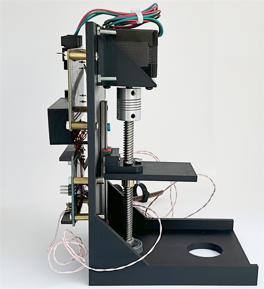
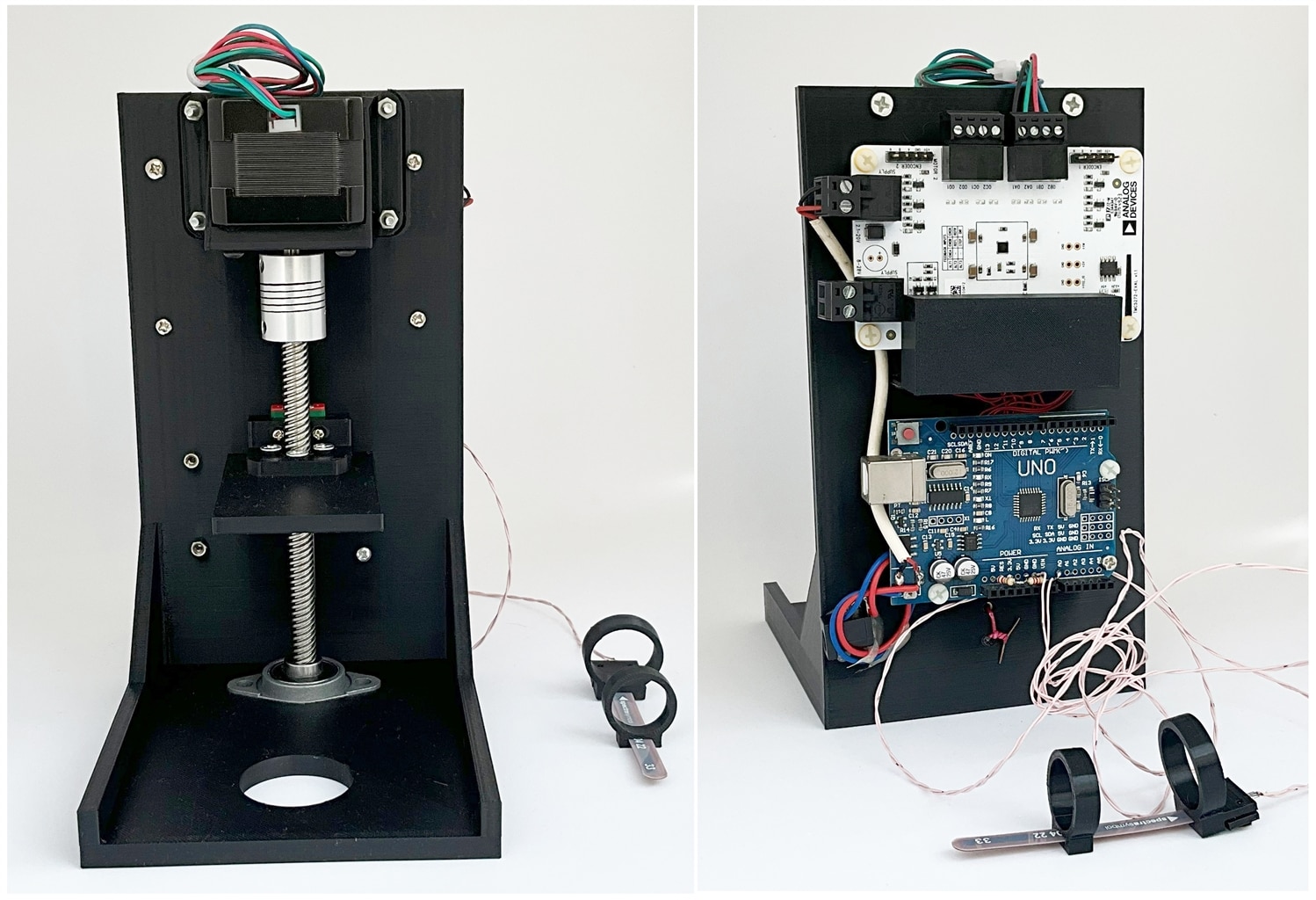
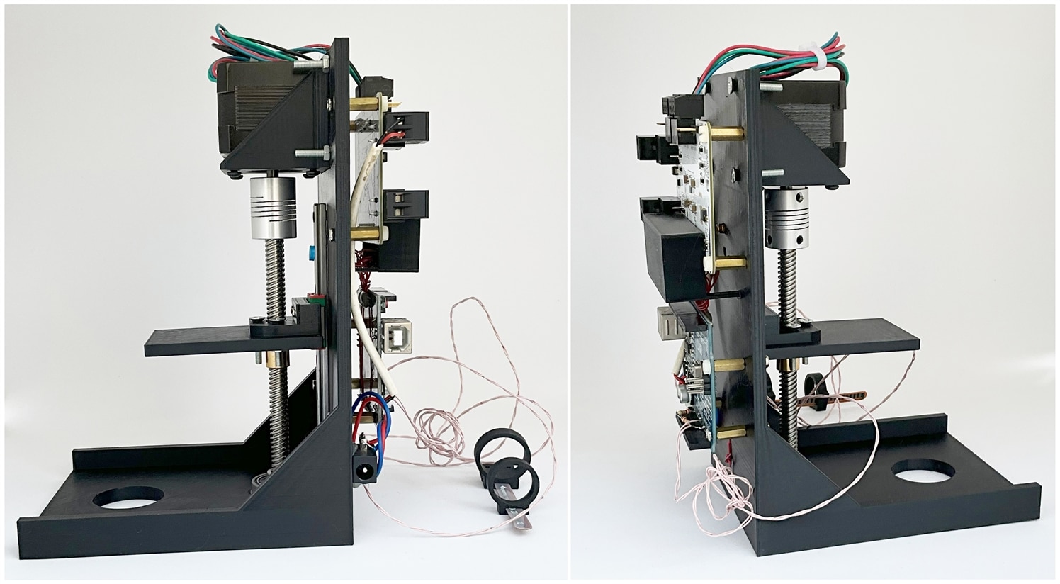
I made the final assembly using all the 3D printed parts, all the circuits and the mechanical components. I am surprise by seeing the final output of my creation. It is really cool, compact and stable. Most of the cases I used nuts and screws for assembly. Arduino barrel jack and the the power terminal of the TMC motor controller are connected together and attached with single barrel jack. The barrel jack is attached with the body of the main base.
My favorite image:
Front and Back side below:
Left side and Right side below:
Video Demonstration of my ASM Project
Watch the final video below:
My Previous Blogs Related to this Project
- Blog 1 - Part 1 (Unboxing & Testing the Trinamic Motor Controller)
- Blog 2 - Trinamic Motion Control using Arduino
- Blog 3 - Controlling Stepper Based on Flex Sensor
- Blog 4 - Adjusting Torque and Current Rating
- Blog 5 - 3D Printing and Assembly
- Blog 6 - Implementing StallGuard using Arduino
- Blog 7 - Working more with the Sensor
Attachments
All 3D Files.zipArduino code.zip
References
1. TMC5272-Evaluation Board (https://www.analog.com/en/resources/evaluation-hardware-and-software/evaluation-boards-kits/tmc5272-eval.html#eb-overview)
2. TMCL-IDE (https://www.analog.com/en/resources/evaluation-hardware-and-software/motor-motion-control-software/tmcl-ide.html)
3. QMot QSH4218 Stepper Motor (https://www.analog.com/en/products/qsh4218.html)
4. TMC5272 User Manual and Datasheet (https://www.analog.com/en/products/tmc5272.html)
5. TMC5272 Code Example (https://github.com/analogdevicesinc/TMCL-C-Examples)
6. For 3D Design - https://www.tinkercad.com/
7. Flex Sensor 2.2" - https://www.sparkfun.com/products/10264
9. 5mm to 8mm Flexible Shaft Coupling
11. 8mm Lead Screw and Brass Nut
12. Building a Better Stepper Motor System with StallGuard and CoolStep Technologies
13. Parameterization of StallGuard2 & CoolStep


Top Comments