


Blog 5: Adding Peripheral Sensors
We successfully connected the OV7670 camera to the SD card driver for storage of images. Now its time to make our camera smarter by adding sensors! The goal of this fifth blog is to interface sensors in our Security Camera.
Sensors make machines smarter. Machines become "smarter" when it has data to process and this data mostly comes from sensors. It "sense" the world and encode that data into binary which can be understood by any digital system. In fact, we had already used a sensor in my previous blog: the OV7670 camera. It converts the light information into pixel data of 16 bits. However, enough of the OV7670. Let us now talk of other kinds of sensors that we will add to our Security Camera.
PIR Sensor
I'm sure many of you had already used this sensor for your theft detection projects. If you had not yet play with this thing, this is your time. A passive infrared sensor (PIR sensor) is an electronic sensor that measures infrared (IR) light radiating from objects in its field of view. PIR sensors use a pair of pyroelectric sensors to detect heat energy in the surrounding environment. The PIR sensor I bought is the very common HC-SR501. It only has three pins and some trimmers for sensitivity:

When PIR sensor detects movement or heat energy, the digital OUT will go high.
Sound Sensor
As the name itself, it detects sound. The sound sensor has a thin piece of material called a diaphragm that vibrates when hit by sound waves which is akin to how our eardrum vibrates when hearing sound. This diaphragm alerts the system when a significant sound vibration is felt. The sound sensor I bought is similar to this:
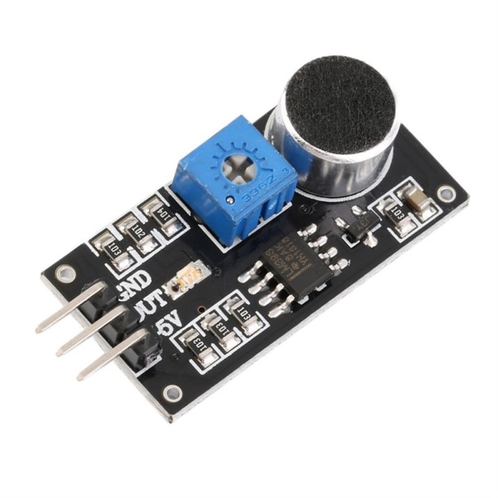
When the sensor detects sound past its set threshold(can be adjusted by the trimmers), the digital OUT will go low (active low).
Temperature Sensor
Now for the tricky part, we will also interface with a temperature sensor. The output of a temperature sensor is analog.I used the all very common LM35 temperature sensor:
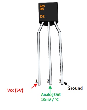
As you can see on the pin 2 description, Analog Out is 10mV/Celsius. It means that analog output voltage will increase by 10mV every time the temperature increase by 1 Celsius. For example. if the temperature is 30 Celsius, you will have an analog output voltage of 300mV (30Celsius*10mV/Celsius). Enough of how it works, the question is how can a digital device like the FPGA interface with an analog device like this temperature sensor? The answer is that we use Analog to Digital Converters (ADC).
XADC in CMOD S7
Fortunately, the Spartan 7 FPGA chip in the CMOD S7 has an analog to digital converter and is called XADC. The inputs for this XADC is multiplexed between the external and internal analog inputs. The internal analog input can be the internal temperature sensor of the chip. If you had tried programming the bitstream to the FPGA, you will likely see the XADC System Monitor which displays the current temperature of the chip. We can use this internal temperature sensor for this project but I decided not to since for the demonstration I will be using a real fire(from a lighter only) and I do not want to keep that near to the main chip of the FPGA. Thus, we will be using the external analog input.
The XADC interface is this:
module xadc_interface( //reads ADC output and store to register
    input wire clk, rst,
    input wire vaux5_p, vaux5_n, //pin 32
    input wire vaux12_p, vaux12_n,
    output reg[11:0] adc_0,adc_1,adc_2 //ADC CODE: adc_0(die temp) , adc_1(pin 32) , adc_2(pin33)
    );

    wire [4 : 0] channel_out;
    wire eoc_out;
    wire drdy_out;
    wire [15 : 0] do_out;
    //reg[11:0] adc_0,adc_1,adc_2; //ADC CODE: adc_0(die temp) , adc_1(pin 32) , adc_2(pin33)


    //register operation
    always @(posedge clk,posedge rst) begin
        if(rst) begin
            adc_0<=0;
            adc_1<=0;
            adc_2<=0;
        end
        else if(drdy_out)begin //read operation successful and data is now available at do_out
            if(channel_out==5'h00) adc_0<=do_out[15:4]; //die temp sensor (info at datasheet)
            if(channel_out==5'h15) adc_1<=do_out[15:4]; //pin 32  (info at datasheet)
            if(channel_out==5'h1c) adc_2<=do_out[15:4]; //pin 35  (info at datasheet)
        end
    end


    //XADC IP instantiation
    xadc_wiz_0 m0 (
      .di_in(),              // no write operation is needed
      .daddr_in({2'b00,channel_out}), // instantly read the channel(5bits) after conversion (daddr_in is 7bits)
      .den_in(eoc_out),            // start read operation at end-of-conversion
      .dwe_in(1'b0),            // always do read operation
      .drdy_out(drdy_out),        // ticks when do_out is available for reading
      .do_out(do_out),            // 12MSB is the ADC code (0-to-4095)
      .dclk_in(clk),          // input clk (12MHz for CMOD-S7)
      .reset_in(rst),        // input wire reset_in
      .vp_in(vp_in),              // NOT USED
      .vn_in(vn_in),              // NOT USED
      .vauxp5(vaux5_p),            // pin 32
      .vauxn5(vaux5_n),            // grounded for unipolar input
      .vauxp12(vaux12_p),          // pin 33
      .vauxn12(vaux12_n),          // grounded for unipolar input
      .channel_out(channel_out),  // channel converted by eoc_out
      .eoc_out(eoc_out),          // end-of-conversion
      .alarm_out(alarm_out),      // NOUT USED
      .eos_out(eos_out),          // NOT USED
      .busy_out(busy_out)        // NOT USED
);


endmodule
Note that this code is just an interface to the main IP used in XADC. So make sure you first instantiate the XADC IP. You can use the IP instantiation template added on my code to get an idea on what parameters you will use for instantiating the XADC IP. The possible inputs for this interface are the analog external input pins (pin 32 and 33) and the internal temperature sensor. I want to make the XADC interface as general as possible so that I can re-use this code in my future projects.
Connecting the Sensors to the Camera
Now that all three sensors are ready, how can we add it to the camera interface we did last time? The snippet of code to make the sensors work is this (this is already included in the camera driver code on blog 4),
rest: if(key_tick || pir_sensor || !sound_sensor || temp_sensor) begin
     lines_d=0;
     state_d=vsync_fedge;
 end
The logic is simple, the camera will start saving data to SD card if key_tick is pressed(de-bounced output of btn1) OR PIR sensor is high OR sound sensor is low(active-low) OR temperature sensor is active (reached the threshold). Very simple logic but will definitely make the Security Camera smarter.
Before we Proceed to the Final Blog
Did you remember on my third blog, when we tried storing ASCII letters to the SD card to test if the driver code is working. I did not implemented a file system that is why the computer was not able to view the real binary data we saved to it. We instead used the dd command to extract the data from sectors of the SD card.
That means when the camera sends pixel data to the SD card, we will not also be able to view the image normally when we open the directory of the SD card. That is pretty bad. Why store it to SD card if we cannot access it? The thing we can do is to use the dd command again to extract all sectors with the data of the image: sudo dd bs=512 count=1200 skip=2050 if=/dev/sdd of=sdcard.bin
Take note of the value of 1200 for count , this is not just some magic number. 1200 counts of 512 bytes is in fact the size of a whole frame:
1200 counts * 512 bytes/count = 614400 bytes
2 bytes/pixel * 640 pixels/line * 480 lines/frame= 614400 bytes/frame
And there you go, so if you want to retrieved 1 frame from your SD card use count=1200. Obviously, if you would want to retrieve 10 frames, the count should be 1200*10=12000. Let me remind again that skip=2050 is just the number of counts or 512 bytes skipped before retrieving the data. It is set to 2050 since that is what I set at the SD card driver (2050 seems to be always a safe sector). After extracting data from sectors of the SD card, the binary output must then be converted to an image. That might seem tedious so I made an MATLAB script for that,
function f = ov7670(MAX_IMAGES)
fid=fopen('sdcard.bin');
file=fread(fid);
k=1;
rgb_index=1;
while k<=(614400*MAX_IMAGES)
  pixel=file(k)*2^8 + file(k+1);
  k=k+2;
  r(rgb_index)=uint8((bitand(pixel,63488)/2^11)*2^3);
  g(rgb_index)=uint8((bitand(pixel,2016)/2^5)*2^2);
  b(rgb_index)=uint8((bitand(pixel,31))*2^3);
  rgb_index=rgb_index+1;
end

rgb_index=1;
foldername='OV7670_images';
mkdir(foldername);
for img_saved=1:MAX_IMAGES
  for width=1:480
      for length=1:640
         img(width,length,1)=r(rgb_index);
         img(width,length,2)=g(rgb_index);
         img(width,length,3)=b(rgb_index);
         rgb_index=rgb_index+1;
      endfor
  endfor
  imshow(img)
  num=num2str(img_saved);
  filename=strcat(foldername,'/','img',num,'.bmp')
  imwrite(img,filename);
endfor

end
This can run on Octave so you might opt for that since Octave is free and lighter compared to MATLAB. What this code do is simple, it reads the sdcard.bin that were extracted when we used the dd command. It will extract the red, green, and blue pixels by bit manipulation (magic numbers 63488, 2016, 31). This red, green, and blue pixels will be combined to make the original 640x480 image. To use this code just type ov7670(arg) on the command line. The arg is a number that pertains to how many frames you want to retrieve. Keep the number low(less than 10) since it will take a lot of time to process each of those images.
Preview for Next Blog
Now that everything is ready, we can now proceed to my final blog. Next stop: project demonstration and some final words.
6-Part Blog Series
- Security Camera #1: Project Proposal
- Security Camera #2: SD Card Interfacing
- Security Camera #3: Testing the SD Card Driver
- Security Camera #4: Interfacing with OV7670 Camera
- Security Camera #5: Adding Peripheral Sensors
- Security Camera #6: Project Demonstration and Final Words
To see more of my FPGA projects, visit my GitHub account: https://github.com/AngeloJacobo
References:
https://en.wikipedia.org/wiki/Passive_infrared_sensor
https://www.componentsinfo.com/hc-sr501-module-pinout-datasheet/
https://www.engineersgarage.com/lm35-description-and-working-principal/