


This is the first of two blogs that address the software for the mini fridge. In this blog, I will focus in particular on environment setup and peripheral configuration. In the next one, I will provide more details about the software implementation
Other posts in this serie
- ColdCase - Blog# 1 - Introduction
- ColdCase - Blog #2 - The refrigerated cell
- ColdCase - Blog #3 - Preparing the environment
- ColdCase - Blog #4 - The software
- ColdCase - Blog #5 - Final assembly
- ColdCase - Blog #6 - The Android app
- ColdCase - Blog #7 - Final assembly
1. Preparing the development environment
I chose to use MPLab X IDE as development environment. So I installed MPLab X IDE and the Harmony Configurator (which is a nice-and-easy tool to configure all the internal peripherals of the SAME51 microprocessor). The setup process was uneventful: I just followed the instructions on the Microchip website
The complete guides are
- https://www.microchip.com/en-us/education/developer-help/learn-tools-software/mcu-mpu/mplab-x-ide/install-guide
- https://ww1.microchip.com/downloads/en/DeviceDoc/How_to_Setup_MPLAB_%20Harmony_v3_Software_Development_Framework_DS90003232C.pdf
After this good start, problems arose. Apparently, MPLab X IDE has a plugin to configure MikroE Click boards. I spent many hours trying to make this plugin work, with no success. My guess is that the plugin is quite old and is no longer compatible with the newer versions of MPLab X.
If you want to give a try, here is the PDF with the setup instructions
https://ww1.microchip.com/downloads/en/DeviceDoc/release_notes_mikroEClickLibrary_v1_1_2.pdf
and here is a link to the plugin library (it was not easy to find, since the PDF does not provide clear information about the file position)
https://ww1.microchip.com/downloads/en/DeviceDoc/mikroEClickLibrary-1.0.27.zip
I found another library that looked promising
https://codeload.github.com/Microchip-MPLAB-Harmony/reference_apps/zip/refs/heads/master
but again the projects were not compatible with the latest versions of Harmony. After spending many hours trying to fix incompatibility issues unsuccessfully, I decided to give up and code the functions to access the Click boards from scratch.
2. Configuring the peripherals
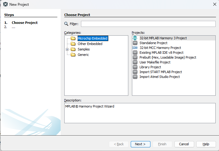
First of all, I created a new "Harmony 3" project in MPLab X IDE
Next, I configured all the peripherals I am going to use, namely
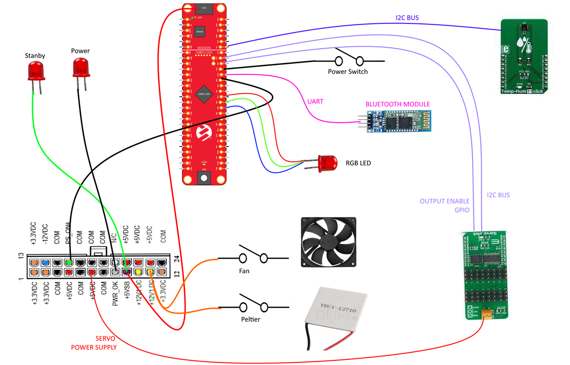
- I2C master controller to communicate with the Click boards. Actually, I used two I2C masters, because the two Click boards I selected have (by default) the same I2C slave address. On the Servo Click board, there are some soldered jumpers to change the I2C slave address, but, since I don't trust my soldering capabilities on SMD components, I am going to use a second I2C bus to overcome this problem
- A serial port for debug purposes. The USB debug chip mounted on the Curiosity Nano provides a virtual serial port that can be used to send debug messaged to a terminal
- 3 PWM signals to drive the RGB LED. PWMs can be generated by means of the TCC peripherals, which provides a certain number of PWM channels with the same period but different duty cycles. The initial idea was to use the Click Servo board, but the PWM frequency required to drive the servos is so slow that you clearly see LEDs flickering
- 1 GPIO configured as output to be used as "Output Enable" (OE) signal for the Servo Click board
- 2 GPIO configured as output to drive two further LEDs that will show the current status of the Peltier cell (on or off) and the status of the fan (on or off)
- 1 GPIO configured as output to drive the LED mounted on the Curiosity Nano board
- 1 GPIO configured as input to read the status of the push button mounted on the Curiosity Nano board (currently not used, but may be useful in a near future)
- 1 GPIO configured as input to read the status of the switch button mounted on case front panel
- 1 GPIO configured as output to drive the PS_ON# on the ATX power supply
A schema of the connections is shown in the following diagram
The components I had to "instantiate" in the Harmony Configurator are shown in this screenshot
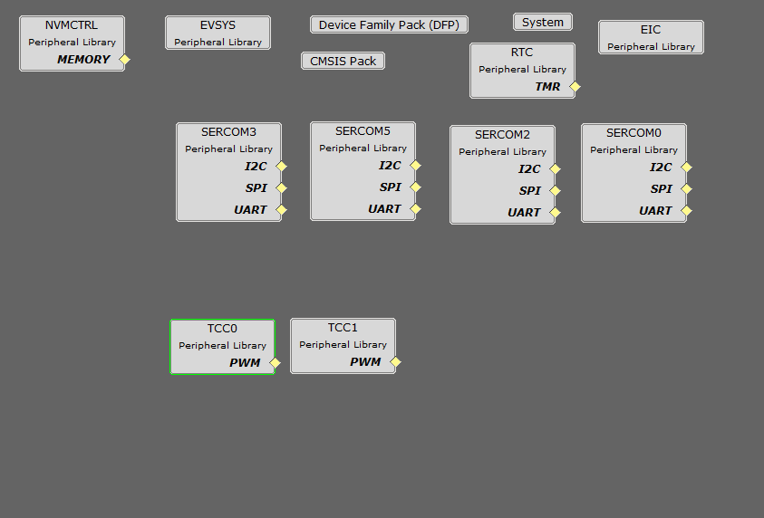
There are some components that are instantiated by default, namely
- NVMCTRL: is a default component that initializes the internal Flash memory
- EVSYS: another default component to log system events while debugging
- Device Family Pack: shows information about the package currently in use to generate code from the configuration
- CMSIS Pack: again, shows information about the package currently in use to generate code from the configuration
- System: provides an overview of the system configuration (for example ports, clocks, DMAs, etc). The configuration of each component can be changed here, but it's much simpler to change the configuration using the dedicated graphical interface for the specific peripheral
- EIC: enables specific external interrupts (for example, the push button on the Curiosity Nano board has been associated to interrupt handler here)
Here are the components I created
2.1 RTC
This block enables the RealTime Clock. I configured the RTC to generate an interrupt every millisecond
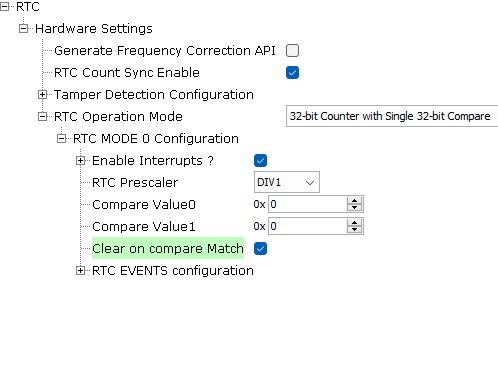
As you can see, the "RTC Prescaler" is set to DIV1. This means that the clock provided to the RTC peripheral is divided by one and, thus, an interrupt is generated at every clock cycle. You can easily check the frequency of the input clock by clicking "Tools" -> "Clock configuration"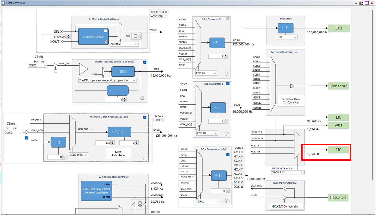
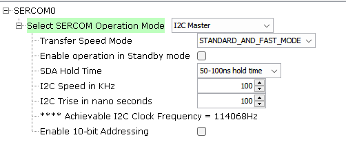
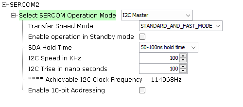
2.2 I2C master (SERCOM0 and SERCOM2)
As I said, I instantiated two I2C masters: the first one (named SERCOM0 in the datasheet) for the Servo Click board and the second one (named SERCOM2) for the Temp&Hum Click board
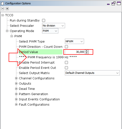
2.3 PWM signals (TCC0 and TCC1)
The TCC peripheral can generate (among the other things) PWM signal at a user-defined frequency. I need three PWMs to drive the RGB LED that provides a feedback about the temperature in the refrigerated cell. Despite each TCC can handle up to 7 PWM signals, I instantiated two peripherals (TCC0 and TCC1) due to some limitations in the pin multiplexing. In particular, I want to keep all the wirings on a single header. But there were only two pins that can be pinmuxed (or "connected") to TCC0 on the side of the board I selected. For this reason, I initialized another TCC peripheral (TCC1) to drive the third PWM signal
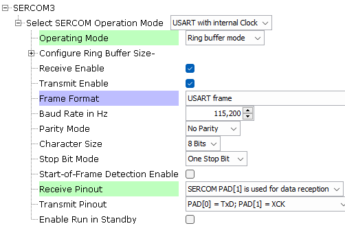
2.4 Bluetooth module UART (SERCOM3)
This port is used to communicate with the Bluetooth module. Since the module can send unsolicited messages, I chose "Ring buffer mode" as "Operating mode". This means that the driver implements a circular queue where received data is temporary stored until the application pulls out and process data
2.5 Debug UART (SERCOM5)
This is another UART that can be used in your application to send out debug messages and show them on a terminal application (for example, TeraTerm)
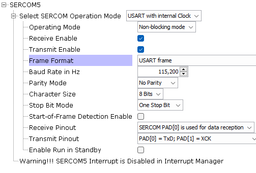
To write data to the serial port, a DMA channel is used, as shown in code snippet below, which transfer the content of the provided buffer to the serial port
static void print(uint8_t* txBuffer)
{
    isUSARTTxComplete = false;

    DMAC_ChannelTransfer(DMAC_CHANNEL_0, txBuffer, \
        (const void *)&(SERCOM5_REGS->USART_INT.SERCOM_DATA), \
        strlen((const char*)txBuffer));
}
3. Pinout
Given this configuration, the resulting pinout is shown in the following diagram
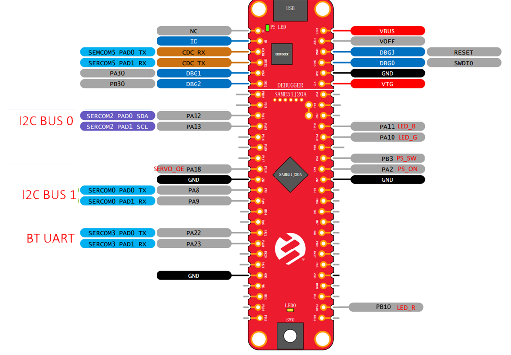
Most of the signals are already wired on Curiosity kit. The only signals I have to wire are
- the Bluetooth module UART
- the RGB LED PWMs (LED_R, LED_G and LED_B)
- the PS_SW input (this is the input from the power switch button on the case's front panel)
- the PS_ON output (this signal will be connected to the PS_ON# pin of the ATX connector)

