In this post, I will show how I built the refrigerated cell of the mini fridge
Other posts in this serie
- ColdCase - Blog# 1 - Introduction
- ColdCase - Blog #2 - The refrigerated cell
- ColdCase - Blog #3 - Preparing the environment
- ColdCase - Blog #4 - The software
- ColdCase - Blog #5 - Final assembly
- ColdCase - Blog #6 - The Android app
- ColdCase - Blog #7 - Final assembly
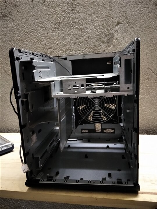
First of all, I removed the bottom part of the frame that used to host the Hard Disk drives. This will let me create a larger refrigerated cell
| {gallery}Metalwork |
|---|
|
|
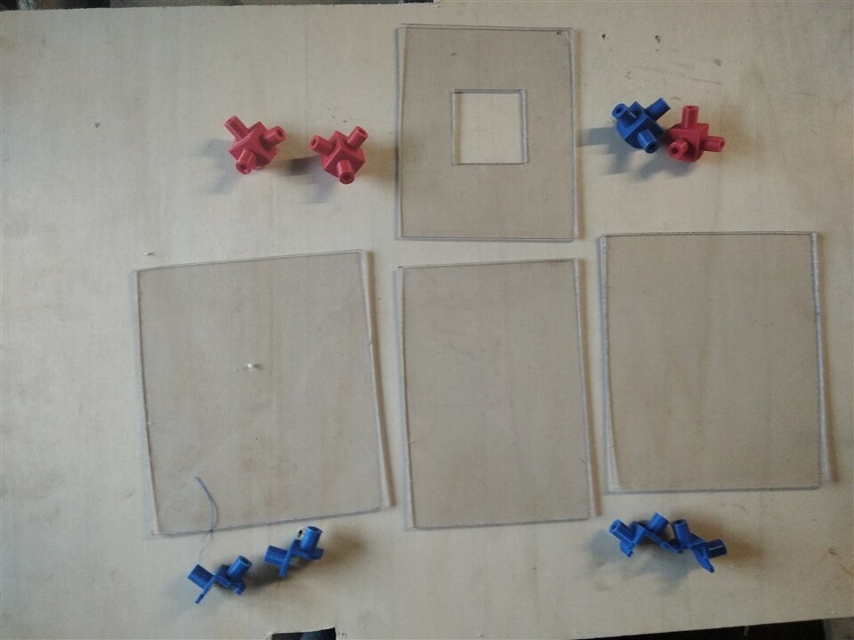
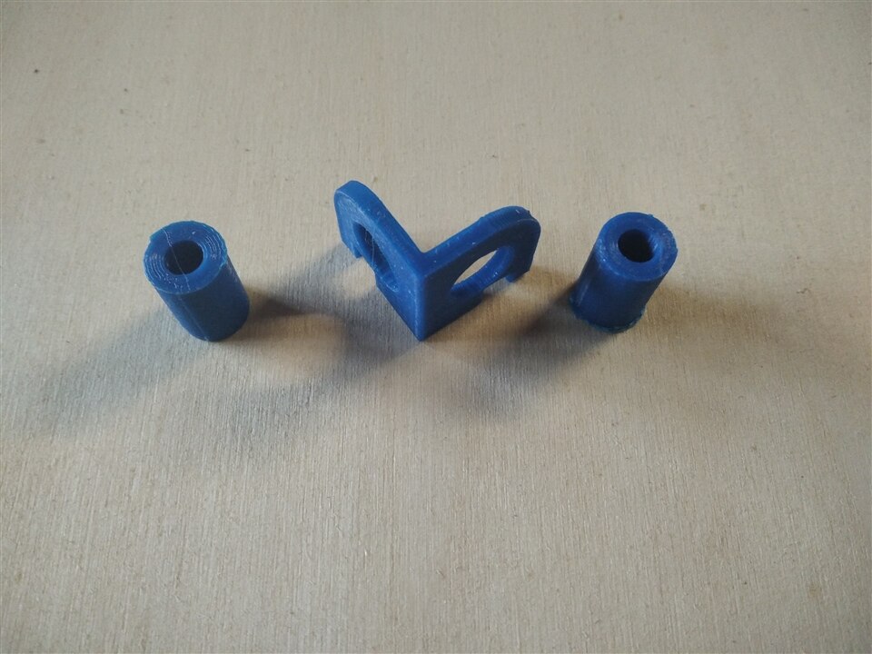
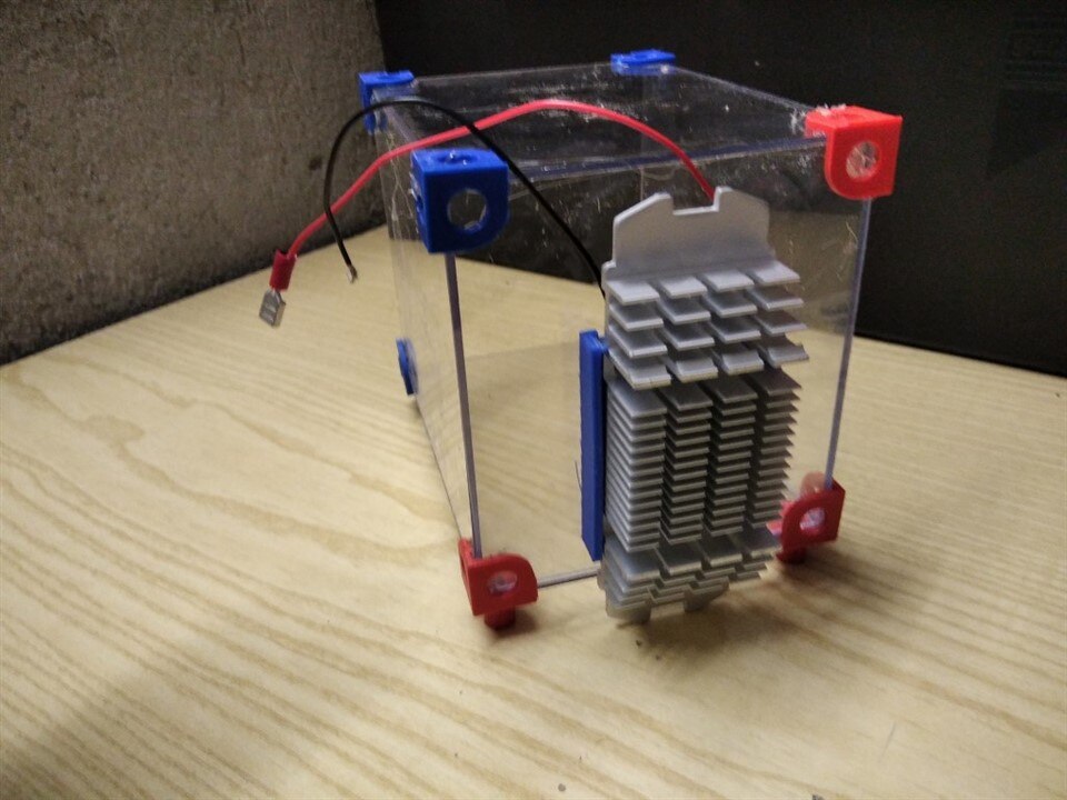
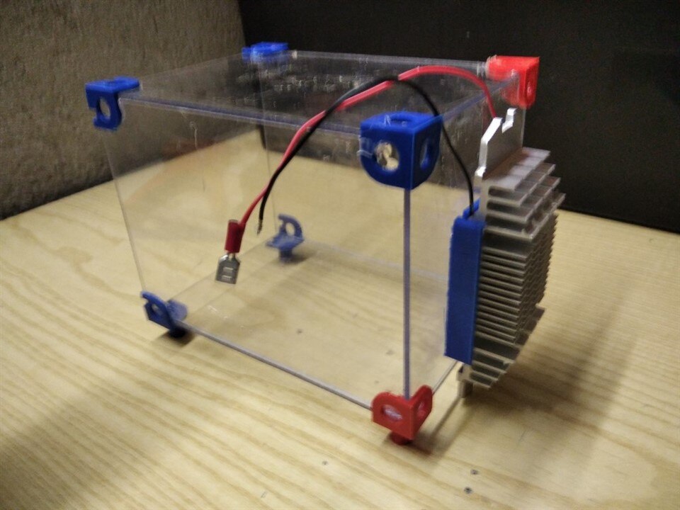
Then, I created a box made of Plexyglass and angular brackets. These will be the internal walls of the fridge. Brackets have 15-millimeters supports to keep the right distance from the external walls.
| {gallery}The refrigerated cell |
|---|
|
|
|
|
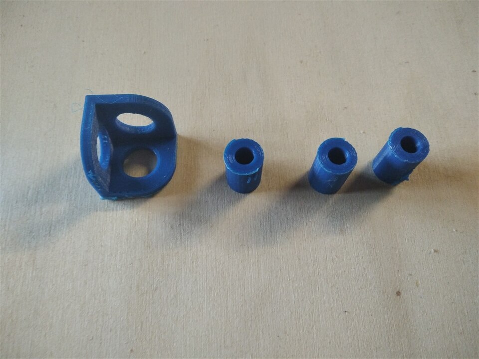 |
Brackets that are placed on the front side of the box also have some insets to keep a frame in place.
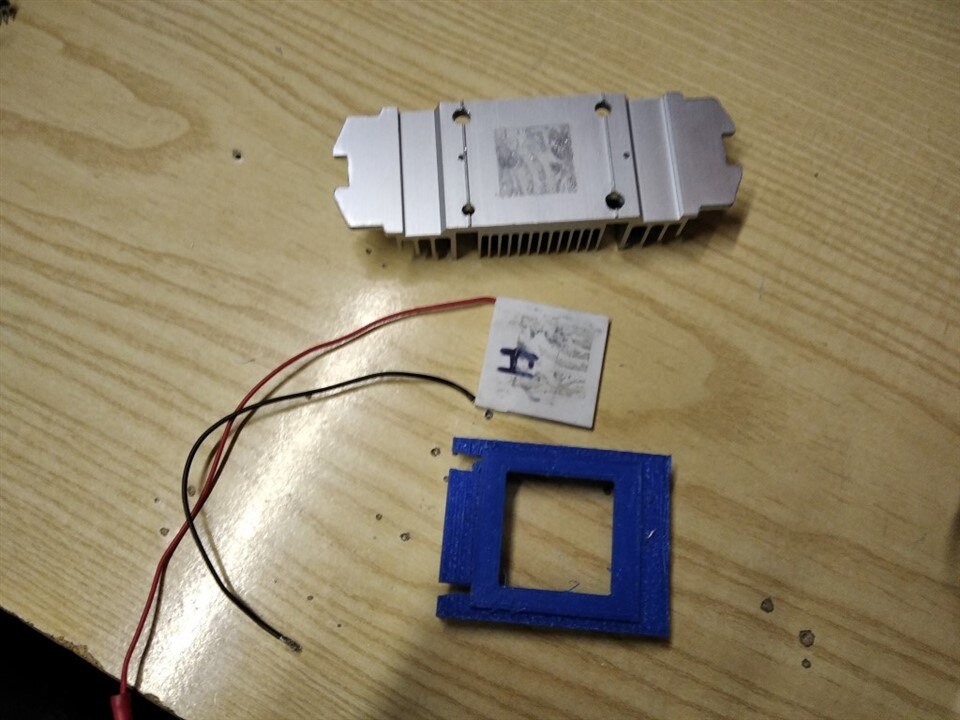
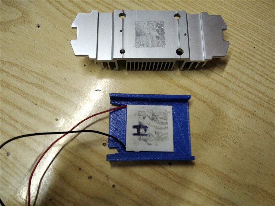
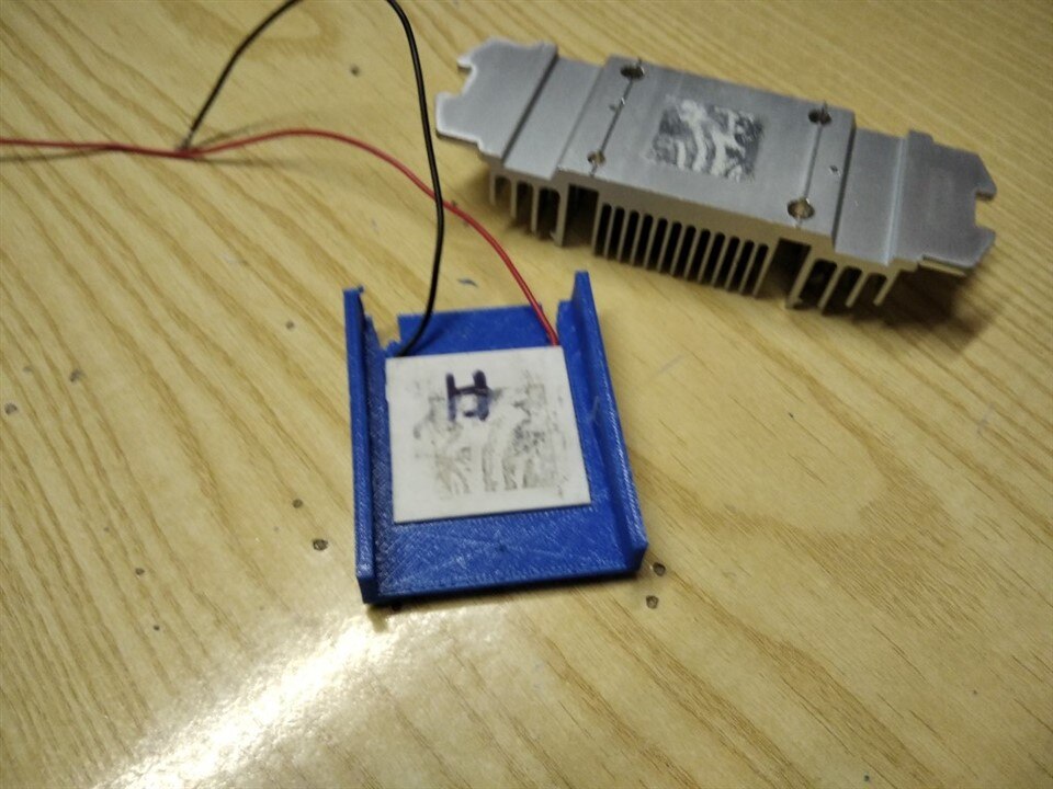
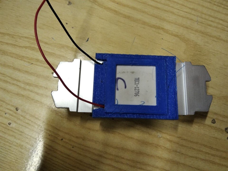
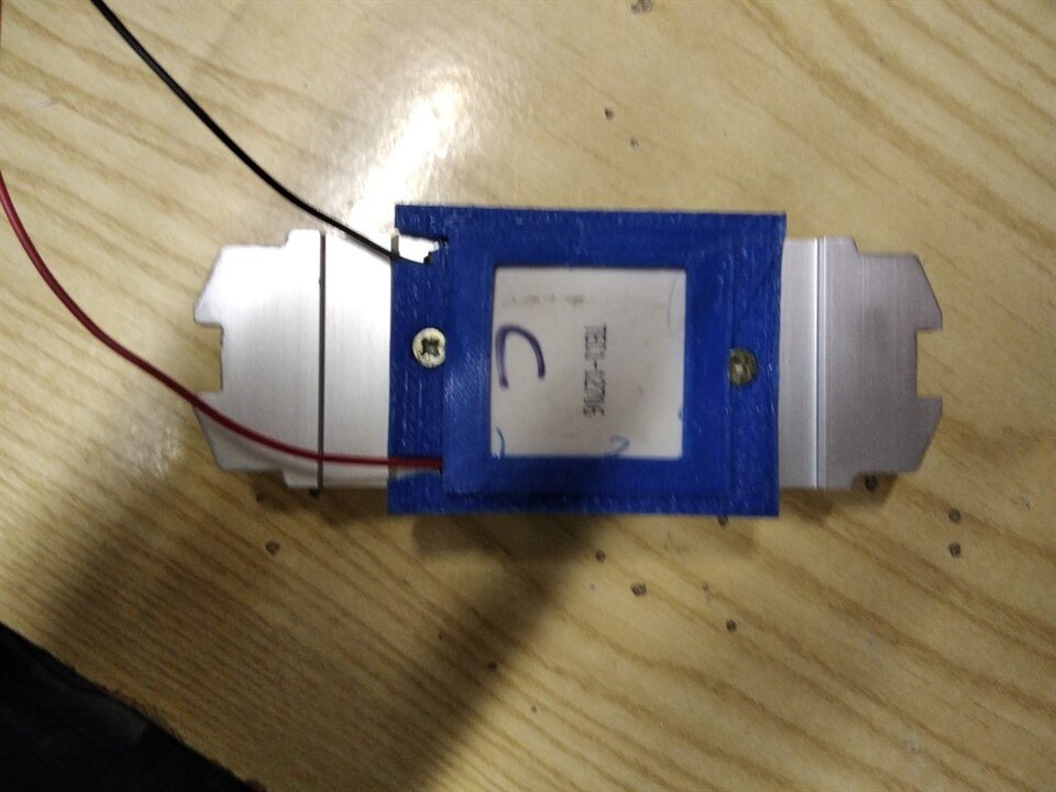
The wall on the back has a hole for the Peltier cell. Peltier cell and heatsink are kept in place by a 3D-printed support made of TPU. I chose TPU because it has a better heat resistance and is flexible. Thanks to this flexibility, I can position both the Peltier cell and the heatsink without need for extra screws.
| {gallery}Installing the Peltier Cell |
|---|
|
|
|
|
|
|
|
|
|
|
 |
|
|
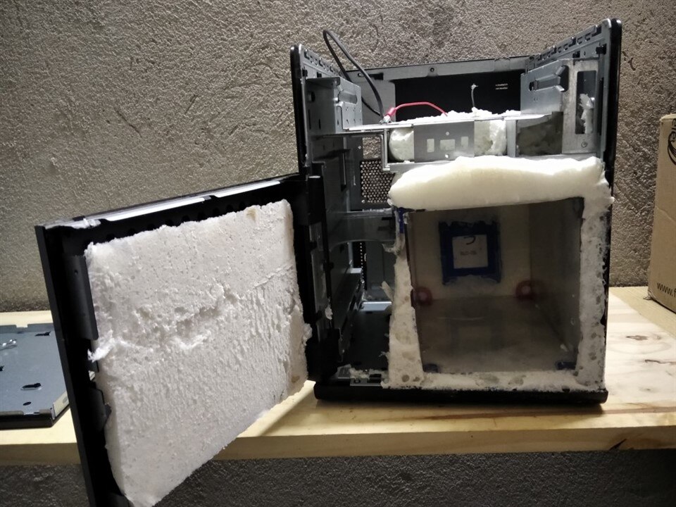
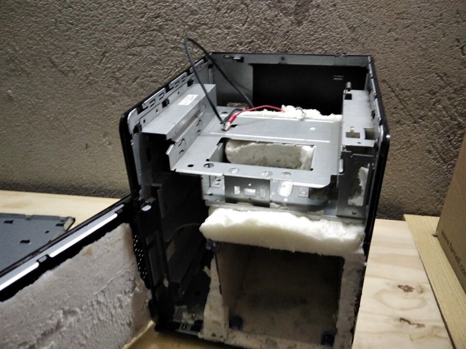
Box has been put in place and covered with expanded polyurethane foam. Excesses have then been trimmed using a cutter
| {gallery}Cell covered with foam |
|---|
|
|
|
|
|
|
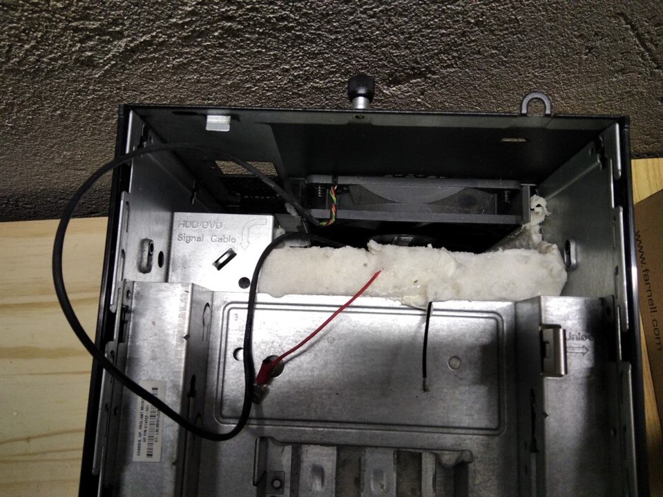
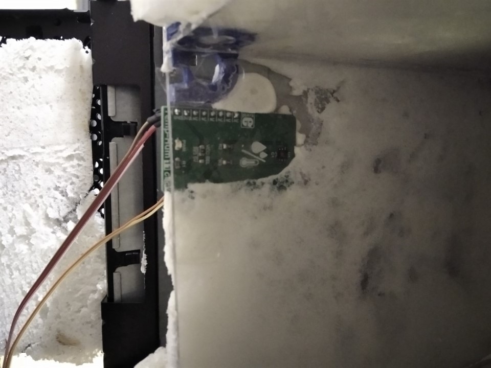
The Temp&Hum Click board has been put in place and covered with insulating material (not foam, to make it easy to access and replace in case of issues)
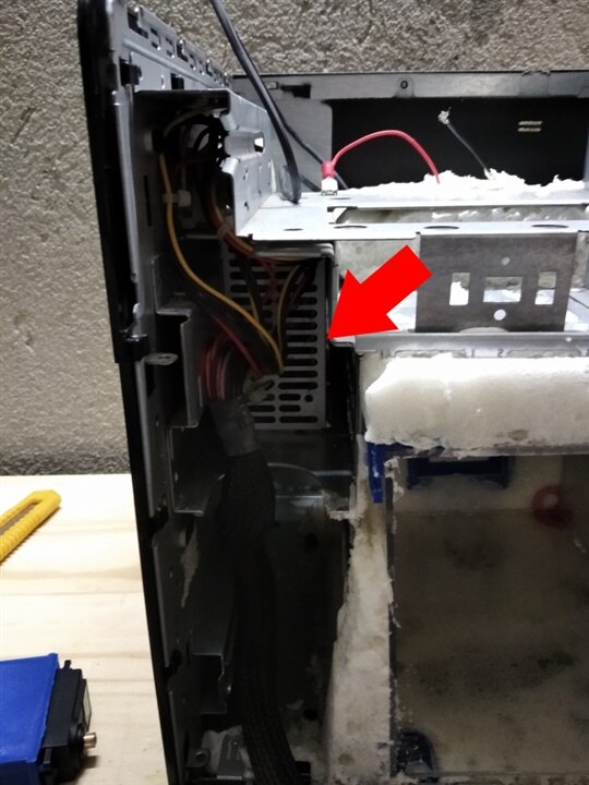
Finally, I mounted back in place the power supply
Everything is ready to install the control board with all the electronic components. Stay tuned for the next blog!

