In this post, I will talk about the software implementation. To drive the Click boards, I customized the functions provided by the MikroSDK
Other posts in this serie
- ColdCase - Blog# 1 - Introduction
- ColdCase - Blog #2 - The refrigerated cell
- ColdCase - Blog #3 - Preparing the environment
- ColdCase - Blog #4 - The software
- ColdCase - Blog #5 - Final assembly
- ColdCase - Blog #6 - The Android app
- ColdCase - Blog #7 - Final assembly
1. Driving the servos
Servo Click is a compact add-on board that contains a PWM servo driver with voltage sensing circuitry. This board features the PCA9685, an integrated 12-bit, 16-channel PWM driver, which can be configured to either sink 25mA per channel or drive each channel sourcing up to 10mA. It can be used to simultaneously control 16 servo motors, each with its own programmable PWM signal. The frequency of the control PWM signal can be programmed in the range from 24 Hz to 1526 Hz, which is an ideal range for driving various types of servos.
The output signal frequency is determined by the Prescaler value, which is written to the appropriate PCA9685 register. The output channels can be set either in the open-drain or in the push-pull configuration. In the first case, they will be able to sink up to 25mA from up to 5V power supply, while in the second case, they will be able to both drive with up to 10mA or sink up to 25mA.
The Servo Click also has an accurate 16bit A/D converter: the LTC2497 from Analog Devices used to sample the voltage drop across the shunt resistor on each of the 16 channels giving feedback on the servo current consumption. The ADC uses an accurate reference of 2.048V provided by an onboard reference voltage regulator MAX6106 from Maxim Integrated. An extremely low noise of this ADC coupled with a low reference voltage allows small voltage drops across the shunt resistor to be accurately converted. This feature is perfect to check if the front door is locked or stuck and can not be opened by the servo.
Servo Click communicates with MCU using the standard I2C 2-Wire interface with a frequency up to 100kHz in the Standard, up to 400 kHz in the Fast, and up to 1MHz in the Fast-Plus mode. It also has an external connector that can provide more power for servos that operate with heavier loads. That's why the SMD jumper labeled as VCC MOT should be at the EXT position. In this case, an external PSU that can provide more current can be used.
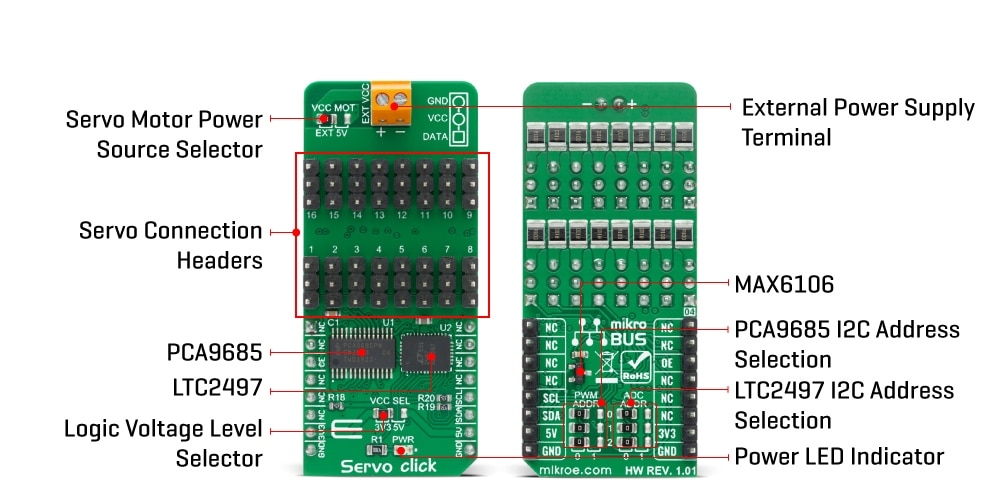
To drive the Servo Click board, I got inspiration from the library provided by the MikroSDK (available here https://codeload.github.com/MikroElektronika/mikrosdk_click_v2). The new functions reflect the overall structure of the original library. I simply removed all the dependencies from the MikroSDK and replaced the calls related to I2C bus with the corresponding functions provided by the Harmony 3 framework.
For example, this is the original code (from the microsdk_click library) to read a register
void servo_generic_read_of_pca9685 ( servo_t *ctx, uint8_t reg, uint8_t *data_buf, uint8_t len )
{
i2c_master_set_slave_address( &ctx->i2c, ctx->slave_address_of_pca9685 );
i2c_master_write_then_read( &ctx->i2c, ®, 1, data_buf, len );
}
void servo_generic_read_of_ltc2497 ( servo_t *ctx, uint8_t reg, uint8_t *data_buf, uint8_t len )
{
i2c_master_set_slave_address( &ctx->i2c, ctx->slave_address_of_ltc2497 );
i2c_master_write_then_read( &ctx->i2c, ®, 1, data_buf, len );
}
and this is how I changed
void servo_generic_read_of_pca9685 ( uint8_t reg, uint8_t *data_buf, uint8_t len )
{
SERCOM2_I2C_WriteRead(servo_ctx.slave_address_of_pca9685, ®, 1, data_buf, len);
while (SERCOM2_I2C_IsBusy())
;
}
void servo_generic_read_of_ltc2497 ( uint8_t reg, uint8_t *data_buf, uint8_t len )
{
SERCOM2_I2C_WriteRead(servo_ctx.slave_address_of_ltc2497, ®, 1, data_buf, len);
while (SERCOM2_I2C_IsBusy())
;
}
As I said, I am going to use three servos
- one servo to switch on the PC fan
- one servo to switch on the Peltier cell
- one servo to open the front door
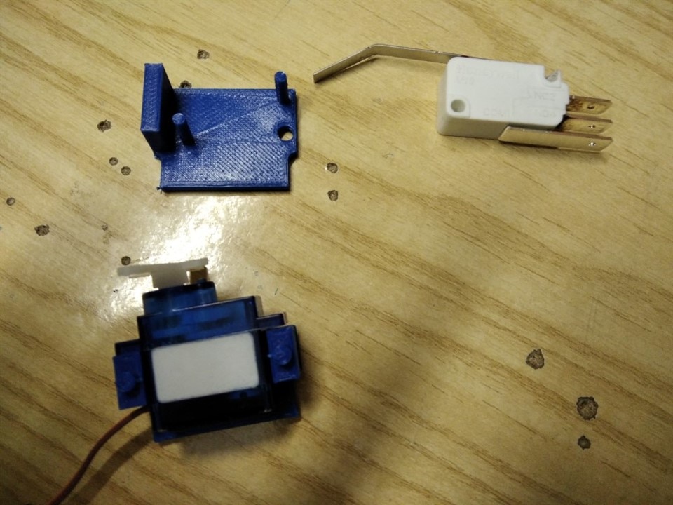
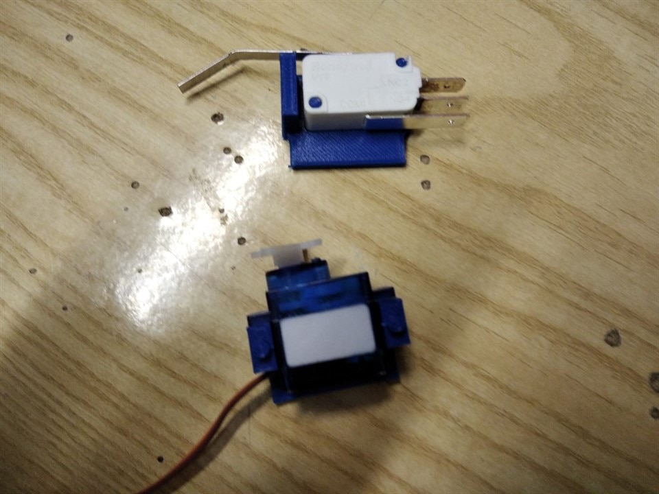
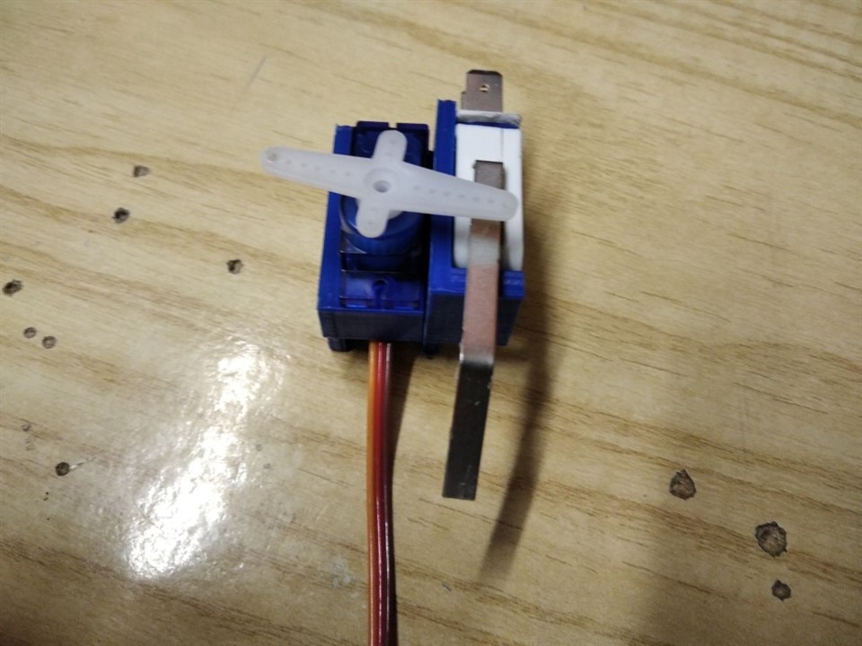
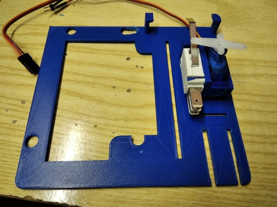
Here is how the servos are mounted to press the switches
| {gallery}Servo and switch |
|---|
|
|
|
|
|
|
|
|
|
|
2. Reading the temperature
Temp-Hum Click is a temperature and humidity sensing Click board, equipped with the HDC1080, a high accuracy digital humidity, and temperature sensor. Its key features are its low power consumption, and the measurement accuracy achieved with that much energy. The HDC1080 sensor can sense the relative humidity (RH) with the accuracy of ±2%, while the temperature can be sensed with the accuracy up to ±0.2⁰C. It has a 14-bit measurement resolution, and it can be operated over a wide supply voltage range, allowing it to be interfaced with both 5V and 3.3V MCUs with no additional components required.
Internally, two sensors are connected to the 14-bit ADC section, which can be set to sample measurements with the resolution of 8, 11 or 14 bits, based on the measurement (integration) time. The OTP memory holds the calibration coefficients that are applied to the measured value and the results are stored on the output registers, in the MSB/LSB format. These values are then used in formulas found in the HDC1080 datasheet so that the final temperature or relative humidity data can be calculated.
HDC1080 IC is a very low power consuming device and it can work in two modes: sleep and active (measurement) mode. The device enters the sleep the mode as soon as possible, in order to save power. This makes the HDC1080 suitable to be used for battery-powered applications. In these applications, the HDC1080 can spend most of the time in the sleep mode that has a typical current consumption in the magnitude of nanoamperes. The measurement is triggered after the command is sent over the I2C interface. As soon as the single measurement is finished, the device falls back to a sleep mode. The host should wait for the acquisition to be completed before reading the output registers.
The heating element can be used to reduce the offset which is a common problem for most RH sensors. It also helps with the condensation, evaporating the excess moisture. The current consumption is increased when the heater is on. It can be enabled by configuring the appropriate register, but it won't be actually activated until a measurement is triggered. Therefore, to increase its temperature, measurement frequency should be increased.
Here I use a different I2C port to read temperature and humidity. After all, I add to place the sensor close to the Peltier cell and some soldering and wiring was required in any case. Changes to the original code from the MicroSDK Click library are related to the low-level API to access the I2C peripheral. This is the original code
uint16_t temphum11_read_data ( temphum11_t *ctx, uint8_t reg )
{
    uint8_t write_reg[ 1 ];
    uint8_t read_reg[ 2 ] = { 0 };
    uint16_t read_data = 0;

    write_reg[ 0 ] = reg;

	i2c_master_write( &ctx->i2c, write_reg, 1 );
	com_delay();
	i2c_master_read( &ctx->i2c, read_reg, 2 );

    read_data = read_reg[ 0 ];
    read_data = read_data << 8 ;
    read_data = read_data | read_reg[ 1 ];

    return read_data;
}
And this is the modified code that uses the MPLab APIs
uint16_t temphum11_read_data ( uint8_t reg )
{
    uint8_t write_reg[ 1 ];
    uint8_t read_reg[ 2 ] = { 0xff, 0xee };
    uint16_t read_data = 0;

    write_reg[ 0 ] = reg;

    SERCOM0_I2C_Write(TEMPHUM11_DEVICE_SLAVE_ADDR, write_reg, 1);
    while (SERCOM0_I2C_IsBusy())
        ;

    SYSTICK_DelayMs(10);

    SERCOM0_I2C_Read(TEMPHUM11_DEVICE_SLAVE_ADDR, read_reg, 2);
    while (SERCOM0_I2C_IsBusy())
        ;

    read_data = read_reg[ 0 ];
    read_data = read_data << 8 ;
    read_data = read_data | read_reg[ 1 ];

    return read_data;
}
3. Driving RGB LEDs
To drive RGB LEDs, I instantiated two instances of the TCC peripheral in Harmony 3. TCCs are configured to work in PWM mode. This means that the output channels (WO[x], where x ranges from 0 to 7) are driven according to the below diagram
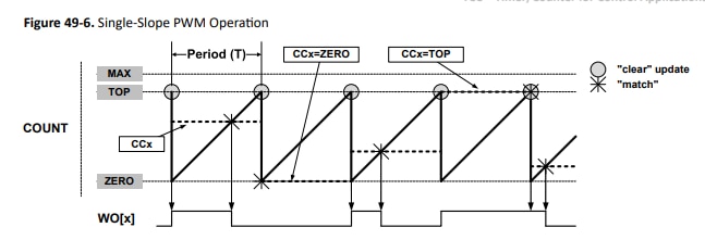
WO[x] is set to "high" when the value of the counter register is reset to 0. the counter register is incremented at every clock cycle and, when the value reaches the values user has written in the CCx register, the WO[x] is reset. In other words, the CCx register determined the PWM duty cycle. This register can be written with any value from 0 to TOP
The TOP value (which determines the PWM period) has been set to 30000. The PWM frequency is about 2 kHz, which is high enough to provide a flicker-free regulation of the luminosity. The CCx register must be set to 0 to switch off the LED, or to 30000 to have full luminosity.
Here is the code to set a specific color on the RGB LED. What I am doing here is to get the Red, Green and Blue components of the color to show, map the values in the range (0.255) to the range (0..30000) and finally set the TCC's CCx register
#define RGBLED_MIN      0
#define RGBLED_MAX      30000

static uint32_t rgbled_map(uint8_t v)
{
    return ((uint32_t)v * RGBLED_MAX) / 255;
}

void rgbled_update(uint8_t r, uint8_t g, uint8_t b)
{
    TCC0_PWM24bitDutySet(TCC0_CHANNEL0, rgbled_map(r));
    TCC0_PWM24bitDutySet(TCC0_CHANNEL2, rgbled_map(g));
    TCC0_PWM24bitDutySet(TCC0_CHANNEL3, rgbled_map(b));
}
The RGB LED I recycled from the case has common anode, so the connection diagram is as shown below
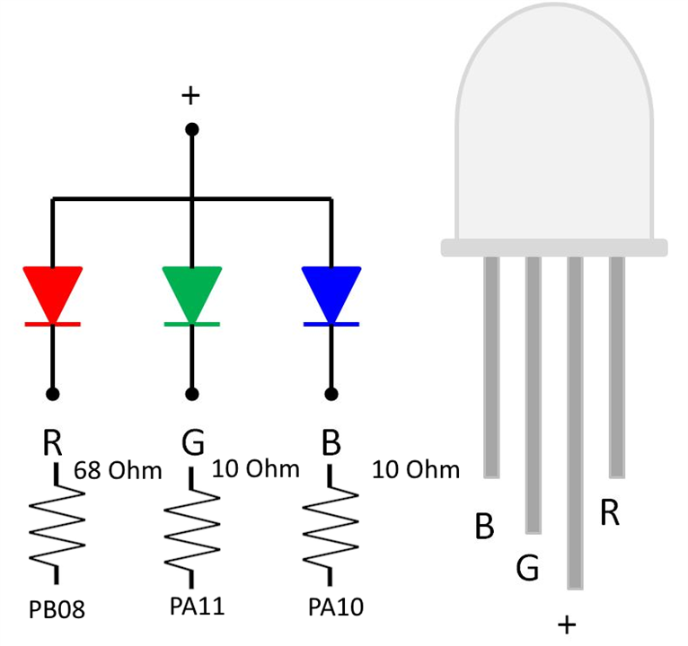
The "+" pin is connected to 3.3V, so, keeping in mind the forward voltage of LEDs (about 2V for red LED and about 3V for green and blue LEDs) and assuming a current of 20 mA, the resistors to add in series are 68 ohm for the red LED and 10 ohm for green and blue LEDs.
The RGB LED will provide a visual feedback of the refrigerated cell temperature. The color will range from blue (when temperature is close to the lowest possible value) to red (when temperature approaches the highest possible temperature). To calculate the color that corresponds to a given temperature, I implemented the following algorithm. I calculate a normalized temperature, which takes a value from 0 to 1, then, based on the normalized temperature, I calculate the amount of red and blue.
RGBLed::RGBColor RGBLed::temperatureToRGB(int temperature) {
    // Define the temperature range (adjust as needed)
    float min_temp = -5.0;
    float max_temp = 40.0;

    if (temperature < min_temp)
        temperature = min_temp;
    if (temperature > max_temp)
        temperature = max_temp;

    // Map temperature to a value between 0 and 1
    float normalized_temp = (float)(temperature - min_temp) / (max_temp - min_temp);

    // Interpolate between blue (cold) and red (hot) using the normalized temperature
    int blue = (int)((1.0 - normalized_temp) * 255.0);
    int red = (int)(normalized_temp * 255.0);
    int green = 0;  // You can modify this based on your preference

    // Ensure values are within the valid RGB range (0 to 255)
    red = (red < 0) ? 0 : ((red > 255) ? 255 : red);
    blue = (blue < 0) ? 0 : ((blue > 255) ? 255 : blue);
    green = (green < 0) ? 0 : ((green > 255) ? 255 : green);

    RGBColor rgb_color = {red, green, blue};
    return rgb_color;
}


