element14 Community
element14 Community
    Register Log In
  • Site
  • Search
  • Log In Register
  • Community Hub
    Community Hub
    • What's New on element14
    • Feedback and Support
    • Benefits of Membership
    • Personal Blogs
    • Members Area
    • Achievement Levels
  • Learn
    Learn
    • Ask an Expert
    • eBooks
    • element14 presents
    • Learning Center
    • Tech Spotlight
    • STEM Academy
    • Webinars, Training and Events
    • Learning Groups
  • Technologies
    Technologies
    • 3D Printing
    • FPGA
    • Industrial Automation
    • Internet of Things
    • Power & Energy
    • Sensors
    • Technology Groups
  • Challenges & Projects
    Challenges & Projects
    • Design Challenges
    • element14 presents Projects
    • Project14
    • Arduino Projects
    • Raspberry Pi Projects
    • Project Groups
  • Products
    Products
    • Arduino
    • Avnet & Tria Boards Community
    • Dev Tools
    • Manufacturers
    • Multicomp Pro
    • Product Groups
    • Raspberry Pi
    • RoadTests & Reviews
  • About Us
    About the element14 Community
  • Store
    Store
    • Visit Your Store
    • Choose another store...
      • Europe
      •  Austria (German)
      •  Belgium (Dutch, French)
      •  Bulgaria (Bulgarian)
      •  Czech Republic (Czech)
      •  Denmark (Danish)
      •  Estonia (Estonian)
      •  Finland (Finnish)
      •  France (French)
      •  Germany (German)
      •  Hungary (Hungarian)
      •  Ireland
      •  Israel
      •  Italy (Italian)
      •  Latvia (Latvian)
      •  
      •  Lithuania (Lithuanian)
      •  Netherlands (Dutch)
      •  Norway (Norwegian)
      •  Poland (Polish)
      •  Portugal (Portuguese)
      •  Romania (Romanian)
      •  Russia (Russian)
      •  Slovakia (Slovak)
      •  Slovenia (Slovenian)
      •  Spain (Spanish)
      •  Sweden (Swedish)
      •  Switzerland(German, French)
      •  Turkey (Turkish)
      •  United Kingdom
      • Asia Pacific
      •  Australia
      •  China
      •  Hong Kong
      •  India
      •  Japan
      •  Korea (Korean)
      •  Malaysia
      •  New Zealand
      •  Philippines
      •  Singapore
      •  Taiwan
      •  Thailand (Thai)
      •  Vietnam
      • Americas
      •  Brazil (Portuguese)
      •  Canada
      •  Mexico (Spanish)
      •  United States
      Can't find the country/region you're looking for? Visit our export site or find a local distributor.
  • Translate
  • Profile
  • Settings
element14's The Ben Heck Show
  • Challenges & Projects
  • element14 presents
  • element14's The Ben Heck Show
  • More
  • Cancel
element14's The Ben Heck Show
Documents Winners Announcement: Ben Heck's Raspberry Pi Bitscope Mod!
  • Blog
  • Forum
  • Documents
  • Polls
  • Files
  • Members
  • Mentions
  • Sub-Groups
  • Tags
  • More
  • Cancel
  • New
Join element14's The Ben Heck Show to participate - click to join for free!
Actions
  • Share
  • More
  • Cancel
Engagement
  • Author Author: tariq.ahmad
  • Date Created: 24 Aug 2017 4:29 PM Date Created
  • Last Updated Last Updated: 10 Oct 2017 1:41 PM
  • Views 6177 views
  • Likes 13 likes
  • Comments 46 comments
Related
Recommended

Winners Announcement: Ben Heck's Raspberry Pi Bitscope Mod!

image

element14's The Ben Heck Show

Join the Ben Heck team every week for amazing hacks! Watch them build and mod community-inspired projects using electronics!

Back to The Ben Heck Show homepage image

Connect with TBHS
Featured Bonus Materials
See All Episodes


{tabbedtable} Tab LabelTab Content
Winners Announcement

Congratulations to  guillaume9433 you are the winner of Ben Heck's Raspberry Pi Bitscope Mod!


His DIY Test Equipment idea was a 0-24V 8A -5V +5V 2A Power Supply Made with Affordable Adjust DC-DC Converters.


He's replacing an oscilloscope he can no longer use with Ben Heck's Raspberry Pi Bitscope Mod!

Winning Entry

guillaume9433 writes:


Hello , the first test equipment is the power suply . yes without energy, nothings to test.

So my DIY test equipment is a power suply 0-24v 8A -5v +5v 2A made with afordable  adjust dc-dc converters.


image

image

later i will post in DIY Test Equipment section schematic, charge tests and improvements.


An other thing, for test this i use a monstous fat and old scope (find at  the botton of shed):

image

It isn't possible to use this again, my wife don't love this living room embleshiment, so bitescope would be a great substitude

Highlights

gramboymicro  writes:


I know this is several paragraphs long AND a picture, but it is a very in-depth analysis of my idea.


So, there are a lot of ideas for test equipment that I have. A Linux-based tablet similar to that of Microsoft's Surface Pro series? No, too casual. A Raspberry Pi-based clone of the GPD Win? Sounds cool. With almost the exact same functions? Oh no. Too unoriginal. Maybe we could redesign the clam shell idea for an RPi3 Portable and make it something great.


So we could keep the clam shell design and handheld form factor. But how original can we make it? Well, let's look at the inspiration, the GPD Win. IT has a clam shell design, a game-pad and keyboard and several built-in input methods. Multiple Input Methods. That's what this idea is based around. So lets think. Right now, it sounds like a fancy DS with an RPi3 inside. Another inspiration that came up (came up RIGHT HERE when writing this) could be the Nintendo Switch, and the versatility of it, and how there is the potential for so many accessories. But then we have to still think about multiple input methods.


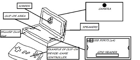
The Switch's JoyCons come on and off, being able to be removed. And when removed, they can still be used as input devices, wireless or not. There's an idea. Attachable input methods that can be used wireless or through a direct connection. An Idea could be there is the camera, screen and speakers in the top-half, and in the bottom there is an open space for accessories. In the open space- at the bottom, there would be the 4 USB ports from the RPi3. Those could be used for accessories. Also in this open space, closer to the top, there would be standoffs where the wireless accessories could clip on. These accessories could include a trackpad, keyboard, game controller, and more. And Heck, why not place he GPIO header in the open space, by the USB ports. That way specially designed accessories could attach to the GPIO header, and those could be more Test-Oriented. Like LEDs, and other things. And the USB ports could be there to use Wireless accessories too. And while we're at it, make a space at the top of this space, a cut-out so you could have your accessory, say, a game controller, and a USB-wired connection, say, a keyboard, and have the wire run out from under.


Summary? Have a 3DS-esque Linux-based RPi3 Portable, with an area on the bottom to clip on accessories like track pads, keyboards, game controllers, and the GPIO Header available for LED indicators or other GPIO-based addons. Also, you can use the clip-on accessory, and still use another wireless input device in the hidden USB ports underneath the clip-on accessory.


But how could it be used? Server Maintenance, Testing Linux applications, RPi Project Parts, like LED Indicators, Power Buttons, and maybe even some of the things on the Bitscope, and much, much more. It is just an RPi3 in a fancy case, so the application is only limited by how you use it.


image


gpolder writes:


As a radio ham I would rather like to have kind of a spectrum analyser. Unfortunately these are real expensive. Now with the advent of software defined radio there are cheaper ways to monitor the output  spectrum of our home brew equipment.

I found a very nice idea at adafruit (https://learn.adafruit.com/freq-show-raspberry-pi-rtl-sdr-scanner/overview ) where a SDR-RTL TV dongle is used to display the spectrum between 25 and 1800 MHz.

I replicated that design using a Raspberry Pi with 7 inch display (like Ben used in the Bitscope project) in a Smart Pi Touch case. Here is a video of my project:


You don't have permission to edit metadata of this video.
Edit media
x
image
Upload Preview
image


It would be great though, to enhance this design with:

  • an upconverter to cover the lower frequency bands (qrp-gaijin: RTL-SDR upconversion with diode-ring mixer: part 2).
  • shielding the dongle to protect it from interference.
  • adding BNC and/or N connectors.
  • add selectable input attenuation (50 ohm).
  • put everything in a nice case like Ben did for the bitscope project.


I'm really sure that Ben is able to create a great project out of this idea.


keuninckx writes:


So, using an Arduino, current clamps and some electronic parts, develop a device that can limit the current that's flowing into the grid coming from a grid-connected-inverter that is powered by solar batteries. The limiter should control an electronic potentiometer. Make it work for three phase grid. Each phase should be controlled independently. Also measure the power, generated from solar panels/ batteries, the power used to charge the batteries, the power sent to the grid from the solar panels, the power used from the grid, in a three phase system. With possibility to log the data and send the data to a website to visualize the data. All built around an Arduino or similar. Make it cheap to build but accurate and safe. Also use the weather forecast to do stuff like defining when to charge the batteries with a generator. So it is possible to go off-grid.


Workshopshed writes:


How about a servo and dc motor tester? For field testing motors or for understanding unknown motors


Servos

  • How much current is drawn by a servo
  • Which wire is which?
  • Control to vary the angle
  • Control to vary the PWM frequency?
  • Pins to connect the servo

DC motor

  • For a dc motor also the current is useful
  • Control to try different voltages
  • Speed and direction controls?
  • Connectors screw terminals or a selection of standard RC connectors


For my purposes power via a mains adapter would be good but I suspect for the RC and Robot crowd would prefer battery power.


Bonus feature: USB control for long term testing with data logging


dirtyelf writes:


i have been working and interested in optics for a while now. the laser harp you made was one of my favorite projects, becasuse... well, lasers! i believe that optics and light in general is the way of the future. light computers will hopefully soon become a thing that everyone can own. ive recently designed multiple light spectrometers, which are essentially an oscilloscope for light, and thought that would be an excellent project for ben and the gang to tackle. the units i work with are probably a bit beyond the scope (see what i did there?) of the show, but i went and taught 3rd graders how to make a simple spectrometer out of a CD and cardboard. i think if you fell somewhere between a 3rd grader's spectrometer and a professional unit that would be awesome! i design the mechanicals for systems like this and have always wanted to learn more about the electronics behind them. it would be great so see ben design the electronic circuit needed to drive a detector, or photodiodes as well has have a scope for my own probing at home!


here is a great resource: https://publiclab.org/tag/spectrometer  the cardboard spectrometers on there are very similar to the ones we built with the kids


pro tip: make sure you allow for focus adjustments if you intend to include lenses in your spectrometer, this way you can optimize the performance of your spectrometer!


sherbieny writes:


Posted my DYI project:


Raspberry PI - Ohmmeter


ohiocomputerguy writes:


This build is amazing.  Would fit in perfectly with my idea for portable workbench.  The workbench includes a custom benchtop power supply,  a fitted space for the pi-bitscope, portable soldering iron, breadboard, custom helping hands and an assortment of passive components as well as a handy fold down magnifying glass.  Basicly an entire workstation in a 14" wooden box to take with you on road.  The attached photo is a mock up of what I have envisioned it to be.image


Propose an Idea for Test Equipment that you can Build Yourself for a Chance to Win!


Comment Below for a Chance to Win and Win Again by Submitting Your Finished Build on Project14!


You don't have permission to edit metadata of this video.
Edit media
x
image
Upload Preview
image

Ben and Karen announce the latest giveaway.  Give your DIY Test Equipment ideas in the comments below for a chance to win Ben's Raspberry Pi Bitscope Mod!


    • How to Win Ben's Raspberry Pi Bitscope Mod
    • Ways You Can Win
    • What is DIY Test Equipment
    • Examples of DIY Test Equipment
    • Replicate This Build
    • Win Again by Submitting Your Finished Build on Project14!
    • Three Steps to Win and Win Again!


image


How to Win Ben's Raspberry Pi Bitscope Mod


  • Come up with a great idea for DIY Test Equipment that you can build yourself. It's not expensive to build your own test equipment
  • If you wow us with your idea you get something cool Ben made.
  • You just need to comment below for a chance to win but here is the judging criteria:
    • Demonstrate enthusiasm for the product being offered
    • Facilitate discussion through constructive discourse
    • Contribute to the discussion in a unique or interesting way
    • Leverage experience to offer insight into the topic being  explored
    • Demonstrates knowledge and mastery of the topic
    • Presents compelling case for being deserving of prize
  • Images, Video, and Text are all welcomed forms of submission and you're flexible with how you want to express your idea


Ways You Can Win


    • Wow us with your DIY Test Equipment project proposal!
    • Shoot some video or pictures of the project or parts you'll be using
    • List the parts that you are using and tell us how you plan to use them in your finished build
    • Comment the entire project you are working on in the comments below and comment more as you go along
    • Give us schematics and convince us you actually want to build this thing!


image


What is DIY Test Equipment


Electronic test equipment is used to create and capture responses from electronic devices under test (DUTs).  Before you can do serious work on electronics systems you need the right test equipment.  Depending on what type of equipment you are using this can be expensive. Oscilloscopes for instance can run you several thousands of dollars. 


Luckily, you don't have to spend several thousands of dollars to get your own DIY oscilloscope. This giveaway challenges you to either come up with your own piece of DIY Test Equipment (to win you must use the comments below to propose your own idea), or to follow along with Ben and DIY your own Raspberry Pi BitScope Mod Oscilloscope.


There's something in this for electronics enthusiasts of all types. 

  • If you're a novice this is an opportunity to get started on an projects while growing your appreciation of how electronics work
  • If you're a Maker Pro, is that you can tailor your test equipment to your needs, at a fraction of the cost of more expensive equipment.

Examples of DIY Test Equipment


Examples of DIY test equipment include oscilloscopes, function generators, audio impedance meters, capacitance meters, AC/DC LED Indicators, 555 Timer IC Tester, digital frequency counters, digital pressure guage, MOSFET tester, wire tracers, tachnometers, mains power line sniffer, and digital voltmeters.


Replicate This Build


Bitscope Mod Episode
image


If you want to replicate this build or do your own creative version of this (with the latest parts) you can find everything you need to know here:


Replicate this Build!

Win Again by Submitting Your Finished Build on Project14!


About Project14:  Project14: Monthly Project Competitions About You!


Come up With Ideas for Project Competitions for free e14 Swag:  Project14 | You Decide the Next Monthly Project Competition!


Earn a $100 Shopping Cart with Your Finished Project: DIY Test Equipment


Highlights:


You may have noticed some DIY Test Equipment projects popping up on the community recently.  That's because DIY Test Equipment,  an idea dougw came up with, is the project competition you came up with for Project14. 

  • Project entries include a tachometer named Cyclops-1000: An Electronic Eye for Rotational Speed Measurement and Building a Fluxgate Magnetometer based Current Probe  from shabaz ;
  • Vintage 555 - A general-purpose button debouncer , 3D Printer Filament Automatic Dispenser for Arduino - #1 Design and Hardware  , 3D Printer Filament Automatic Dispenser for Arduino - #2 Connection and Software  from balearicdynamics 
  • Multi-Ref Mk. II by hlipka a test equipment tool for testing test equipment, DIY Test Equipment: Ears and Tears 2020 (A Logic Probe)  from koudelad
  • Process Duration Timer (Final Chapter) Assembly and Testing by jw0752
  • DIY Test Equipment: The Di-o-Matic, a Simple Diode Tester [Arduino]  by jc2048
  • Arduino oscilloscope - DIY entry device by idanre1 .


Visit DIY Test Equipment to come up with ideas based on what other community members have done so far over the past month on Project14!


image


Three Steps to Win and Win Again!


Directions:


Step 1:  Log in or register on element14, it's easy and free.


Step 2: Post in the comments section below.


Videos, pictures and text are all welcomed forms of submission.


Step 3: Visit DIY Test Equipment and submit your complete entry at Submit your completed DIY Project to Win Again!  3 First Place Winners will Earn a $100 Shopping Cart!


We will accept entries until 3:00pm CDT September 25th, 2017 and Ben and Karen will announce the winner on YouTube after all entries have been carefully considered!


If you need something to do between now and then make sure to check out what is happening This week on element14 Community, or watch more Ben at element14.com/TBHS.


In the Comments Below: Propose Your Idea for DIY Test Equipment!


The most promising Idea for DIY Test Equipment Wins Ben Heck's Raspberry Pi BitScope Mod!

Attachments:
imageGiveaway_TC_Raspberry_Pi_BitScope_Mod.pdf
  • tachometer
  • ben heck giveaways
  • diode tester
  • past_contest
  • oscilloscope
  • raspberry pi
  • bitscope
  • magnetometer
  • diy oscilloscope
  • bitscope mod giveaway
  • project14
  • diy test equipment
  • Share
  • History
  • More
  • Cancel
  • Sign in to reply

Top Comments

  • guillaume9433
    guillaume9433 over 8 years ago +4
    Hello , the first test equipment is the power suply . yes without energy, nothings to test. So my DIY test equipment is a power suply 0-24v 8A -5v +5v 2A made with afordable adjust dc-dc converters. later…
  • randalstout
    randalstout over 8 years ago +3
    Normal probes for a multi-meter are great for through-hole sized projects but are really difficult for metering surface mount resistors and the like. How about making a pair of tweezers that are actually…
  • etl17
    etl17 over 8 years ago +3
    Given the popularity of SPI and I2C, it would be nice to have a portable serial protocol analyzer and/or pattern generator!
  • kc2cbd
    kc2cbd over 8 years ago

    A Transistor, capacitor, resistor, inductor checker.

    Maybe it could even test LEDs.

    • Cancel
    • Vote Up 0 Vote Down
    • Sign in to reply
    • More
    • Cancel
  • keuninckx
    keuninckx over 8 years ago

    So, using an Arduino, current clamps and some electronic parts, develop a device that can limit the current that's flowing into the grid coming from a grid-connected-inverter that is powered by solar batteries. The limiter should control an electronic potentiometer. Make it work for three phase grid. Each phase should be controlled independently. Also measure the power, generated from solar panels/ batteries, the power used to charge the batteries, the power sent to the grid from the solar panels, the power used from the grid, in a three phase system. With possibility to log the data and send the data to a website to visualize the data. All built around an Arduino or similar. Make it cheap to build but accurate and safe. Also use the weather forecast to do stuff like defining when to charge the batteries with a generator. So it is possible to go off-grid.

    • Cancel
    • Vote Up 0 Vote Down
    • Sign in to reply
    • More
    • Cancel
  • thefxkidd
    thefxkidd over 8 years ago

    I am working away on Better Lockdown system.  I want the RPi to be able to test and display proof that my class workshops have all been locked down in the event of a lockdown drill.


    I Work in a school that does lockdown drills, however in the workshop we are having issues meeting all the requirements.

    1. cover all windows - we have 35 windows

    2. Lock All Doors

    3. Notify all members of lockdown/drill


    the plan is to setup 35 window blinds with motors that allow the blinds to be lowered and raised via a light switch (when we just need to darken the shop) or via the master alert.

    The master alert is a SMS message recieved by an Raspberry Pi that starts a series of events.


    1. lowers all blinds, blinds are on a track with a sensor at the bottom that can indicate that the blind is lowered

    2. sends an sms to all persons on a whitelist that the lockdown is in effect.

    3. engages the lock switches on all doors and sets a 15 second timer to release the fire door magnets

    4. sends an SMS to the Vice Principal that confirms the shop is locked down after all blinds and doors are closed.  if the hallway motion sensor is linked as well it will also update via sms if any motion is detected in the halls.


    so in essence it is a system that acts and tests its own effectiveness


    alternatively, the same setup can be used to confirm that I have shut down the work shop properly at the end of the day.

    • Cancel
    • Vote Up 0 Vote Down
    • Sign in to reply
    • More
    • Cancel
  • bearmob
    bearmob over 8 years ago

    Well I doubt this will count for 2 reasons: 1) It isn't necessarily test equipment but rather a framework to incorporate test equipment into a single device. 2) Chances are I won't build it due to complexity and my poor soldering skills.


    You could think of it like a rack with back plane but for test equipment. Maybe a good examples would be a large blade server, or even similar to pci expansion on a computer. Truth be told; the idea originally came from hunting my multi-meter while working on a blade server. I thought why don't I have a desktop multi-meter, wait why would I want a desktop multi-meter and oscilloscope, wait do they make devices that do both, wait what about a logic analyzer, wait couldn't the same device be signal generator, wait why wouldn't you have the test equipment provide proper power, wait I can't afford any of this stuff, and finally I give up. Then it hit me that a blade server is rather good way to have an expandable desk lab.


    When you break down the actual functional boards or components of each device they are relatively small. Newer oscilloscopes (one of the larger pieces of desktop equipment) are mostly dedicated to everything else but the testing circuitry.


    So the idea is

    Hardware

    1) You have what amounts to a computer(probably an rpi) that runs the software and drives the display, audio, input, output, etc. It provides the data bus for the back plane.

    2) You over engineer a clean multi channel power supply. I am not fully sure if an individual channel per-device is required but being test equipment I would assume so. In any case from this you provide some basic voltages. to the power "bus" for each module. 3.3v 5v 9v 12v Clean-Raw for example. The goal being to provide the most useful voltages so modules aren't having to inefficiently convert it for each module.

    3) You put a large touch screen on it with some common useful hardware buttons and switches. I could see on the high-end using small lcd displays to label things.

    4) An eject and select button under each module slot.

    5) The modules would simply have what ever connectors are valid for it's function on the outside. They would connect into the back plane. Each module would provide what ever functionality is required to convert the data it takes in into something it's software driver could understand. You would imagine that a lot of this could be done in a boiler plate way to make it easier, faster, and cheaper.


    Software

    1) It would probably be easiest to have a single program running on Linux that would act as the "operating system". Although, I myself would likely do the opposite and build drivers for the modules and try and use native Linux features as much as possible.

    2) If using Linux natively you will need to create a service that watches for the select buttons and activates the appropriate interface command string or sends the appropriate signal to the display application or something. Else the "OS" will need to monitor for this.

    3) If you are just making dynamic libraries for a single app version of the host program then you would incorporate the driver into this somehow, else you would want to create drivers and incorporate those into Linux.

    4) In either case you will need either a program, dynamic library, template, or something to determine how information is displayed on the screen, as well as any configurable hardware user interface buttons.

    5) Like in 4 you will also need something to handle any output that the device needs to be sent. Especially true if said device stays active even when not selected.


    My reason for preferring to use Linux natively is that the chances of the whole system failing is small. Some modules like a power supply module may lead to a bad time if say your program crashed. I touched on another issue too in Software:5 in that some modules will need continued activity. Maybe all of them will. So it would be far easier to let an operating system built for multi-tasking handle such things than you try to do it yourself. The only potential issue I could see is that a RTOS kernel maybe required.


    There are some serious caveats.

    > The speed in which some of the test equipment needs to run may run up the costs a great deal or make it outright impossible to be built outside of a large corporation.

    > The speed required may also mean that a cheap solution like an RPI is not sufficient. I could see this in something like logging data.

    > A solution like this particularly is never going to be as accurate as a real purpose built device.

    > The power supply is going to be difficult and expensive. Also well beyond my capabilities, and I would hazard a guess that building it for safety is likely outside of many other peoples capabilities also.

    > The software will be fairly complex. At a minimum you are looking at developing a very robust and generic API and interfacing with Linux hardware devices. On the heavy end you could be writing drivers and firmware for your custom built pci-e devices.

    > If the speed is an issue and you must move to something more robust like pci-e, then you can expect that soldering will become nearly an impossible task. Which means very complex manufactured pcbs.

    > Probably many things that I haven't considered.

    • Cancel
    • Vote Up 0 Vote Down
    • Sign in to reply
    • More
    • Cancel
  • gpolder
    gpolder over 8 years ago

    As a radio ham I would rather like to have kind of a spectrum analyser. Unfortunately these are real expensive. Now with the advent of software defined radio there are cheaper ways to monitor the output  spectrum of our home brew equipment.

    I found a very nice idea at adafruit (https://learn.adafruit.com/freq-show-raspberry-pi-rtl-sdr-scanner/overview ) where a SDR-RTL TV dongle is used to display the spectrum between 25 and 1800 MHz.

    I replicated that design using a Raspberry Pi with 7 inch display (like Ben used in the Bitscope project) in a Smart Pi Touch case. Here is a video of my project:

    You don't have permission to edit metadata of this video.
    Edit media
    x
    image
    Upload Preview
    image


    It would be great though, to enhance this design with:

    • an upconverter to cover the lower frequency bands (qrp-gaijin: RTL-SDR upconversion with diode-ring mixer: part 2).
    • shielding the dongle to protect it from interference.
    • adding BNC and/or N connectors.
    • add selectable input attenuation (50 ohm).
    • put everything in a nice case like Ben did for the bitscope project.


    I'm really sure that Ben is able to create a great project out of this idea.

    • Cancel
    • Vote Up +1 Vote Down
    • Sign in to reply
    • More
    • Cancel
  • toeg
    toeg over 8 years ago

    Given that ethernet is still safer than wifi and often faster too, my idea is a test tool for network cables. These are quite expensive (besides the most basic ones) and probably beyond the reach of most users.

    First it must be able to test that all cable cores are connected correctly. Second it has to do some throughput testing or what it is called to see that it can handle a connection without errors. Maybe it can even test if a ethernet outlet or cable is connected in the other end and if so at what speed.


    It will probably be powered by a Raspberry Pi or an Arduino or something like that, have a display, and be able to generate some sort of report after testing. If it can even print a label it will be awesome.

    • Cancel
    • Vote Up 0 Vote Down
    • Sign in to reply
    • More
    • Cancel
  • keshaw4221
    keshaw4221 over 8 years ago

    Today all tablets excluding apples . All tablet  feature older arm Cortex cores means less performance. And less r & d on tablet I want to mod a tablet cpu. With more powerful arm Cortex cpu . A bitscope is a powerful tool for this idea . And convert this idea to a great mod.

    • Cancel
    • Vote Up 0 Vote Down
    • Sign in to reply
    • More
    • Cancel
  • skruffles
    skruffles over 8 years ago in reply to skruffles

    Follow up:

    Instead of LM317 IC's for the controllable current sink, I've found NPN power transistors to be a suitable replacement, which provide a constant current draw (regardless of supply voltage) for a fixed base current, and obviously it is cheaper to use transistors than LM317 chips..


    Most Arduinos have an analog voltage resolution of about 4.9mV which is not accurate enough for charging 18650's reliably, which is why a separate ADC should be used to monitor cell voltage. Since my project is only interested in discharging cells, the ADC of an arduino would be accurate enough, as the minimum voltage an 18650 goes to is not nearly as important as the maximum.


    The reasons, other than the one mentioned above, as to why I am omitting charging of 18650 batteries is to minimise circuitry (large power supply and lithium charging ICs are not required), and cost of manufacturing whilst also maximising the quantity of batteries that can be tested. What I mean by this is that if the recently discharged battery is charged again in the same device, one battery could potentially take over twice as long to test. There are already numerous examples of cheap, multiple cell lithium chargers on the market, so separating the charging and discharging operations maximises the amount of batteries that can be tested in a certain time period.


    Thanks again.

    • Cancel
    • Vote Up 0 Vote Down
    • Sign in to reply
    • More
    • Cancel
  • basstrom
    basstrom over 8 years ago

    My test equipment idea is for a 18650 Cell Tester.


    The idea behind it is that it would take 4 cells, charge  each one individually as well as discharge each one individually. Once the discharge is complete it would then recharge them.


    The data can then be collected via a small LCD screen as well as possibly sending it to a computer to graph each cell. This project would be build upon an Arduino Mega or ATmega1284.


    The idea for this project came about from my work giving me a whole heap of old laptop batteries to do with as I please. Ideally I would like to see what ones are worth keeping and recycle them into other projects.


    So saving the Earth from e-waste, and recycling them into new projects.

    • Cancel
    • Vote Up 0 Vote Down
    • Sign in to reply
    • More
    • Cancel
  • den_olli
    den_olli over 8 years ago

    in the office building I work we have DIY addressable led strips surrounding every floor of the building to make it glow at night. It's a part of my job to maintain this setup and unfortunately the setup breaks down a lot.


    We we got a defect then I have to open up the sealing and get the 3m long led bar out and take it to the warehouse to test the led strip. I have already bought a wireless soldering iron so I can do small repairs without taking the led strip out of the sealing, but I still need to get it out if I want to connect it to the test unit.


    It would really be great if I would have sort of a portable addressable led strip tester, that can run the following tests

    - put all led's to red

    - put all led's to green

    - put all led's to blue

    - put all led's to white

    - slow nightrider mode 1 led at a time

    - put all led's to black (off)


    this would save me a lot of time and I guess it would be a great tool for everyone that uses addressable led strips in there projects

    • Cancel
    • Vote Up 0 Vote Down
    • Sign in to reply
    • More
    • Cancel
<>
element14 Community

element14 is the first online community specifically for engineers. Connect with your peers and get expert answers to your questions.

  • Members
  • Learn
  • Technologies
  • Challenges & Projects
  • Products
  • Store
  • About Us
  • Feedback & Support
  • FAQs
  • Terms of Use
  • Privacy Policy
  • Legal and Copyright Notices
  • Sitemap
  • Cookies

An Avnet Company © 2026 Premier Farnell Limited. All Rights Reserved.

Premier Farnell Ltd, registered in England and Wales (no 00876412), registered office: Farnell House, Forge Lane, Leeds LS12 2NE.

ICP 备案号 10220084.

Follow element14

  • X
  • Facebook
  • linkedin
  • YouTube