

James originally intended to make a video about a tool called a "State Mode Logic Analyzer." One of its core components is the RP2040 from Raspberry Pi and its programmable IO (PIO) modules. However, getting the RP2040s to work on the custom-made PCBs turned out to be a chore. Instead, James shares soldering RP2040 (QFN) techniques, easy-to-solder parts for RP2040 designs, and what to debug when turning on custom microcontroller boards. After all, how hard can it be to make a custom RP2040 PCB?
Watch the Video:
Links and Downloads | Bill of Material | Discussion
Custom RP2040 Design Tips

The Pi Pico microcontroller (MCU) board features an RP2040. While the Pico is very easy to solder, even for inexperienced engineers, the RP2040's QFN-56 is not as forgiving. So, James opens the video by showing how to solder a QFN using hot air (from the board's back) and a little bit of practice. The techniques are not perfect and do not work 100% of the time, but they do demonstrate it is possible for novices to work with the QFN.
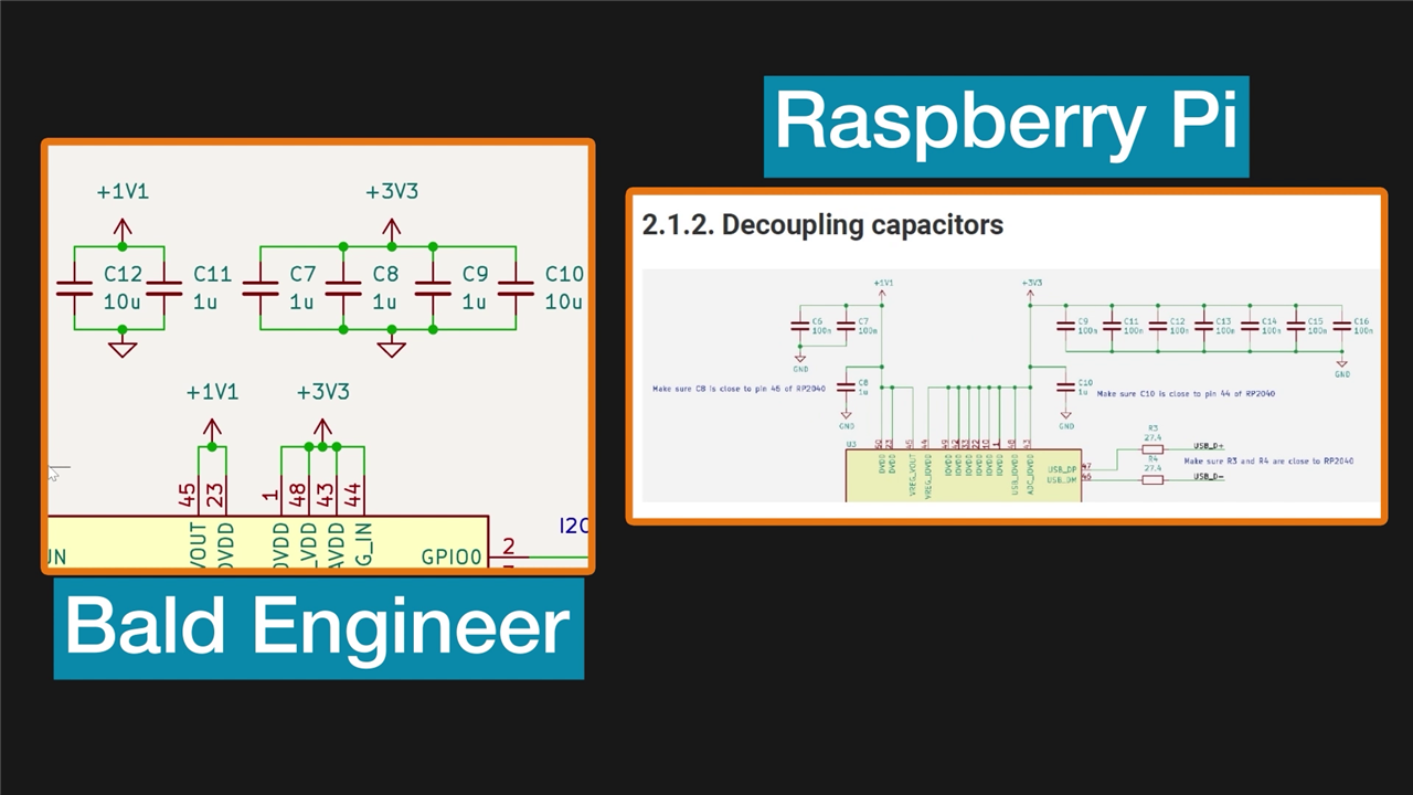
The example design here uses a linear regulator to drop USB's 5 volts down to 3.3 volts. Then, the RP2040's built-in linear regulator generates 1.1 volts for its logic core. James makes a point regarding the decoupling capacitors. The reference design in Raspberry Pi's "Hardware Design with RP2040" PDF shows many more capacitors than James used. The rationale is that he prefers larger 0603 and 0805 capacitors. So, there is not enough room for many 100 nanofarad caps. As explained in the article "The Myth of Three Capacitors," the multilayer nature of ceramic capacitors (MLCCs) already have multiple capacitors in parallel. (Reminder: James invites you to discuss this decision in the comments below!
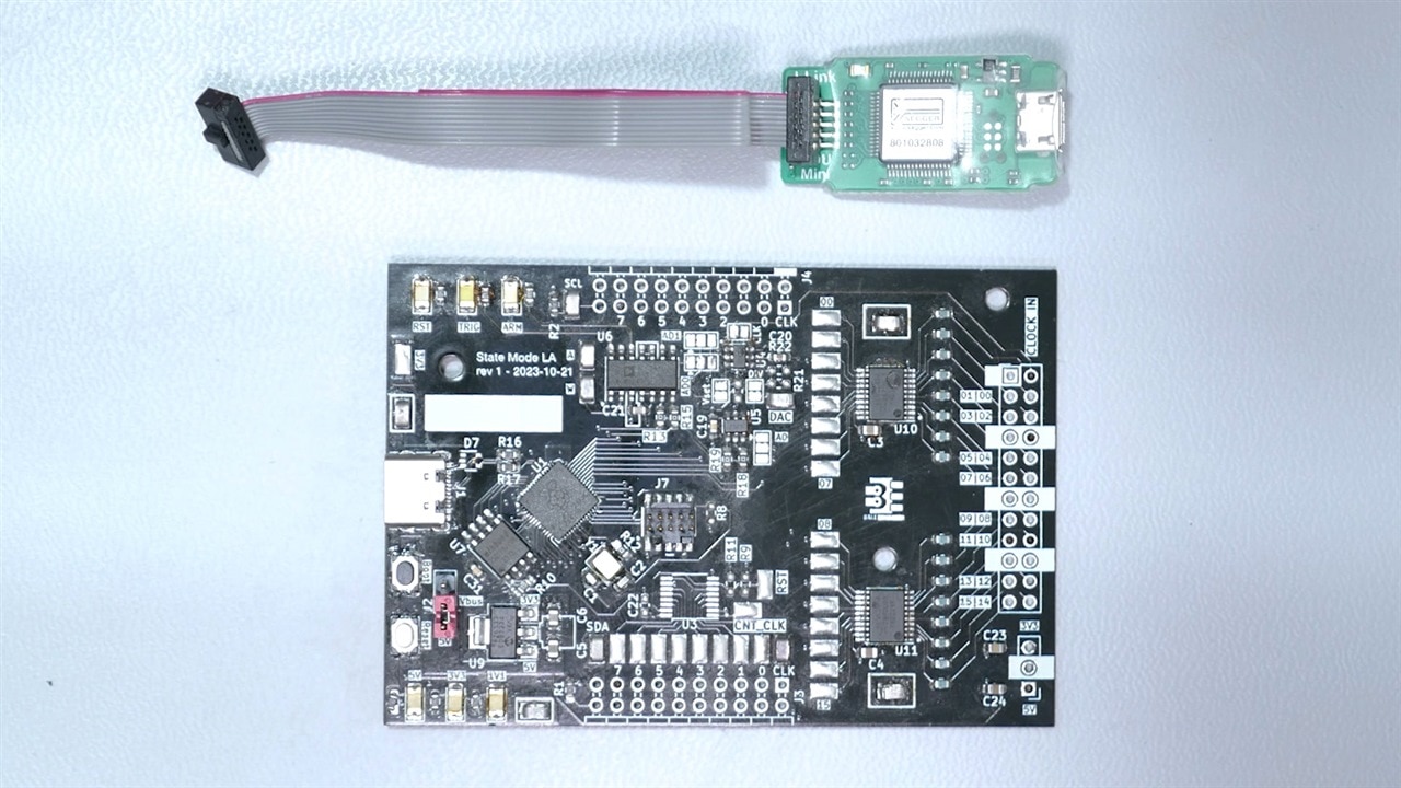
James uses an external programmer to load binary code into the custom RP2040 PCB's flash memory. In his case, he has a Segger J-LINK Mini (EDU edition). However, you can PicoProbe with another Pi Pico or Raspberry Pi's Pico Debug tool. Using an external programmer provides two advantages. First, they can access the RP2040's on-chip debugger so you can set breakpoints, step through code, and examine memory. Second, if the RP2040's USB bootloader does not work (or is not available), they offer another way to program the chip (or its EEPROM.)
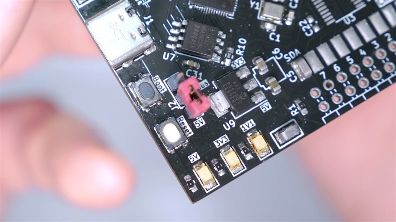
Raspberry Pi chose not to include a RESET button on the Pi Pico. This means you must hold the BOOTSEL button while cycling the USB connector to put the RP2040 into bootloader mode. James recommends both a RESET and BOOTSEL button in custom RP2040 PCB designs. That way, it is very easy to bootload the chip. And even if you do not plan to make use of the USB bootloader, at least consider putting solder jumpers so you can short them easily.
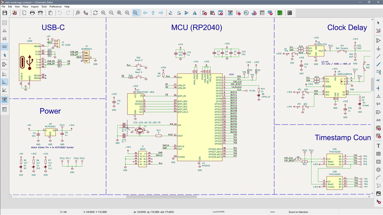
Keep in mind that James provided a link below to the project used in this video. You can use the design as a starting point for a custom RP2040 circuit. His design is based on the reference design from Raspberry Pi. However, the KiCad file contains part numbers (and Newark SKUs) for the actual parts he uses often. Except for the RP2040's QFN, he finds these parts are easier to solder than the 0402s and 0201s of the reference.
Turn-On
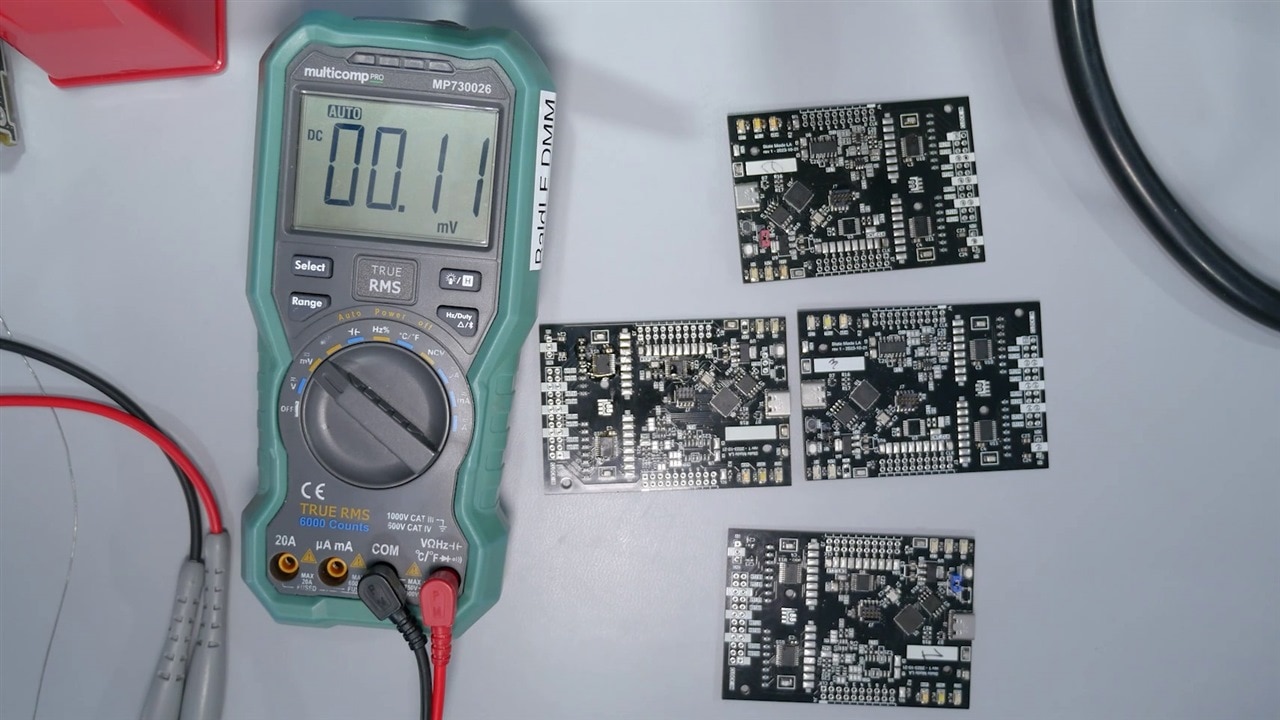
The last section of the video shows James turning on four copies of this custom RP2040 design. James always reflow solders at least two copies of a PCB. However, for this project, he did four because the PCBs are two different circuits. (The RP2040 area is the same. There are additional chips that have two different functions.) But that explanation must wait for a future video.

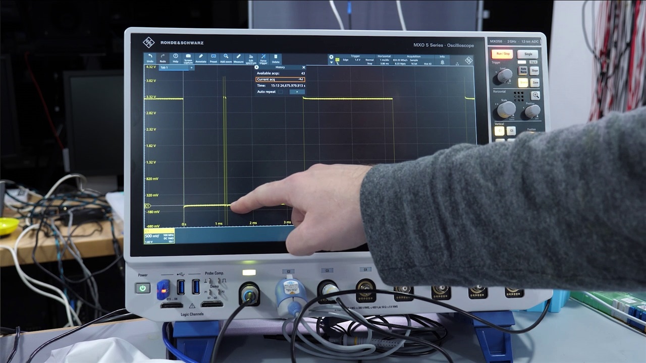
During this troubleshooting section, James finds a handful of solder issues. One issue was a solder blob that shorted the 1.1 volt and 3.3 volt rails together. James found the USB port also had shorted connections after Windows complained about a failed USB device. Another board had a very strange issue where it worked for a short time and then stopped responding to USB. Board #3 displayed a behavior where it would reboot into bootloader mode when programmed via SWD and by USB. The issue was, once again, some bad solder joints. James used an oscilloscope to watch the EEPROM's Chip Select (CS) line and then two of the data signals. One of the data signals was not connected.
After troubleshooting all of the issues on the custom RP2040 PCBs, James had two fully functional boards. His final demonstration was to run an I2C program on one of them. This program attempts to read from all valid I2C addresses to see if a device responds. Then, it prints an ASCII table over serial showing what it found. This scanner cannot identify the ICs, but it can at least tell if they are responding. And... they were! The board tested has three ICs on it, but only two are connected to the I2C bus.

James closes the video by commenting that creating and turning on a custom RP2040-based circuit can be easy. Then he adds, as long as you know where to look for the problems! Let us know what you think and if you have any RP2040 turn-on tips to share with the element14 Community!
Links and Downloads:
- Download Schematics and CAD Files!
- Pros and Cons of Low-Temp Solder Paste - Workbench Wednesdays 46
- Desoldering Wick Tips and Tricks with Superwick - Workbench Wednesdays 37
- Twin Lead Oscilloscope Probe Adapters (Ditch the Aligator Clips) - Workbench Wednesdays 73
- How to Decide Which Type of Flux to Use and How to Use Flux! - Workbench Wednesdays 59
- Why You Need a Raspberry Pi Pico Development Board by Shabaz - Workbench Wednesdays 70
- Pi Pico One-Click Installer for Windows and VSCode
- Hardware design with RP2040 (PDF)
- The Myth of 3 Capacitor Values
Bill of Material:
| Product Name | Quantity | Buy Kit |
|---|---|---|
| RP2040, 32-bit dual-core Arm Cortex-M0+ | 1 | Buy Now |
| PCB Test Point, S1751 Series, Surface Mount, Brass, Tin Plated Contacts | 5 | Buy Now |
| TACTILE SWITCH, SPST, 0.05A, 16VDC, SMD | 1 | Buy Now |
| Tactile Switch, SPST-NO, PTS810 Series, Top Actuated, Surface Mount, Oval Button, 600 gf | 1 | Buy Now |
| Flash Memory, Serial NOR, 128 Mbit, 16M x 8bit, SPI, SOIC, 8 Pins | 1 | Buy Now |
| CRYSTAL, 12MHZ, 18PF, SMD, 3.2MM X 2.5MM ROHS COMPLIANT: YES | 1 | Buy Now |
| Fixed LDO Voltage Regulator, 2.3V to 6V, 250mV Dropout, 3.3Vout, 1Aout, SOT-223-3 RoHS Compliant: Yes | 1 | Buy Now |
| USB Connector, 5A, 48V, 240W, 0.6mm, USB Type C, USB 2.0, Receptacle, 16 Positions | 1 | Buy Now |
| ESD Protection Device, TVS, 335 mW, 7 V, SOT-353, 5 RoHS Compliant: Yes | 1 | Buy Now |
| SMD Multilayer Ceramic Capacitor, 10 µF, 16 V, 0805 [2012 Metric], ± 10%, X7R, CL Series | 10 | Buy Now |
| SMD Multilayer Ceramic Capacitor, 27 pF, 50 V, 0603 [1608 Metric], ± 10%, C0G / NP0 | 2 | Buy Now |
| SMD Chip Resistor, 5.1 kohm, ± 5%, 100 mW, 0603 [1608 Metric], Thick Film, General Purpose | 2 | Buy Now |
| RP2040 Xiao | 1 | Buy Now |
| Pi Pico Debug Probe | 1 | Buy Now |
| PTS525 - Hand solderable SMT Switch | 1 | Buy Now |
| J-Link Mini EDU | 1 | Buy Now |

-

misaz
-
Cancel
-
Vote Up
0
Vote Down
-
-
Sign in to reply
-
More
-
Cancel
-

baldengineer
in reply to misaz
-
Cancel
-
Vote Up
0
Vote Down
-
-
Sign in to reply
-
More
-
Cancel
Comment-

baldengineer
in reply to misaz
-
Cancel
-
Vote Up
0
Vote Down
-
-
Sign in to reply
-
More
-
Cancel
Children