


Introduction
It can be interesting trying to come up with user interfaces for equipment. I had a conversation with some friends recently, who were discussing how germs and viruses could be on lift/elevator buttons and then transferred to the fingers. I expressed surprise, since I thought it was normal to use the back of the hands and the knuckles. Another friend mentioned that his procedure was to use his elbow to press the button.
There are all sorts of use-cases for push-buttons of course, and over time other methods may take over. Room lighting could be controlled by light level and inferring intent; no need for physical controls at all one day perhaps. Systems could learn when things should be switched on or off. Systems could be overridden by voice command. Voice control is already prevalent, it is now not uncommon to see people controlling their home electronics using Internet-connected devices operating as virtual assistants.
There are some great technologies for creating user interfaces, and I explored one a while back (see Virtual Reality, Leap Motion, and Controlling Things! - Getting Started Guide ) which relies on small cameras to capture 3D information which the computer processes to figure out the position of hands and the gesture being performed. It was really cool technology but needed an x86 processor. There are other optical methods too of course, some that won’t require as much heavyweight processing.
The growth of 32-bit microcontrollers such as ARM Cortex-M means that there is a lot of power available for doing digital processing for non-traditional sensors! This project uses an ARM-provided library for digital signal processing, in order to extract useful information.
For this project I decided to explore capacitance based methods, since I had a Texas Instruments capacitance measuring integrated circuit from an old review (see Texas Instruments FDC2214 Capacitance to Digital - Review ). I’d been fascinated at how sensitive it was, and had used a large metal plate to sense someone walking past, or a hand wipe in the air. The measurements were so granular that the chip could detect humidity changes between capacitor plates! I really wanted to explore the chip further and see if I could develop a set of contactless buttons, the idea being to tap virtual buttons in mid-air.
Check out the 1-minute video to see the result! The air-tap operation means that the surface of the unit need never be touched, for selection or perhaps numeric entry, indoors or outdoors.
How does it work?
The heart of the system is an FDC2214 Capacitance to Digital Converter part from Texas Instruments which can measure capacitance at an extremely high resolution. The capacitor-under-test is assembled into a resonant circuit using a parallel inductor, and the TI chip measures the oscillation frequency. If the capacitance changes then the frequency changes. The TI chip is connected to a microcontroller which can read the frequency (and therefore indirectly the capacitance) for up to four resonant circuits, and it can take measurements hundreds of times a second.
In order to bring the human user into the system, the capacitance needs to be modified in some way as the user attempts to air-touch a virtual button. I decided to implement a ‘self capacitance’ method, whereby one end of the resonant circuit is attached to a metal plate. A nearby human finger will create a capacitance with the body, and the body will have a capacitance to ground. Similarly the metal plate will have some capacitance to ground. The change in capacitance due to the finger presence will be small, but measurable. With traditional capacitive touch sensors the measurement method isn’t as granular or low-noise, however the resonant circuit frequency measurement method is! The presence of a finger should cause a noticeable difference to occur in the measured capacitance even at some distance away.
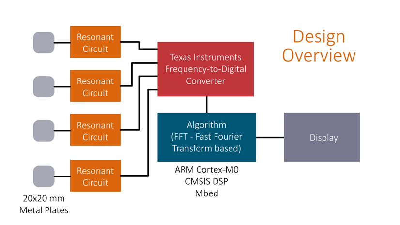
The next step was to figure out how to use the raw readings to detect air-taps. I decided to use an ARM DSP library to perform a fast fourier transform (FFT) on the stream of capacitance measurements. The FFT procedure is used to extract frequency components present in the incoming stream of data values. The result of this is a set of frequency-related buckets. By using the contents of a bucket, the system can be used as kind of a filter, to remove constant or slow-changing capacitance values from the analysis. This was great – now the system could more reliably detect the rapid motion of a hand moving toward or away from the metal plate! It would also near-eliminate all construction issues, since capacitance changes are output from the algorithm, not static values that would be related to how the project was built or where it was physically located.
Another problem was how to know which button was being pressed, since all of the sensors will detect a capacitance change from a distance. That was easy to solve by comparing the bucket value across all of the sensors and choosing the largest one.
Finally I needed to decide on the data sampling rate, which is configurable with the Texas Instruments chip; at higher sample rates the measurements are less granular, but on the other hand a lower sampling rate means that I cannot distinguish fast hand movements. I experimented a little with the values until I was happy with the result.
To implement this system in code, I created two classes; one to support measurements from the TI chip, and another to handle the data analysis. Taking measurements is as simple as:
Fdc fdc; // create the fdc object
fdc.reset();
fdc.read();
value[channel] = fdc.getDat(channel); // object returns the value read for any sensor channel (1-4)
The analyzer is just as easy to use:
Analyzer analyzer[4]; // create four analyzer objects, one for each sensor channel
Analyzer[channel].insert(value); // push the value into the analyzer object
activityLevel = analyzer[channel].getActLevel();
The activityLevel variable in the code snippet above indicates the amount of motion detected, i.e. if a sensor is being air-tapped.
The Mbed system was used to code the project. For an explanation of that, see Working with FRDM Boards and ARM mbed
Source Code
The source code is available on github.
Construction and Schematic
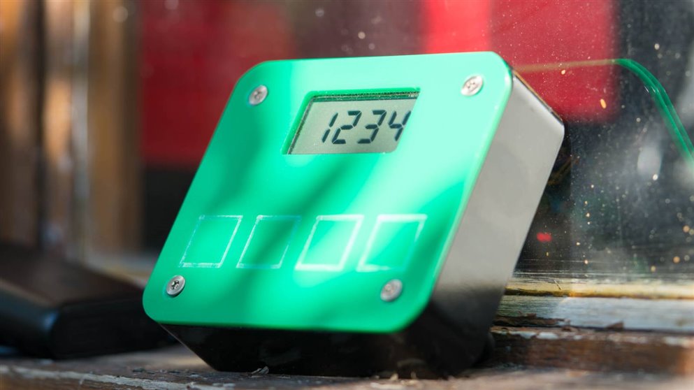
I used guesswork to find suitable capacitor plate sizes. I went with 20x20 mm aluminium plates, each separated from the other by 6mm. That means that each button center is 26 mm from the next button center. That’s not much more than existing typical outdoor push-buttons, so I think the solution could be retrofitted. To test that, I looked up an outdoor keypad with a 4x3 matrix – it had buttons separated by 19 mm. Since I wanted to try as realistic a setting as I could manage, the demonstrator model was built using an existing outdoor keypad enclosure (intended for 4x3 outdoor keypads) made of metal. The front panel was 3mm thick acrylic sheet. I used a reflective LCD screen since that would be visible outdoors, although it would need a protective clear cover.
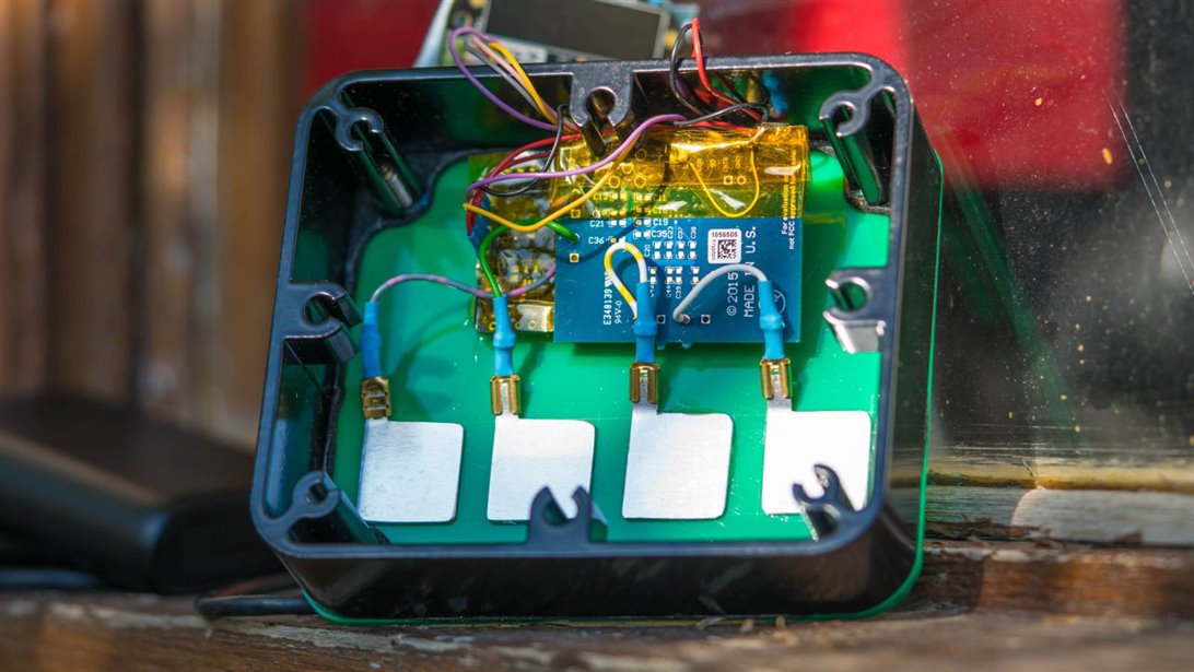
A practical design might use shapes etched in copper on a PCB, but I used aluminium plate for now, so I could move them around if I got the separation or sizes guessed wrong.
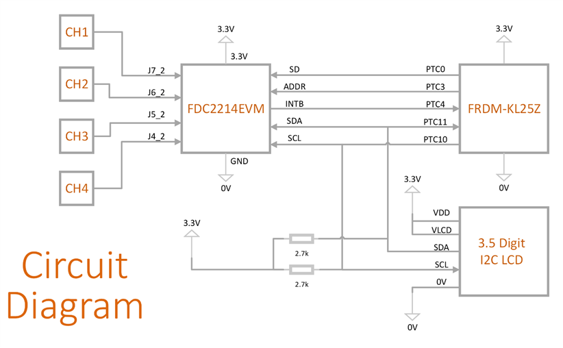
For the microcontroller board, I used an old Freescale/NXP FRDM-KL25ZFRDM-KL25Z board, but nearly any ARM Cortex-M chip could be used, since that FRDM board has a basic Cortex-M0 and not a lot of resources.
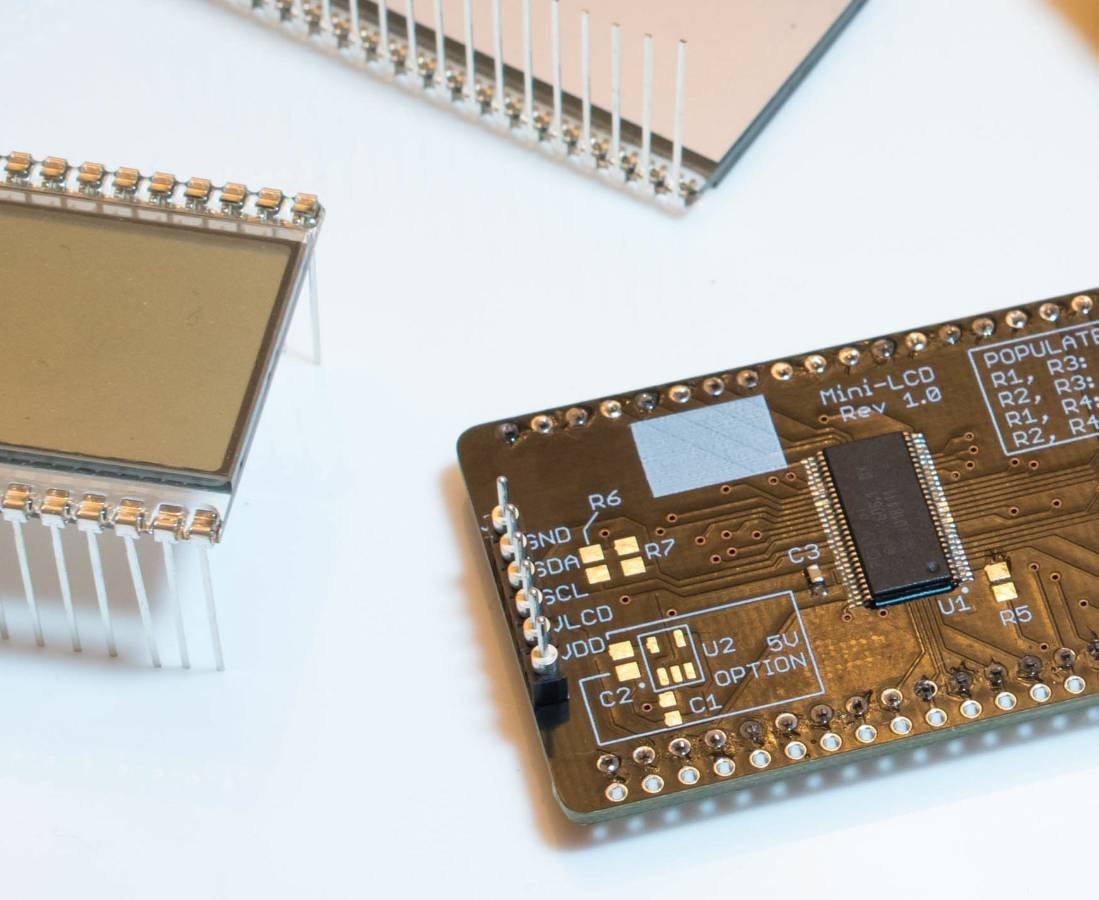
The LCD screen was an earlier project: Building a 3.5 Digit Low Power LCD Module . It uses a piece of LCD glass from Aliexpress, combined with an I2C LCD driver chip from NXP. I’ve built up several of these displays, they come in handy for prototypes. I decided to make half a dozen of these at a time (to save on shipping costs), it then costs less than £5 (approx $7 USD) each.
Testing it
Although not a lot of testing has been done so far, I did want to try it outdoors, just to confirm that it could operate in an example environment where existing outdoor buttons could be required. I propped it up at a suitable height on a window ledge, although in reality it may be screwed to a wall, and tested using a USB power bank. I also tested indoors, powered from a USB phone charger, and from a laptop USB supply. It seems to behave itself, although I’m sure it could be fine-tweaked further to suit specific applications. The video at the top of this blog post shows the outdoor result.
Summary
It was really nice to see that air-tapping virtual buttons could be viable using this capacitance method. I’d like to build a multi-chip expandable system that could be assembled to form 8- or 12- or 16- sensor interfaces, for complete numeric entry for instance. For more mission-critical data entry, an OK or CANCEL air-tap button could be used too.The TI FDC2214 part is tiny (0.5mm pitch QFN style), but I think it’s worth the effort trying to solder it on a custom PCB. It costs just under $3 USD in 1000 quantity, so it's cheaper than mechanical push-buttons too.
I was happy to see that the project can work outdoors too, and it adapts to different capacitance situations since the software actively looks for faster changes that are representative of a real human trying to air-tap the buttons.
If you would like to build this project too, the circuit diagram showing the connections between the boards is shown in the blog post. The source code is available on github. Follow the steps here to program the board: Working with FRDM Boards and ARM mbed
Work is underway to build a custom PCB for this project. For a log of that activity, see the comments below.
Thanks for reading!
Top Comments
-

navadeepganeshu
-
Cancel
-
Vote Up
+1
Vote Down
-
-
Sign in to reply
-
More
-
Cancel
-

shabaz
in reply to navadeepganeshu
-
Cancel
-
Vote Up
+1
Vote Down
-
-
Sign in to reply
-
More
-
Cancel
-

navadeepganeshu
in reply to shabaz
-
Cancel
-
Vote Up
+1
Vote Down
-
-
Sign in to reply
-
More
-
Cancel
Comment-

navadeepganeshu
in reply to shabaz
-
Cancel
-
Vote Up
+1
Vote Down
-
-
Sign in to reply
-
More
-
Cancel
Children