element14 Community
element14 Community
    Register Log In
  • Site
  • Search
  • Log In Register
  • About Us
  • Community Hub
    Community Hub
    • What's New on element14
    • Feedback and Support
    • Benefits of Membership
    • Personal Blogs
    • Members Area
    • Achievement Levels
  • Learn
    Learn
    • Ask an Expert
    • eBooks
    • element14 presents
    • Learning Center
    • Tech Spotlight
    • STEM Academy
    • Webinars, Training and Events
    • Learning Groups
  • Technologies
    Technologies
    • 3D Printing
    • FPGA
    • Industrial Automation
    • Internet of Things
    • Power & Energy
    • Sensors
    • Technology Groups
  • Challenges & Projects
    Challenges & Projects
    • Design Challenges
    • element14 presents Projects
    • Project14
    • Arduino Projects
    • Raspberry Pi Projects
    • Project Groups
  • Products
    Products
    • Arduino
    • Avnet Boards Community
    • Dev Tools
    • Manufacturers
    • Multicomp Pro
    • Product Groups
    • Raspberry Pi
    • RoadTests & Reviews
  • Store
    Store
    • Visit Your Store
    • Choose another store...
      • Europe
      •  Austria (German)
      •  Belgium (Dutch, French)
      •  Bulgaria (Bulgarian)
      •  Czech Republic (Czech)
      •  Denmark (Danish)
      •  Estonia (Estonian)
      •  Finland (Finnish)
      •  France (French)
      •  Germany (German)
      •  Hungary (Hungarian)
      •  Ireland
      •  Israel
      •  Italy (Italian)
      •  Latvia (Latvian)
      •  
      •  Lithuania (Lithuanian)
      •  Netherlands (Dutch)
      •  Norway (Norwegian)
      •  Poland (Polish)
      •  Portugal (Portuguese)
      •  Romania (Romanian)
      •  Russia (Russian)
      •  Slovakia (Slovak)
      •  Slovenia (Slovenian)
      •  Spain (Spanish)
      •  Sweden (Swedish)
      •  Switzerland(German, French)
      •  Turkey (Turkish)
      •  United Kingdom
      • Asia Pacific
      •  Australia
      •  China
      •  Hong Kong
      •  India
      •  Korea (Korean)
      •  Malaysia
      •  New Zealand
      •  Philippines
      •  Singapore
      •  Taiwan
      •  Thailand (Thai)
      • Americas
      •  Brazil (Portuguese)
      •  Canada
      •  Mexico (Spanish)
      •  United States
      Can't find the country/region you're looking for? Visit our export site or find a local distributor.
  • Translate
  • Profile
  • Settings
Merry Boxes & LEDs
  • Challenges & Projects
  • Project14
  • Merry Boxes & LEDs
  • More
  • Cancel
Merry Boxes & LEDs
Blog Motion Sensor Issues, continued
  • Blog
  • Forum
  • Documents
  • Events
  • Polls
  • Files
  • Members
  • Mentions
  • Sub-Groups
  • Tags
  • More
  • Cancel
  • New
Join Merry Boxes & LEDs to participate - click to join for free!
  • Share
  • More
  • Cancel
Group Actions
  • Group RSS
  • More
  • Cancel
Engagement
  • Author Author: ntewinkel
  • Date Created: 5 Jan 2019 11:39 PM Date Created
  • Views 3299 views
  • Likes 8 likes
  • Comments 18 comments
  • wifi
  • merryboxesledsch
  • xmas
  • motion
  • arduino
  • wemos
  • sensor
Related
Recommended

Motion Sensor Issues, continued

ntewinkel
ntewinkel
5 Jan 2019
image

Merry Boxes & LEDs

Enter Your Project for a chance to win a Maker Tool Kit, an Oscilloscope Grand Prize for the project that brings the Most Joy to the Heart, and Gift to Gives!

Back to The Project14 homepage image

Project14 Home
Monthly Themes
Monthly Theme Poll


I spent a fair bit of time today trying to figure out what was going on with the motion sensor on Tree 1.


I tried a few things, starting with switching the Wemos itself, and it turns out that when I use the Wemos from the working tree, Tree 1 does work properly.

So it's not the tree itself or the wiring around it, or the PIR sensor. That's a good thing.


Here is a video of me testing the PIR sensor directly, powered by the breadboard power supply. It works nicely.

You don't have permission to edit metadata of this video.
Edit media
x
image
Upload Preview
image


Then I thought maybe I had shorted something out and broken the Wemos board, but further testing showed that switching input pins made no difference, and I could set the inputs directly to GND or to 3.3 volts, and it would read correctly.


The motion sensor does require 5v input power, with minimum of 4.5v, so I thought I'd compare the two Wemos boards. They have pretty much identical voltage showing at the 5v pin. Actually a little low - 4.69v, when powered from my Mac. Yet one works, and the other doesn't!

So I decided to directly power the board with a USB charger instead, but alas, it still did not work.


A video showing my pain:

You don't have permission to edit metadata of this video.
Edit media
x
image
Upload Preview
image


The sketch running on the Wemos is just one that does serial coms for debug, and checks for PIR input. However, if you look carefully the PIR sensor wire is only going to the multimeter, and thus the GPIO input is always just 10k to gnd. In short - the Wemos is only used to power the PIR sensor at this point.


As you can hear me say in the video, I was thinking of just giving up on the motion sensors altogether and just using a pushbutton instead. That might actually make more sense in real life use anyway.


The other thought I had is that PIR sensors can be sensitive to interference (so they say on the internets, it may or may not be true) - maybe this difficult Wemos board was causing more interference than the other?


Then I had a thought... The official Raspberry Pi power supply provides a slightly higher 5.1v, maybe that gives the PIR sensor that little extra edge to work?

And lo and behold! it works! Kinda surprised me at this point, actually.


So it appears that, annoyingly enough, the PIR sensor should probably not be powered by the Wemos 5v pin. I thought it was a direct connection to the USB input, but I wonder if there's something else in the way.

In general, the whole setup should probably provide power to the tree and the sensor separately from the power supplied to the Wemos. But that's beyond the scope of this project.


So I will reassemble Tree 1, upload the Connected Trees sketch back on it, add some nail polish to the connections, and then make it all look pretty... and I'll make sure to use the RPi power adapter for the difficult Wemos.


I'm not entirely happy with the finicky results, but for now this will have to do. If we do end up using this "in real life" next Christmas, I'll probably just switch it to use pushbuttons instead.


Here's a picture of the solder joints with dollar-store nail polish protecting the joins. I ended up buying a pack just for the red and green in it, and it turns out the rainbow of colours works well here!


image


Edit:

Here is a quick sketch of the schematic that I used to keep things straight in my mind while soldering. The input pins have since changed a little (pls see the source code for the updated numbers).

image

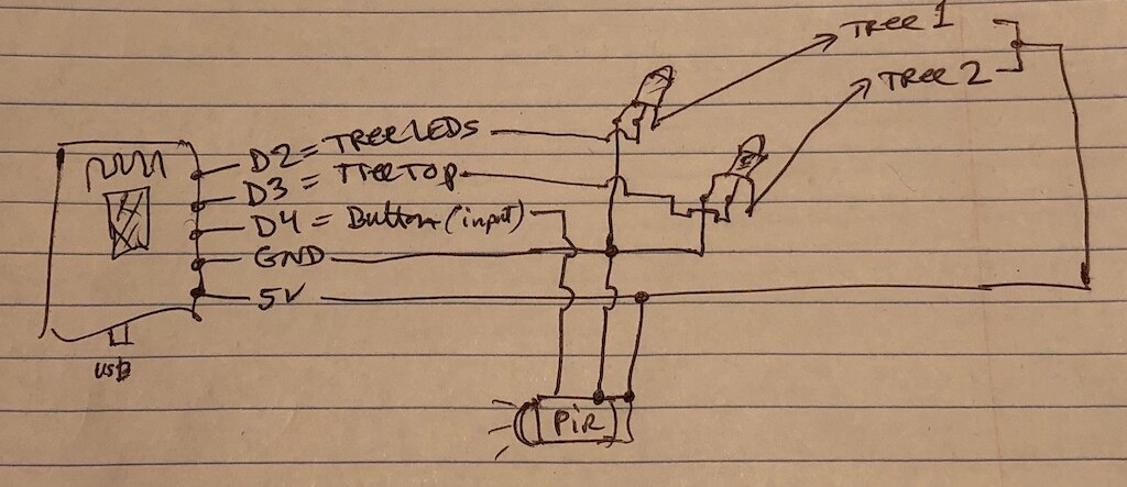
Note that in this sketch "Tree 1" and "Tree 2" refers to the two wires going to the trees, not to separate trees. I probably should have written it more clearly, like "Main Tree" and "Tree top LED". The transistors are basic NPN 2N2222a.


Cheers,

-Nico


Previous posts:

Connected Christmas Trees

Assembling the Trees

Finally! Two Trees Assembled

Two Trees by a Tree

Connecting the Tree to the Internet

Motion Sensor on Wemos

Trees! one with motion sickness...


Next posts:

The Connected Trees are Working!

Merry Boxes - A Project Within a Project

Connected Christmas Trees - Finished!

  • Sign in to reply

Top Comments

  • mcb1
    mcb1 over 6 years ago +5
    Good work sorting out the issues. On the link you sent for the PIR, it appears there is a diode in series with the +ve input, which then goes to what looks like a regulator. I found this here https://www…
  • mcb1
    mcb1 over 6 years ago in reply to mcb1 +4
    There is an interesting note here about the 'boot' time. https://forum.arduino.cc/index.php?topic=538734.0 He has also managed to reduce the 10sec delay. Mark
  • mcb1
    mcb1 over 6 years ago in reply to ntewinkel +4
    Not sure if I want to keep using the PIR sensors for these trees though Perhaps those microwave sensors that fmilburn suggested here LS Cubed: Little Sister Security System Mark
  • mcb1
    mcb1 over 6 years ago in reply to ntewinkel

    PIR are Passive Infra Red energy detecting, and the lens on the front tends to concentrate the energy into collection areas. It senses the difference in background Infra Red and in theory anything that emits more.


    The microwave units have a requirement to be spaced away from a metal or conductive surface, and I haven't had the opportunity (okay .. time) to do any experiments with using reflectors to improve or shape the pattern.


    Any normal plastic box should be enough, but your nice CNC routed battery enclosure might also work image


    Mark


    I'm rapidly running out of time to get my trees modified and connected in time.

    Maybe mine will be after the deadline image

    • Cancel
    • Vote Up +1 Vote Down
    • Sign in to reply
    • More
    • Cancel
  • fmilburn
    fmilburn over 6 years ago in reply to ntewinkel

    The githib link I posted above has working code for the “radar” and PIR.  In the link to the post that Mark gave above I describe and there are even further links to how the radar can detect through some objects under some circumstances.  Hope that helps...

    • Cancel
    • Vote Up +3 Vote Down
    • Sign in to reply
    • More
    • Cancel
  • ntewinkel
    ntewinkel over 6 years ago in reply to fmilburn

    Thanks Frank!


    Yes, mine look exactly the same image

    In my distracted state I somehow missed the part where you and Mark mentioned that you're using the radar sensor instead of PIR. That might be the ultimate better solution for this project.

    Can the radar module work when hidden? or does it have an eye like the PIR sensors that needs to be exposed?


    ps, (some of) the oddities I ran into was indeed a Wemos specific thing - D3, D4, and D8 have external resistors added already. That explains why D3 was constantly reading high even when the sensor or button was disconnected!


    Thanks,

    -Nico

    • Cancel
    • Vote Up +3 Vote Down
    • Sign in to reply
    • More
    • Cancel
  • fmilburn
    fmilburn over 6 years ago in reply to ntewinkel

    Hi Nico,


    I posted all the code for that project here and the sketches have the pin connections documented, including PIR.  The folder with just the final code for the RCWL-0516 is here.  You may have different pins brought out or maybe the labels on the board are different.  My boards look like this:

    image

    • Cancel
    • Vote Up +3 Vote Down
    • Sign in to reply
    • More
    • Cancel
  • ntewinkel
    ntewinkel over 6 years ago in reply to fmilburn

    Ah! That's good to know, thanks Frank!


    Out of curiosity, which GPIO pin did you use for it?


    I'm thinking for my next step to use the same pins that the Witty WiFi uses for its built-on button and LEDs, just to rule out any pin specific oddities I might be missing.


    -Nico

    • Cancel
    • Vote Up +1 Vote Down
    • Sign in to reply
    • More
    • Cancel
>
element14 Community

element14 is the first online community specifically for engineers. Connect with your peers and get expert answers to your questions.

  • Members
  • Learn
  • Technologies
  • Challenges & Projects
  • Products
  • Store
  • About Us
  • Feedback & Support
  • FAQs
  • Terms of Use
  • Privacy Policy
  • Legal and Copyright Notices
  • Sitemap
  • Cookies

An Avnet Company © 2025 Premier Farnell Limited. All Rights Reserved.

Premier Farnell Ltd, registered in England and Wales (no 00876412), registered office: Farnell House, Forge Lane, Leeds LS12 2NE.

ICP 备案号 10220084.

Follow element14

  • X
  • Facebook
  • linkedin
  • YouTube