


For the Hack the Holidays Competition where in i made a Project NorthPole Navigator I proposed to make an earring with LED lights what would glow faster when closer to Hidden Christmas gift. Sadly the PCB came in late and so i had to make do with an alternative PCB to make the Finder, although not in an earring format. But I never could stand the fact that the PCB was lying there. So again this Spring clean i brought it back to life.
But i changed the working as a Novelty earring which would show same LED pattern on both ears. In the Hack the holiday's contest, i was relying on the RSSI of a BLE tracker on the gift, and it was assumed that both the Earring would get similar RSSI and would glow similarly, but in this case i had to rely on Enhanced Shock Burst protocol by Nordic to keep the two NRF52832 chips synched to show the same LED pattern.
Spring Clean Theme
When i went though the projects i realized i had many to spring clean, Some of them were stretch goal, some were actually paused and never resumed, some were to fix older projects. This competition gave me good motivation to complete more than few projects and so here is the final list including this one
- Completing the Christmas Tree Earring after 6 Months
- Building a Low Power keyboard for Future Projects
- Replacing an Aging Cochlear Implant Battery Carry Box
- BreatheSafe - Hackathon Project to Real Device: DIY AQI Tracker for Runners
- Reviving a Kids’ RFID Music with Lights Jukebox
This competition also allowed me to experiment and learn video editing using KDenLive, Mermaid Diagrams and The Content presentation.
The Requirements
- Battery Powered NRF52832 MCU with Chip Antenna - To make the PCB as small as possible
- Christmas tree design - It should not be a one flat PCB, but should have segments which can move or twist with respect to each other
- 12 LEDs which should be visibly synchronized
- Multiple LED Patterns choice via Push button
Schematics and PCB


The Plan was to cut the PCB and assemble them in pieces using my MHP-50 Soldering plate. Twelve WS2812B RGB LEDs is laid out in Four groups from bottom to top: 5 (base ring), 3 (middle), 2 (upper), 2 (star at the top)
The sync problem
Syncing two WS2812B strips was easier said than done. I initially started with two NRF Development board syncing the 4 onboard LED, then moved to syning one RGB LED, but as the pattern became faster and more leds, problems started to appear. Option one: transmit the pixel data over radio every frame. At 12 LEDs × 3 bytes = 36 bytes per frame and 30 Hz, that is 32 kbps, which the 2 Mbps ESB radio handles with its eyes closed. But this approach has no resilience to packet loss -- one dropped frame and one earring glitches while the other carries on.
Option two, and the one used here: both boards run the same deterministic animation code and you just need to keep them pointed at the same tick_ms. No pixel data is transmitted at all. A dropped packet means the slave coasts on its last known position. The visual effect degrades gracefully rather than glitching
The key constraint this places on the pattern code: every pattern must be fully deterministic from tick_ms alone. No PRNG state, no accumulated phase variable, nothing that would drift between two boards that started at the same value. Each call to a pattern function must produce exactly the same output for the same input, every time, on any board. That is what "group-wise deterministic" means in the code.

What gets transmitted
The entire radio payload is six bytes:
byte[0]    seq_num   -- wrapping uint8_t drop-detection counter
byte[1]    pat_idx   -- currently active pattern (0..13)
byte[2..5] tick_ms   -- master wall-clock ms, little-endian uint32_t
That is it. No pixel data, no colour buffer, no checksums beyond what ESB DPL provides natively. The seq_num is there purely to count how many frames the slave missed. pat_idx lets the user switch patterns on the master and have the slave follow immediately. tick_ms is the shared time reference.
Radio config: ESB Dynamic Payload Length, pipe 0, address E7:E7:E7:E7:E7, 2 Mbps.
Master main loop
The master owns the time reference. Every 33 ms (30 Hz):
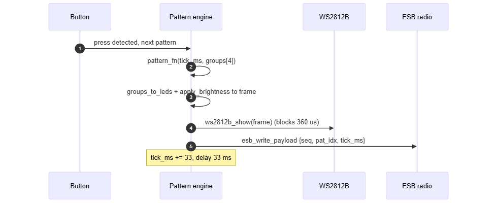
In code, the main loop body looks like this:
k_patterns[m_pat_idx].fn(m_tick_ms, m_groups);   // render
groups_to_leds(m_groups, m_leds);
apply_brightness();

ws2812b_show(m_frame);                            // drive local strip

m_tx_payload.data[ESB_PKT_SEQ_IDX]       = seq;
m_tx_payload.data[ESB_PKT_PAT_IDX]       = (uint8_t)m_pat_idx;
m_tx_payload.data[ESB_PKT_TICK_IDX + 0u] = (uint8_t)(m_tick_ms >>  0);
m_tx_payload.data[ESB_PKT_TICK_IDX + 1u] = (uint8_t)(m_tick_ms >>  8);
m_tx_payload.data[ESB_PKT_TICK_IDX + 2u] = (uint8_t)(m_tick_ms >> 16);
m_tx_payload.data[ESB_PKT_TICK_IDX + 3u] = (uint8_t)(m_tick_ms >> 24);
nrf_esb_write_payload(&m_tx_payload);

seq++;
m_tick_ms += FRAME_MS;
nrf_delay_ms(FRAME_MS);
Slave tick extrapolation
The slave does not maintain its own wall clock. Instead, every time a packet arrives, the ESB ISR latches two things: the master's tick_ms from the packet and the current value of the ARM Cortex-M4 DWT cycle counter at that exact moment.
void nrf_esb_event_handler(nrf_esb_evt_t const *p_event)
{
    // drain the RX FIFO ...
    m_anchor_ms  = tick_ms;
    m_anchor_cyc = dwt_timer_now_cyc();   // DWT->CYCCNT snapshot
    m_pat_idx    = pat;
    m_synced     = true;
}
In the main render loop, when it is time to compute the current frame, it extrapolates forward from that anchor:
uint32_t tick = m_anchor_ms + dwt_timer_ms_elapsed(m_anchor_cyc);
k_patterns[m_pat_idx].fn(tick, m_groups);
dwt_timer_ms_elapsed() is: return (DWT->CYCCNT - anchor_cyc) / 64000u;
The CPU runs at 64 MHz, so dividing the cycle count by 64,000 gives you milliseconds. The math handles counter wraparound correctly, and you don't need a separate timer peripheral DWT is built into every Cortex-M4 and just needs the TRCENA bit enabled in CoreDebug.
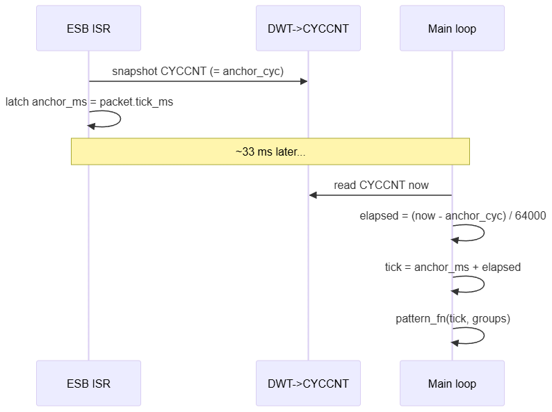
If a packet is dropped, the anchor does not update. The DWT counter keeps advancing, so dwt_timer_ms_elapsed() keeps growing, and the slave's rendered tick continues smoothly forward. The slave never stalls or freezes on a missed packet.
The rendering pipeline
Both boards run this identical pipeline:
tick_ms
|
v
pattern_fn(tick_ms, groups[4]) -- computes one rgb_t per group
|
v
groups_to_leds(groups, leds[12]) -- each LED inherits its group colour
|
v
apply_brightness(leds, frame[36]) -- scale R,G,B by BRIGHTNESS_PCT / 100
|
v
ws2812b_show(frame) -- PWM burst to the WS2812B strip
The 12 LEDs are divided into 4 concentric rings:
| Group | LEDs | Position |
|---|---|---|
LED_GROUP_TREE3 |
5 | base / widest ring |
LED_GROUP_TREE2 |
3 | middle ring |
LED_GROUP_TREE1 |
2 | upper ring |
LED_GROUP_STAR |
2 | star at the top |
Every pattern operates on those 4 groups. They never see individual LEDs. groups_to_leds() does the fan-out. This also means you can add more LEDs to a group later and all the patterns automatically light them the right colour.
There are 14 patterns total, all fully deterministic from tick_ms
| # | Pattern | What it does |
|---|---|---|
| 1 | rainbow_wipe |
Hue advances 2 per frame, spread across groups |
| 2 | christmas_string |
Festive palette with per-group breathing |
| 3 | christmas_static |
Static alternating green tree + yellow star |
| 4 | christmas_chase |
Palette shifts one slot every 250 ms |
| 5 | group_cascade |
Groups illuminate in sequence, 8 s cycle |
| 6 | y_fall |
Colour waterfall top -> bottom, 3 s period |
| 7 | y_rise |
Colour waterfall bottom -> top, 3 s period |
| 8 | x_sway |
Sine wave sways horizontally |
| 9 | star_pulse |
Star pulses warm white; tree breathes dim green |
| 10 | twinkle |
Deterministic sparkle via Knuth multiplicative hash |
| 11 | snow_drop |
Snowflakes fall from star to base |
| 12 | heartbeat |
All groups pulse red, double-beat, 1 s period |
| 13 | radial_from_star |
Gaussian rings expand from star, 2.5 s period |
| 14 | off |
LEDs off |
These ideas was ideated through AI. I am not that creative. Also the code for each of these animations was also done though AI, because it would take a lot of time.
The WS2812B driver
WS2812B needs a 800 kHz signal where a 1 bit is a ~812 ns HIGH pulse and a 0 bit is a ~375 ns HIGH pulse. The nRF52's PWM peripheral handles this without needing SPI tricks or bit-banging.
Config: PWM clock 16 MHz, TOP = 20. That gives a 1.25 µs period = 800 kHz. Each bit maps to one 16-bit sequence value. The WS2812B byte order is G, R, B (green first, which surprises people).
12 LEDs × 3 bytes × 8 bits = 288 duty words + 40 reset slots (50 µs LOW to latch the frame)
ws2812b_show() is a blocking call -- it fills the sequence buffer, starts the PWM peripheral, and waits for the DMA to drain. Total time: about 360 µs for 12 LEDs.
ESB payload length: the silent overrun
Previously, we tried sending a 36-byte RGB buffer over the radio. This created some unexpected behaviour. The ESB library defines NRF_ESB_MAX_PAYLOAD_LENGTH as a compile-time constant and uses it to size an internal struct: The SDK default is 32 bytes. My 38-byte frame caused three things to silently break at once: So i had to change the size along with the following compiler flags
CFLAGS   += -DNRF_ESB_MAX_PAYLOAD_LENGTH=64
ASMFLAGS += -DNRF_ESB_MAX_PAYLOAD_LENGTH=64
What works and what does not
What works:
- Both earrings run visually identical animations at 30 Hz
- Pattern switching on the master propagates to the slave within one frame
- Dropped frames are invisible in practice; the slave extrapolates smoothly
- All 14 patterns are deterministic; they look identical on both boards
What does not, or what is not done yet:
- Slave still uses an independent 33 ms sleep, so it can lag up to 35 ms (visible on high-speed camera)
- No render-on-receive yet; that is the biggest improvement waiting to be implemented
- No bidirectional link; slave cannot report its stats or signal battery low
- Build requires two separate Makefile invocations (master and slave)
Video Demo

The Code
The code for this project can be found here: https://github.com/arvindsa/xmas-tree-earring