


|
BDTH6159 Amusement Park needs predictive maintenance. They have a number of rides that have to be kept safe and in good condition. This tale protects Tommy from mechanical mishaps. That is: if Ray manages to find him. The project is an Arduino MKR Accelerometer that will send vibration info to the Arduino Cloud. The amusement park staff uses this to spot trends and changes in the gearboxes, motors and axles of the rides.
The artwork in this story is an ode to Benoît Sokal. Comic Artist and Designer of the Syberia game. |

Theme park rides are an excellent example of equipment that needs maintenance. There's a number of industrial strength motors, bearings, gears and movements involved. Those are the usual candidates for vibration-based monitoring. The rides are accessible to the public, so there are additional incentives (and laws) to make sure they are well maintained. And that potential failures are detected before they cause harm. Regulations in industry are strict. In theme parks, they are an order of magnitude more strict.
Monitoring anomalies in the components pays off. I've recently done a road test on the subject: Calculate Acceleration Energy, to drive Maintenance Decisions. In this tale, I try to apply the concept with an Arduino and a Piezo sensor (buzzer). Overall, the project is simple. The only advanced topic is sampling with Direct Memory Access (DMA) support in the firmware.

Hardware
The brain of the design is an Arduino MKR WiFi 1010. I'm using its capabilities to connect wireless to the internet. One analog input is used to sample the vibration sensor data. Its accelerator data is sent to the Arduino IOT Cloud. The 3 colour LED is used debug / monitoring purposes.
Vibrations are detected by a simple Piezo buzzer. The input circuit protects the Arduino analog input from the high voltages that a piezo circuit can generate.
Arduino MKR WiFi 1010
The Arduino has 3 big jobs:
- sample the piezo sensor
- calculate acceleration
- update Arduino Cloud
The piezo sensor connects to analog pin 0. A piezo element can generate high voltages. Check the next section for the protection circuit.
From that pin, the values will be sampled fast and at regular times, the data set gets analysed. This happens in the background (DMA) and gets reviewed a little later, in the software section.
The MKR 1010's WiFi module is the second part of the peripherals that's used in the project. The design exchanges data with Arduino Cloud, and that happens via WiFi. The Cloud supports LoRaWan too. If you switch the MKR 1010 for a 1310 and adapt the communication logic, you can use this mechanism too*. The only changes are in the communication part of the software.

source: Arduino documentation
* requires access to a gateway
Piezo Vibration Sensor and Circuit
I was going to make this circuit myself, with the buzzer of a smoke alarm. Traces of that experiment can be found here. Unfortunately, this part of the project got m.i.a. when I moved to a new apartment in July. I ordered a little kit that's virtually the same as my original design, but costs less than a new smoke alarm: JOY-IT vibrations sensor kit SEN-VIB01. It has a simple signal condition/protection circuit.
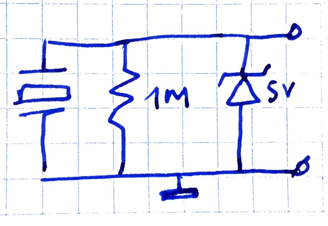
The diode is a BZT52C5V1S W8 5.1V 1/5W 0.2W SOD-323 SMD Zener Diode. The resistor loads the transducer, the diode clamps the analog signal.
This circuit tames the piezo signal somewhat, but there's a little negative component after this, and it's peaking above 5V. I'm using an Arduino MKR, and its analogue inputs don't like any of this.
image: intermediate state circuit with a normal diode and an OpAmp as buffer
I added a fast diode to deal with the negative component. In a future post I'll make an input protect PCB, based on michaelkellett's front end design. When you're using the piezo with the simple input protection, take care to only use it for vibration scenarios. I'd not use it for devices that can mechanically "shock".

Software
There are three modules in the firmware, and a cloud component.
Firmware:
- sample piezo signal fast
- get acceleration (RMS calculation over the dataset)
- cloud exchange of acceleration when its value changes
Cloud:
- register the Arduino MKR on arduino.iot
- turn it into a Thing
- register the acceleration variable
- create a dashboard
Fast ADC with DMA
I'm using ADC with DMA. My code is based on these 2 examples: 1 and 2. The ADC of the SAMD21 is set to free run, and the DMA engine copies the ADC results into my buffer.
Set up and kick off ADC - called from within setup().
void setupADC() {
  ADC->INPUTCTRL.bit.MUXPOS = 0x0;  // Set the analog input to A0
  while (ADC->STATUS.bit.SYNCBUSY)
    ;                                           // Wait for synchronization
  ADC->SAMPCTRL.bit.SAMPLEN = 0x00;             // Set max Sampling Time Length to half divided ADC clock pulse (2.66us)
  ADC->CTRLB.reg = ADC_CTRLB_PRESCALER_DIV256 |  // Divide Clock ADC GCLK by 256 (48MHz/256 = 187.5kHz)
                   ADC_CTRLB_RESSEL_12BIT |     // Set the ADC resolution to 12 bits
                   ADC_CTRLB_FREERUN;           // Set the ADC to free run
  while (ADC->STATUS.bit.SYNCBUSY)
    ;                         // Wait for synchronization
  ADC->CTRLA.bit.ENABLE = 1;  // Enable the ADC
  while (ADC->STATUS.bit.SYNCBUSY)
    ;                         // Wait for synchronization
  ADC->SWTRIG.bit.START = 1;  // Initiate a software trigger to start an ADC conversion
  while (ADC->STATUS.bit.SYNCBUSY)
    ;  // Wait for synchronization
}

void waitForDMA() {
  DMAC->CHID.reg = DMAC_CHID_ID(0);          // Select DMAC channel 0
  DMAC->CHCTRLA.reg |= DMAC_CHCTRLA_ENABLE;  // Enable the selected DMAC channel
  while (!DMAC->CHINTFLAG.bit.TCMPL);        // Wait for the DMAC to transfer complete(TCMPL) interrupt flag
  DMAC->CHINTFLAG.bit.TCMPL = 1;  // Clear the DMA transfer complete (TCMPL) interrupt flag
}

void calcRMS() {
  float vrms = analyse( 187.5, VREF, SAMPLE_NO, adcResult);
  acceleration = vrms; // update IOT Cloud variable
}
Set up DMA - called from within setup().
void setupDMA() {
  DMAC->BASEADDR.reg = (uint32_t)descriptor_section;            // Specify the location of the descriptors
  DMAC->WRBADDR.reg = (uint32_t)wrb;                            // Specify the location of the write back descriptors
  DMAC->CTRL.reg = DMAC_CTRL_DMAENABLE | DMAC_CTRL_LVLEN(0xf);  // Enable the DMAC peripheral

  DMAC->CHID.reg = DMAC_CHID_ID(0);  // Select DMAC channel 0
  DMAC->CHCTRLB.reg = DMAC_CHCTRLB_LVL(0) | DMAC_CHCTRLB_TRIGSRC(ADC_DMAC_ID_RESRDY) | DMAC_CHCTRLB_TRIGACT_BEAT;
  descriptor.descaddr = (uint32_t)0;                                            // Set up descriptor
  descriptor.srcaddr = (uint32_t)&ADC->RESULT.reg;                              // Take the result from the ADC RESULT register
  descriptor.dstaddr = (uint32_t)&adcResult[0] + sizeof(uint16_t) * SAMPLE_NO;  // Place it in the adcResult array
  descriptor.btcnt = SAMPLE_NO;                                                 // Beat count is SAMPLE_NO
  descriptor.btctrl = DMAC_BTCTRL_BEATSIZE_HWORD |                              // Beat size is HWORD (16-bits)
                      DMAC_BTCTRL_DSTINC |                                      // Increment the destination address
                      DMAC_BTCTRL_VALID;                                        // Descriptor is valid
  memcpy(&descriptor_section[0], &descriptor, sizeof(descriptor));              // Copy the descriptor to the descriptor section
}
Get a set of samples via DMA - this is called from within loop().
void waitForDMA() {
  DMAC->CHID.reg = DMAC_CHID_ID(0);          // Select DMAC channel 0
  DMAC->CHCTRLA.reg |= DMAC_CHCTRLA_ENABLE;  // Enable the selected DMAC channel
  while (!DMAC->CHINTFLAG.bit.TCMPL);        // Wait for the DMAC to transfer complete(TCMPL) interrupt flag
  DMAC->CHINTFLAG.bit.TCMPL = 1;  // Clear the DMA transfer complete (TCMPL) interrupt flag
}
Sample settings:
#define SAMPLE_NO 512  // Define the number of ADC samples

// ...

  ADC->SAMPCTRL.bit.SAMPLEN = 0x00;             // Set max Sampling Time Length to half divided ADC clock pulse (2.66us)
  ADC->CTRLB.reg = ADC_CTRLB_PRESCALER_DIV256 |  // Divide Clock ADC GCLK by 256 (48MHz/256 = 187.5kHz)
                   ADC_CTRLB_RESSEL_12BIT |     // Set the ADC resolution to 12 bits
                   ADC_CTRLB_FREERUN;           // Set the ADC to free run
RMS calculation
I've used a simplified and modified ADCDRP library.
- Modified: the library is for 8-bit ADC. The SAMD21 of the MKR WiFi 1010 is 12 bits
- Simplified: because I had to change it to 12 bits anyway, I removed all but the RMS calculation.
Here's the simplified VRMS calculation:
- Square each sample
- Sum the squared samples
- Divide the sum of the squared samples by the number of samples
- Take the square root of step 3., the mean of the squared samples
This is the ROOT-MEAN-SQUARED value.
#define SAMPLE_NO 512  // Define the number of ADC samples

uint16_t adcResult[SAMPLE_NO] = {};  // Store ADC values

#define VREF (3.3)

float analyse(float mfreq, float refv, int Abufsize, uint16_t* Adata) {
  // https://github.com/drp0/ADCDRP/blob/master/ADCDRP.cpp

/* https://forum.allaboutcircuits.com/threads/calculate-rms-value-from-sample-value.12871/
Square each sample
Sum the squared samples
Divide the sum of the squared samples by the number of samples
Take the square root of step 3., the mean of the squared samples
This is the ROOT-MEAN-SQUARED value.
*/

#define MAXVAL 0b111111111111
  int i;
  // float convert = refv / 255;
  float convert = refv / MAXVAL;
  float bufsize = float(Abufsize);

  // float midestimate = float(Amax + Amin)/2;
  float midestimate = MAXVAL/2;
  float Avrms = 0;
  float item;
  for (i = 0; i < Abufsize; i ++) {
    item = float(Adata[i]);
    Avrms +=  (item-midestimate) * (item-midestimate);
  }
  Avrms = sqrt(Avrms / bufsize);

  // convert value to voltages
  Avrms = Avrms * convert;

  return Avrms;
}
Make WiFi and DMA work together in a nice way
I have to be careful that the WiFi library's update() is called often enough, and get samples with frequency and rate that I choose. I used someone else's code to call the sample function in the loop() every 2 seconds, while keeping the loop fast. Another option would have been to not wait for the sample completion, and do the WiFI update while the DMA engine is managing the sampling and data collection.
// https://www.electronics-lab.com/project/getting-started-arduino-iot-cloud/
unsigned long lastConnectionTime = 0;              // last time you connected to the server, in milliseconds
const unsigned long postingInterval = 2000;       // delay between updates, in milliseconds

// ...

void setup() {

  // Initialize serial and wait for port to open:
  Serial.begin(9600);
  // This delay gives the chance to wait for a Serial Monitor without blocking if none is found
  delay(1500);

  WiFiDrv::pinMode(LED_GREEN, OUTPUT); //define green pin
//  WiFiDrv::pinMode(26, OUTPUT); //define red pin
//  WiFiDrv::pinMode(27, OUTPUT); //define blue pin


  // Defined in thingProperties.h
  initProperties();

  // Connect to Arduino IoT Cloud
  ArduinoCloud.begin(ArduinoIoTPreferredConnection);

  /*
     The following function allows you to obtain more information
     related to the state of network and IoT Cloud connection and errors
     the higher number the more granular information you’ll get.
     The default is 0 (only errors).
     Maximum is 4
 */
  setDebugMessageLevel(4);
  ArduinoCloud.printDebugInfo();
}

// ...

void loop() {
 ArduinoCloud.update();
  static int brightness = 15;
  static bool bFirstConnection = true;

  if (ArduinoCloud.connected() != 0) {

    // set up ADC + DMA after connection is established.
    if (bFirstConnection) {
      bFirstConnection = false;
      ArduinoCloud.printDebugInfo();
      setupDMA();
      setupADC();
    }


    // if 2 seconds have passed since your last connection,
    // then connect again and send data:
    if (millis() - lastConnectionTime > postingInterval) {
      waitForDMA();
      calcRMS();

      brightness = 15;
      WiFiDrv::analogWrite(LED_GREEN, brightness);

      lastConnectionTime = millis();
    }
    if ((brightness == 15) and (millis() - lastConnectionTime > postingInterval / 2)) {
      brightness = 0;
      WiFiDrv::analogWrite(LED_GREEN, brightness);
    }
  }
}
Arduino IOT Cloud Integration
I've used Arduino's own instructions to register the MKR WiFi 1010 to arduino.iot. You register your Arduino MKR WiFi 1010. Then you turn it into a Thing. The thing knows how to transfer your telemetry data to Arduino Cloud. In my tale, that data is the acceleration analysis of the theme park's Ferris wheel. On the cloud you can process that data, or display it on a dashboard.

Device and Thing
The first activity is to register your Arduino MKR on arduino.cc.
Then create a Thing for that device. The Thing is what we will interact with from the Arduino firmware.
Variable
On the Thing page, create a variable to hold the acceleration metric that we defined earlier.
Sketch
Once you completed this, arduino.cc will generate a sketch skeleton. You can edit, compile and debug that completely from the cloud. Or you can download it as an archive and import into the Arduino IDE for further development. The effect is the same. I took the second option. You can see the result in the software section above. Here's how an execution log looks like:
Dashboard
You can then put the Thing and Variable on an arduino.cc dashboard. You can monitor actual acceleration value and trend. A free cloud subscription allows data retention (and trends) over 15 days.
image source: cloud showing actual result of sensor input. Dips when I disturbed free vibration of my test setup
This project allows the theme park to monitor their attractions. All components and software are easily available to all. For advanced use, a better input protection circuit is needed, and it would be good to calibrate the acceleration. But it's a real-working design for capturing changes in motor / gearbox behaviour (and thus wear or damage). One of the most valued inputs for data-based predictive maintenance.
Additional Syberia art from this walktrough, from PlayStation store.
