


Hello Everyone,
Finally, I am making progress. I figured out the problem I was having with accessing the UARTs. I needed to make changes to the /boot/uEnv.txt file. The details are in Section I. After I resolved the UART problem I made the final changes to the code for the PIR sensor. I then tested different scenarios for the PIR Sensor to ensure the code was working. You can find the design for the PIR Sensor in Section II and the code in Section III.
The details for adding the PIR sensor to the Home Security System are given in the sections below:
Section I – Changes to /boot/uEnv.txt
Section II – PIR Sensor Design
Section III – PIR Sensor Code
Section IV – Security
Next, I will work on the code for controlling the lights and appliances.
Talk to you soon.
Quote of the Moment -
If at first you don’t succeed, keep on sucking until you do suck seed.
-- Curly Howard – The Three Stooges
Previous Bluetooth Challenge Home Security System Posts |
Section I - Changes to /boot/uEnv.txt
The uEnv.txt file is used to make configuration changes at boot time (Figure 1). I added Lines 3 and 4. I uncommented lines 18-21. I also modified Lines 58 and 66.
The purpose of Line 3 is to disable the HDMI pins that conflict with the pins used by the serial ports.
Line 4 enables the UART ports.
Lines 18-21 are cape overrides.
On Line 58, I added cape_universal=enable to the end of the line.
I also commented out Line 66 and added Line 67.
#Docs: http://elinux.org/Beagleboard:U-boot_partitioning_layout_2.0

cape_disable=bone_capemgr.disable_partno=BB-BONELT-HDMI,BB-BONELT-HDMIN
cape_enable=bone_capemgr.enable_partno=BB-UART1,BB-UART2,BB-UART4.BB-UART5

uname_r=4.4.91-ti-r133
#uuid=
#dtb=


###U-Boot Overlays###
###Documentation: http://elinux.org/Beagleboard:BeagleBoneBlack_Debian#U-Boot_Overlays
###Master Enable
enable_uboot_overlays=1
###
###Overide capes with eeprom

uboot_overlay_addr0=/lib/firmware/<file0>.dtbo
uboot_overlay_addr1=/lib/firmware/<file1>.dtbo
uboot_overlay_addr2=/lib/firmware/<file2>.dtbo
uboot_overlay_addr3=/lib/firmware/<file3>.dtbo
###
###Additional custom capes
#uboot_overlay_addr4=/lib/firmware/<file4>.dtbo
#uboot_overlay_addr5=/lib/firmware/<file5>.dtbo
#uboot_overlay_addr6=/lib/firmware/<file6>.dtbo
#uboot_overlay_addr7=/lib/firmware/<file7>.dtbo
###
###Custom Cape
#dtb_overlay=/lib/firmware/<file8>.dtbo
###
###Disable auto loading of virtual capes (emmc/video/wireless/adc)
#disable_uboot_overlay_emmc=1
#disable_uboot_overlay_video=1
#disable_uboot_overlay_audio=1
#disable_uboot_overlay_wireless=1
#disable_uboot_overlay_adc=1
###
###PRUSS OPTIONS
###pru_rproc (4.4.x-ti kernel)
uboot_overlay_pru=/lib/firmware/AM335X-PRU-RPROC-4-4-TI-00A0.dtbo
###pru_uio (4.4.x-ti & mainline/bone kernel)
#uboot_overlay_pru=/lib/firmware/AM335X-PRU-UIO-00A0.dtbo
###
###Cape Universal Enable
enable_uboot_cape_universal=1
###
###Debug: disable uboot autoload of Cape
#disable_uboot_overlay_addr0=1
#disable_uboot_overlay_addr1=1
#disable_uboot_overlay_addr2=1
#disable_uboot_overlay_addr3=1
###
###U-Boot fdt tweaks...
#uboot_fdt_buffer=0x60000
###U-Boot Overlays###

cmdline=coherent_pool=1M net.ifnames=0 quiet cape_universal=enable
#cmdline=coherent_pool=1M net.ifnames=0 quiet cape_universal=enable

#In the event of edid real failures, uncomment this next line:
#cmdline=coherent_pool=1M net.ifnames=0 quiet video=HDMI-A-1:1024x768@60e

##Example v3.8.x
#cape_disable=capemgr.disable_partno=
#cape_enable=capemgr.enable_partno=bone_capemgr.enable_partno=cape-universala
cape_enable=bone_capemgr.enable_partno=cape-universala

##Example v4.1.x
#cape_disable=bone_capemgr.disable_partno=
#cape_enable=bone_capemgr.enable_partno=

##enable Generic eMMC Flasher:
##make sure, these tools are installed: dosfstools rsync
#cmdline=init=/opt/scripts/tools/eMMC/init-eMMC-flasher-v3.sh
Figure 1. /boot/uEnv.txt
Section II - PIR Sensor Design
There are three main modules in the PIR Sensor design; the HSS Controller, the HSS Web Server, and the Human Sensor Server (Figure 2).
The Human Sensor Server monitors the PIR Sensor (Figure 4). If the PIR Sensor is triggered, the Human Sensor Server sends a message to the HSS Controller indicating that someone triggered the PIR Senor. The HSS Controller calls the Process Request module which instructs text-to-speech hardware (Figure 3) to speak a "Intruder Detected" message. The Process Request module then sets the P8_20 pin on the BeagleBone Black high. When the HSS Web Server detects that the pin is HIGH it sends a message to the browser informing it to set the PIR Sensor button to red. If the home owner presses the red PIR Sensor button, the browser sets the button to green and sends a message to the HSS Web Server. The HSS Web Server sets the P8_20 pin low. When the HSS Controller detects that the P8_20 pin is low it sends a message to the Process Request module which sends an "All Clear" message to the text-to-speech hardware.

Figure 2.
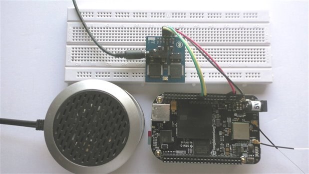
Figure 3. Emic2 Text-to-Speech module with an external speaker, attached to a BeagleBone Black Wireless

Figure 4. HC-05 & PIR Sensor attached to a Adafruit Trinket Pro
Section III - PIR Sensor Code
human-sensor-server.ino
human-sensor-server.ino is an Arduino sketch (Figure 5). This sketch monitors the PIR Sensor. When the PIR Sensor is triggered it sends an alert to the HSS Controller.
It uses the softwareSerial module instead of the hardware serial port for communicating with the Bluetooth module. SoftwareSerial uses pin 3 as the receive port and pin 4 for the transmit port. (Lines 1 & 2).
Lines 3-8 defines the variables used.
Line 11 initializes the Bluetooth serial port.
Line 12 initializes the Arduino's serial port. If necessary it can be used as a debug port.
The Arduino pin that is attached to the PIR Sensor is set to input, on Line 13.
Line 14 initializes the data buffer.
Lines 16-21 waits for a message from the HSS Controller before continuing to the Loop function.
First, the Loop function (Lines 25-40) checks for messages sent from the HSS Controller. Currently, no message is sent by the HSS Controller. Next, it checks to see if an alert was sent. If an alert was sent it will call DelaySensorCheck, which waits for 5 minutes before returning control back to the Loop function. It then sets the alertSent flag to "false". If no alert was sent ( alertSent flag equals "false") the Loop function calls the CheckSensor function, then calls the SendHeartbeat Function.
The ClearBuffer function (Lines 42-48) sets the data buffer to nulls.
The CheckForMessage function (Lines 50-59) checks for a message from the HSS Controller. If one is detected, it calls the ProcessRequest function. Currently, the HSS Controller is not sending any messages to the PIR Sensor module.
The CheckSensor function (Lines 61-70) checks the PIR Sensor pin and if it is high it sets the alertSent flag to "true" and calls the SendAlert function.
The DelaySensorCheck function (Lines 72-79) waits for 5 minutes before allowing the Loop to check for PIR Sensor.
The ProcessRequest function (Lines 81-97) processes any requests that come from the HSS Controller. Currently this function is not used.
The SendAlert function (Lines 99-104) sends an alert message to the HSS Controller. This message contains a Status of "1" which tells the HSS Controller that the SIR Sensor was triggered.
The SendHeartbeat function (Lines 106-112) sends a status of "H" to the HSS Controller. This lets the HSS Controller know that the PIR Sensor is still online.
#include <SoftwareSerial.h>
SoftwareSerial BTserial(3, 4);
char dataBuffer[81];
String stringBuffer;
int pirPin = 6;
int pirPinVal = LOW;

boolean alertSent = false;

void setup(){
  BTserial.begin(9600);
  Serial.begin(9600);
  pinMode(pirPin, INPUT);
  ClearBuffer();

  while (!BTserial.available())
  {
    // Wait for a connected message from the HHS Controller
  } // if(!BTserial.available())
      BTserial.readBytes(dataBuffer,80);
      delay(10000);

} // End setup()

void loop(){

  CheckForMessage();
  if(alertSent)
    {
      DelaySensorCheck();
      alertSent = false;
    }
    else
    {
      CheckSensor();
      SendHeartbeat();
      delay(10000);
    }

} // End loop()

void ClearBuffer()
{
  for (int i = 0; i < 80; i++)
  {
    dataBuffer[i] = 0;
  } // End for (int i = 0; i < 80; i++)
} // End ClearBuffer()

void CheckForMessage()
{
  if( BTserial.available())
  {
    BTserial.readBytes(dataBuffer,80);
    stringBuffer = dataBuffer;
    ProcessRequest();
    ClearBuffer();
  } // End if( BTserial.available())
} // End CheckForMessage()

void CheckSensor()
{
    pirPinVal = digitalRead(pirPin);

    if (pirPinVal == HIGH)
    {
       SendAlert();
       alertSent = true;
    } // End if (pirPinVal == HIGH)
} // End CheckSensor()

void DelaySensorCheck()
{
  for (int i=1;i<6;i++)
  {
   delay(300000);
   SendHeartbeat();
  } // End for (int i=1;i<6;i++)
} // End DelaySensorCheck()

void ProcessRequest()
{
  // Source_Adapter_Id Destination_ Adapter_Id Max_Transmission_Count Status Data
  // 000               001                     02                     0/1

  if(stringBuffer.substring(0,3) == "000" && stringBuffer.substring(3,6) == "001")
  {
    if(stringBuffer.substring(8,9) == "0")
    {
      alertSent = false;
    }
    else
    {
      alertSent = true;
    } // End if(stringBuffer.substring(8,9) == "0")
  } // End if(stringBuffer.substring(0,3) == "000" && stringBuffer.substring(3,6) == "001")
} // End ProcessRequest()

void SendAlert()
{
  // Source_Adapter_Id Destination_ Adapter_Id Max_Transmission_Count Status Data
  // 001               000                     02                     1
  BTserial.print("001000021$");
}

void SendHeartbeat()
{
  //ClearBuffer();
  // Source_Adapter_Id Destination_ Adapter_Id Max_Transmission_Count Status Data
  // 001               000                     02                     H
  BTserial.print("00100002H$");
} // End SendAllClear()
Figure 5.
hss-controller.py
hss-controller.py is a python program that controls data passed from the Bluetooth modules (Figure 6). It accepts messages from the Bluetooth modules. It sends messages to the text-to-speech module. It checks the status of GPIO pins and calls the ProcessRequest.py when necessary.
Lines 3-8 import the required modules.
Line 10 sets the PIR Sensor GPIO pin to as an output pin.
Line 12 initializes the pirSensorStatus to zero.
Lines 13-14 initializes the bluetoothAddress array. Currently, it only contains the address for the HC-05 used by the PIR Sensor.
Lines 16-17 connects to the Bluetooth module for the PIR Sensor.
Line 20 creates a never ending loop.
Line 21 calls the bluetoothSockets program, which checks for data on the Bluetooth socket. The ReceiveData function blocks, therefore the function will not return until it receives data on the Bluetooth socket. The purpose of the heartbeat from the PIR Sensor module is to send data to the ReceiveData function so it can return back to the hss-controller.py program.
Lines 22-25 parses the data received from a Bluetooth module.
Lines 26-36 processes the data received from a Bluetooth module. If the status is a "0" or "1" it checks to see if the destination_Adapter_Id is "000" (BleageBone Black). If the destination_Adapter_Id is not "000" the data is ignored. It then checks to see if the source_Adapter_Id is "001" (PIR Sensor). If it is it calls the PirSensor function in the processRequest module and sets the pirSensorStatus variable to "1". Currently the PIR Sensor will only send a status of "1". Therefore, the PirSensor function will generate an "alert" message. Next, it checks the PIR Sensor pin (P8_20). If the pin is high it does nothing, otherwise it checks if the pirSensorStatus variable is equal to "1". If it is it calls the PirSensor function in the processRequest module and sets the pirSensorStatus variable to "0". Since the PirSensor function is passed a "0" it will generate an "all clear" message.
# hss-controller.py

import Adafruit_BBIO.GPIO as GPIO
import serial
import bluetooth
import time
import bluetoothSockets
import processRequest

GPIO.setup("P8_20", GPIO.OUT)

pirSensorStatus = "0";
bluetoothAddress = ["00:14:03:06:58:68", # PIR Sensor
                    "00:00:00:00:00:00"]

socket = bluetoothSockets.CreateSocket()
bluetoothSockets.ConnectSocket(socket, bluetoothAddress[0])


while (1 == 1):
  bluetoothData = bluetoothSockets.ReceiveData(socket)
  source_Adapter_Id = bluetoothData[0:3]
  destination_Adapter_Id = bluetoothData[3:6]
  max_Transmission_Count = bluetoothData[6:8]
  status = bluetoothData[8:9]
  if (status != "H"):
     if (destination_Adapter_Id == "000"):
        if (source_Adapter_Id == "001"):
           processRequest.PirSensor(status)
           pirSensorStatus = "1"
  if GPIO.input("P8_20"):
     // print "Do Nothing"
  else:
     if (pirSensorStatus == "1"):
        processRequest.PirSensor("0")
        pirSensorStatus = "0"


sock.close()
Figure 6.
bluetoothSockets.py
bluetoothSockets.py is a python program that handles the socket connections for communicating with the Bluetooth devices (Figure 7).
Lines 1-2 contain the import statements for the bluetoothSockets module.
Line 4 contains the global socket variable that is used by the functions in this module.
Lines 6-8 (CreateSocket function) creates a socket object used by the rest of the functions.
Lines 10-14 (ConnectSocket function) connect to the Bluetooth device specified by serverAddr. In this case it is the PIR Sensor's Bluetooth device. The connection will use port 1. Line 12 makes the connection. Line 13 sends a message to the Bluetooth device letting it know it is now connected to the BeagleBone Black.
Lines 16-25 (ReceiveData function) retrieve data from the Bluetooth device. Lines 17-18 initializes the buffers. Line 20 waits five seconds to ensure any incoming data is received. Lines 21-23 reads the incoming data and stores it in bluetoothData until a Dollar Sign ("$") is received. Note that the socket.recv command is blocking (It waits until it receives data before releasing control to the next command). Therefore, this function will not return control back to the calling function until it receives data.
import bluetooth
import time

global sock

def CreateSocket():
  sock=bluetooth.BluetoothSocket( bluetooth.RFCOMM )
  return sock

def ConnectSocket(sock, serverAddr):
  port = 1
  sock.connect((serverAddr, port))
  sendcount=sock.send("Hello Bluetooth Device!!!")


def ReceiveData(socket):
  receiveBuffer = ""
  bluetoothData = ""

  time.sleep(5)
  while ("$" not in receiveBuffer):
     receiveBuffer = socket.recv(80)
     bluetoothData = bluetoothData + receiveBuffer

  return bluetoothData
Figure 7.
processRequest.py
The processRequest.py is a python program (Figure 8) that performs tasks depending on what status is passed to it. The status is either an one for on or a zero for off.
Lines 1-2 contain the import statements.
Lines 04-13 contain the commands for the PirSensor function. If a status of one is sent to the PirSensor function, a call to the alert module will be made 3 times. A message will be passed to the speak function to be output to the speaker attached to the speech-to-text module. Also, the P8_20 pin is set high to communicate to other modules that a warning alert has been issued by the PIR Sensor. If the status is zero, an all clear message is sent to the speak function and the P8_20 pin is set low to communicate to other modules that a warning alert has been issued by the home owner (via the webpage).
import alert
import Adafruit_BBIO.GPIO as GPIO

def PirSensor(status):

  if (status == "1"):
     alert.speak("S Warning! Warning! a intruder has been detected!")
     alert.speak("S Warning! Warning! a intruder has been detected!")
     alert.speak("S Warning! Warning! a intruder has been detected!")
     GPIO.output("P8_20", GPIO.HIGH)
  else:
     alert.speak("S The intruder alert has been cleared!")
     GPIO.output("P8_20", GPIO.LOW)
Figure 8.
alert.py
alert.py is a python program (Figure 9) that accepts messages to send to the text-to-speech module.
Lines 1-5 imports the required modules.
Lines 8-14 (setup function) sets up communications with the speech-to-text module. It defines UART1 as the serial port to use for the communications (Line 9). Line 11 initializes the global variable serial1. Line 12 creates the serial object (serial1). It then closes and reopens the serial port (Lines 13-14).
Lines 16-34 reads data sent from the speech-to-text module. Lines 18-19 defines the variable data as global. Line 20 reads the first byte from the speech-to-text module. Lines 21-31 reads the remaining bytes. Note that on Line 21 the While loop checks for a colon (":"). The speech-to-text module sends a colon when it has completed its transmission of data and is ready to receive commands. Each byte received is added to the data variable (Line 26). Lines 28-29 add a line feed whenever a carriage return is encountered. Lines 30 adds a delay to give a little time for the next byte to arrive. Line 31 reads another byte. Line 32 stores the data received from the speech-to-text module into the data variable. Line 33 flushes the serial input buffer. Lines 34 returns the data to the calling function.
Lines 34-38 (waitForHal function - Hal from the movie 2001 A space odyssey) waits the specified period before reading the incoming data from the serial port. The purpose of the delay is to give the speech-to-text module time to process the previous request. If the speech-to-text module is outputting a message and another message is sent to it, it will interrupt the current message and start outputting the new message.
Lines 40-42 (delay function) converts the input from milliseconds to seconds, then executes the delay.
Lines 44-52 (speak function) sends the message to the speech-to-text module to output to the speaker. Line 45 initializes the serial port. Line 46 tells the speech-to-text module to set the volume on high. Line 47 specifies which voice the speech-to-text module should use. Line 51 sends the speech-to-text module the message to output to the speaker. Line 52 calculates the delay to use depending on the length of the message.
import Adafruit_BBIO.GPIO as GPIO
import Adafruit_BBIO.UART as UART
import serial
import subprocess
import time


def setup():
  UART.setup("UART1")

  global serial1
  serial1.Serial(port = "/dev/ttyO1", baudrate=9600)
  serial1.close()
  serial1.open()

def serial_rx():
  """ Returns received data if any, otherwise current data buffer. """
  global data
  data = ""
  emicData = serial1.read()
  while(emicData != ":"):

      # If multiple characters are being sent we want to catch
      # them all, so add received byte to our data string and
      # delay a little to give the next byte time to arrive:
      data += emicData
      number = ord(emicData)
      if (number == 13):
         data += (chr(10))
      time.sleep(0.1)
      emicData = serial1.read()
  data += emicData
  serial1.flush()
  return data

def waitForHal(delayLength):
    delay(delayLength)
    serialData = serial_rx()

def delay(delayLength):
    sleepTime = delayLength / 1000;
    time.sleep(sleepTime)

def speak(message):
   setup()
   serial1.write("V4\n")
   waitForHal(5000)
   serial1.write("N4\n")
   waitForHal(1000)

   serial1.write(message + "\n")
   delayLength = ((len(message) / 10 + 1) * 1000) + 2000
Figure 9.
hss.py
hss.js is a JavaScript program (Figure 10). This is the web server code that communicates with the web browser and the BeagleBone Black.
Lines 2-5 import the required modules.
Line 7 specifies where the HTML page is stored.
Line 9 initializes the pinStates array.
Line 10 initializes the socket variable.
Line 12 specifies which port to run the web server on. The BeagleBone runs its web server on port 80, so I choose port 9090.
Lines 14-25 (handler function) serves up the web page.
Lines 27-31 (onConnect function) creates the socket connection. Lines 28-29 sets up web browser requests. Line 28 specifies that the handleDigitalWrite function should be called if the web browser sends a digitalWrite request. Line 29 specifies that the handleMonitorRequest function should be called if the web browser sends a monitor requests.
Lines 33-36 (handleMonitorRequest function) is called whenever a monitor request is received from the web browser. Line 34 sets the pin mode to input, in this case for pin P8_20. Line 35 adds the pin (in this case P8_20) to the pinStates array and set the pin state to zero.
Lines 38-44 (handleDigitalWrite function) changes the state of the specified BeagleBone Black pin. The home owner will press the appropriate button on the web page which then issues a request to change the pin state. Line 39 takes the message passed to the handleDigitalWrite function and parses it. The data object contains two fields: data.pin, which contains the BeagleBone Black pin number (In this case P8_20); and data.value, which contains a "0" for a low pin state or a "1" for a high pin state. In Line 42, the pin mode is set to output. In line 43, the pin is set to the appropriate value.
Lines 46-55 (checkInputs function) check to see is the status of a BeagleBone Black pin has changed. If the pin status has changed the function will report the change to the web browser. Lines 47-54 step each pin in the pinStates array checking to see if any of the pin states changed. Line 48 stores the state of the pin in the pinStates array in the oldValue variable. Line 49 stores the current state of the pin in the newValue variable. If the state of a pin in the pinStates array (oldValue) does not match the current state (newValue) of the pin (Line 50) then the new state of the pin is passed to the web browser (Line 51). The new value is then stored in the pinStates array (Line 52).
Line 57 guarantees that the onConnect function is executed.
Line 59 executes the checkInputs function every 500 milliseconds.
// hhs.js
var app = require('http').createServer(handler);
var io  = require('/usr/local/lib/node_modules/bonescript/node_modules/socket.io').listen(app);
var fs  = require('fs');
var bb  = require('bonescript');

var htmlPage = '/home/debian/HSS/hss.html';

var pinStates = {};
var soc;

app.listen(9090);

function handler (req, res) {
  fs.readFile(htmlPage,
    function (err, data) {
      if (err) {
        res.writeHead(500);
        return res.end('Error loading file: ' + htmlPage);
      }
      res.writeHead(200);

      res.end(data);
    });
}

function onConnect(socket) {
    socket.on('digitalWrite', handleDigitalWrite);
    socket.on('monitor', handleMonitorRequest);
    soc = socket;
}

function handleMonitorRequest(pin) {
    bb.pinMode(pin, bb.INPUT);
    pinStates[pin] = 0;
}

function handleDigitalWrite(message) {
    var data = JSON.parse(message);


    bb.pinMode(data.pin, bb.OUTPUT);
    bb.digitalWrite(data.pin, data.value);
}

function checkInputs() {
    for (var pin in pinStates) {
        var oldValue = pinStates[pin];
        var newValue = bb.digitalRead(pin);
        if (oldValue != newValue) {
            soc.emit("pinUpdate", '{"pin":"' + pin + '", "value":' + newValue + '}');
            pinStates[pin] = newValue;
        }
    }
}

io.sockets.on('connection', onConnect);

setInterval(checkInputs, 500);
Figure 10.
hss.html
hss.html contains the HTML and JavaScript code to display and modify the web browser. The hss.html code is explained in Section I of Post 5. I will describe the changes made to hss.html to implement the PIR Sensor functionality (Figure 11).
The script on Line 116 is used by the logic that processes changes to the BeagleBone Black pins, such as the P8_20 pin used by the PIR Sensor.
The code on Line 122 specifies that when the web browser receives a pinUpdate request it should call the handlePinUpdate function.
Line 124 tells the web server to montior the P8_20 pin.
Lines 245 and 249 have been changed to reflect the PIR Sensor pin - P8_20.
The handlePinUpdate function was added (Lines 255-275). When the handlePinUpdate function is called the code on Line 257 parses the message into the data object. If data.value is "0" the motion sensor button is set to green (Line 263). If data.value is "1" the motion sensor button is set to red (Line 271).
<html>
<head>

<style>


/* The switch - the box around the slider */
.switch {
  position: relative;
  display: inline-block;
  width: 60px;
  height: 34px;
}

.switch input {display:none;}


.slider {
  position: absolute;
  cursor: pointer;
  top: 0;
  left: 0;
  right: 0;
  bottom: 0;
  background-color: green;

  -webkit-transition: .4s;

  transition: .4s;

}


.slider:before {
  position: absolute;
  content: "";
  height: 26px;
  width: 26px;
  left: 4px;
  bottom: 4px;
  background-color: white;
  -webkit-transition: .4s;
  transition: .4s;
}

input:checked + .slider {

  background-color: red;

}


input:focus + .slider {
  box-shadow: 0 0 1px #2196F3;

}


input:checked + .slider:before {
  -webkit-transform: translateX(26px);
  -ms-transform: translateX(26px);
  transform: translateX(26px);
}

/* Rounded sliders */

.slider.round {

  border-radius: 34px;

}


.slider.round:before {
  border-radius: 50%;
}

.grid-container {

  display: grid;

  grid-template-columns: auto auto;

  background-color: #2196F3;

  padding: 10px;


}
.grid-item {
  background-color: rgba(255, 255, 255, 0.8);
  border: 1px solid rgba(0, 0, 0, 0.8);
  padding: 20px;
  font-size: 30px;
  text-align: left;
  color: black
}

.hss-heading-font {

    font-family: "Arial", cursive, bold, sans-serif;

    font-size: 48px;

    color: blue;

}


</style>

<script src = "/socket.io/socket.io.js"> </script>


<script type=text/javascript src="http://code.jquery.com/jquery-3.3.1.min.js"></script>

<script>

  var socket = io.connect();

  socket.on("pinUpdate", handlePinUpdate);

  socket.emit('monitor', 'P8_20');

  function FunLivingRoomLight(){

     var x = document.getElementById("LivingRoomLight").checked;

     if(x == false)

     {

       socket.emit('digitalWrite', '{"pin":"USR3", "value":0}');

     }

     else

     {

       socket.emit('digitalWrite', '{"pin":"USR3", "value":1}');

     }

  }


  function FunTV(){
     var x = document.getElementById("TV").checked;
     if(x == false)
     {
       socket.emit('digitalWrite', '{"pin":"USR3", "value":0}');
     }
     else
     {
       socket.emit('digitalWrite', '{"pin":"USR3", "value":1}');
     }
  }

  function FunGarageDoor(){

     var x = document.getElementById("GarageDoor").checked;

     if(x == false)

     {

       socket.emit('digitalWrite', '{"pin":"USR3", "value":0}');

     }

     else

     {

       socket.emit('digitalWrite', '{"pin":"USR3", "value":1}');

     }

  }

  function FunGasRange(){

     var x = document.getElementById("GasRange").checked;

     if(x == false)

     {

       socket.emit('digitalWrite', '{"pin":"USR3", "value":0}');

     }

     else

     {

       socket.emit('digitalWrite', '{"pin":"USR3", "value":1}');

     }

  }


  function FunCarbonMonoxideSensor(){
     var x = document.getElementById("CarbonMonoxideSensor").checked;
     if(x == false)
     {
       socket.emit('digitalWrite', '{"pin":"USR3", "value":0}');
     }
     else
     {
       socket.emit('digitalWrite', '{"pin":"USR3", "value":1}');
     }
  }

  function FunNaturalGasSensor(){

     var x = document.getElementById("NaturalGasSensor").checked;

     if(x == false)

     {

       socket.emit('digitalWrite', '{"pin":"USR3", "value":0}');

     }

     else

     {

       socket.emit('digitalWrite', '{"pin":"USR3", "value":1}');

     }

  }


  function FunMotionSensor(){
     var x = document.getElementById("MotionSensor").checked;
     if(x == false)
     {
       socket.emit('digitalWrite', '{"pin":"P8_20", "value":0}');
     }
     else
     {
       socket.emit('digitalWrite', '{"pin":"P8_20", "value":1}');
     }
  }


  function handlePinUpdate(message) {

    var data = JSON.parse(message);

    if (data.value == 0)

    {

       document.getElementById("MotionSensor").checked = false;

    }

    else

    {

       document.getElementById("MotionSensor").checked = true;

    }

  }


  function FunFrontDoorCamera(){
     var x = document.getElementById("FrontDoorCamera").checked;
     if(x == false)
     {
       socket.emit('digitalWrite', '{"pin":"USR3", "value":0}');
     }
     else
     {
       socket.emit('digitalWrite', '{"pin":"USR3", "value":1}');
     }
  }

  function FunBackYardCamera(){

     var x = document.getElementById("BackYardCamera").checked;

     if(x == false)

     {

       socket.emit('digitalWrite', '{"pin":"USR3", "value":0}');

     }

     else

     {

       socket.emit('digitalWrite', '{"pin":"USR3", "value":1}');

     }

  }

</script>


</head>

<body>


<div>Home Security System</div>
<br><br>
<div>
  <div>Living Room Light</div>
  <div>
    <label>
    <input id="LivingRoomLight" type="checkbox" onClick="FunLivingRoomLight();">
    <span "grid-item"></span>
    </label>
  </div>
  <div>TV</div>
  <div>
    <label>
    <input id="TV" type="checkbox" onClick="FunTV();">
    <span "grid-item"></span>
    </label>
  </div>
  <div>Garage Door</div>
  <div>
    <label>
    <input id="GarageDoor" type="checkbox" onClick="FunGarageDoor();">
    <span "grid-item"></span>
    </label>
  </div>
  <div>Gas Range</div>

  <div>

    <label>

    <input id="GasRange" type="checkbox" onClick="FunGasRange();">

    <span "grid-item"></span>

    </label>

  </div>

  <div>Carbon Monoxide Sensor</div>

  <div>

    <label>

    <input id="CarbonMonoxideSensor" type="checkbox" onClick="FunCarbonMonoxideSensor();">

    <span "grid-item"></span>

    </label>

  </div>

  <div>Natural Gas Sensor</div>

  <div>

    <label>

    <input id="NaturalGasSensor" type="checkbox" onClick="FunNaturalGasSensor();">

    <span "grid-item"></span>

    </label>

  </div>


  <div>Motion Sensor</div>
  <div>
    <label>
    <input id="MotionSensor" type="checkbox" onClick="FunMotionSensor();">
    <span "grid-item"></span>
    </label>
  </div>
  <div>Front Door Camera</div>
  <div>
    <label>
    <input id="FrontDoorCamera" type="checkbox" onClick="FunFrontDoorCamera();">
    <span "grid-item"></span>
    </label>
  </div>
  <div>Back Yard Camera</div>
  <div>
    <label>
    <input id="BackYardCamera" type="checkbox" onClick="FunBackYardCamera();">
    <span "grid-item"></span>
    </label>
  </div>
Figure 11.
Section IV - Security
Backups
Backups are an important part of the security of your system. We think about backing up our data at work and our PCs at home. We should also backup the files on our microcomputers, such as the BeagleBone Black. Just like your PC, if you do not have any backups on your microcomputer and a hacker accesses your computer and delete files on your computer you could lose valuable information. Also, think about the time you spent developing code for your microcomputer. Do you want to recreate that code again? Hackers are not the only problem. Your micro computer could fail due to a hardware problem or an electrical surge. So, backup your microcomputer on a regular basis.
There are a variety of software packages you can use to back up your files. Some of the packages are open source, therefore they are free. Other packages are proprietary and will cost to install them. Some software packages allow you to perform partial backups, saving you time when performing backups. Some packages allow you to clone the microSD card. The disadvantage to cloning the SD card is that you cannot recover individual files. The ability to recover individual files comes in handy when you accidentally delete a file.
However, you can also do what I do and use Filezilla to back up the files on your microcomputer. I backup all of my application files. I also document how I install any software on the microcomputer. This way I can recover individual files or the entire system.
Whichever way you choose to back up your files be sure you do it on a regular basis so you do not lose any data if a failure occurs.
Top Comments