This chapter focuses on what it’s like to use the instruments on-the-bench, without considering computer-based remote control or connectivity. This is the way that many instruments, traditionally, would have been used at undergraduate level university labs and is how many continue to use their instruments afterwards, thus is a matter of key importance. This section will evaluate key aspects of the instrument’s ergonomics, ease of use and perform some simple experiments that can (mostly) be run standalone to demonstrate key capabilities.
Evaluations of the instruments were performed with a mix of the shipped firmware and the latest firmware available at the time. Firmware versions were 02.12.2021071625 for EDUX1052G, K0103040100010401000100 for EDU33212A, K010703010001100105 for EDU34450A and K010503010001050101 for EDU36311A at the point of publication.
As there are many parts to this section, feel free to jump to the sections most interesting to you. Video-sections are marked with an asterisk (*). Owing to the need to keep the review to a reasonable length, not every single aspect of each instrument’s interface can be documented.
Table of Contents
General Impressions
At first glance, with the instruments stacked in the 2x2 configuration seen on the brochure, the arrangement is very unique and quite attractive. It looks unlike most instrument benches which often have mixtures of various screens of different types and sizes – everything just meshes together and the dark colour theme makes it look modern.
Using the instruments, the rubber keypad buttons and input jacks all feel about as sturdy as one would expect. The hardware power switch has a satisfying click and the plastic casing feels decently solid as each instrument as an internal metal chassis and a decent amount of heft to it to stop it from sliding across the bench. Even the non-touch LCD screens seem sufficiently sturdy, with a matte protective cover that resists scratching from an accidentally wayward probe or cable connector.
The “signature” 7” 800x480 pixel LCD is perhaps one of the key selling points of Keysight’s Smart Bench Essentials instruments. I feel this is perhaps a good idea as LCDs can be quite economical and the benefit of more sophisticated graphics and colour can serve to enhance the ease of use of the instrument. Larger screens can also enable the possibility of using larger fonts to ease readability. However, after powering up my units, my enthusiasm was dampened slightly.
I understand that given the economical price-point of the instrument that we can’t have everything. Having been accustomed to newer, mainstream touch-controlled instruments, the large screen often results in me accidentally trying to press the options or soft-keys with my finger. Had the LCD not been tablet-sized, I probably wouldn’t have tried …
During boot-up, while the unit is displaying a black screen, the LCD screen shows noticeably non-uniformity in the backlight. When operating, I noticed the screen seemed to have a very “average” viewing angle suggesting it maybe TN-based.

It was then that I noticed that my unit’s LCDs seem to have a dot-crawl effect which may because of poor AC-symmetry driving the LCD sub-pixel, the use of time-dithered drive to obtain higher colour depths and/or the interactions between a PWM-ed backlight. The effect is that the screen has a distracting flickering effect depending on the displayed content reminiscent of dot-crawl in analog TVs. Unfortunately, there is no facility to adjust the screen brightness on any of the instruments.
This particular effect can make certain menus a little more difficult to use because of the fine detail involved and limited resolution of the LCD. Of course, I appreciate that we’re not watching videos or doing print-proofing on these screens so perfect quality is not the priority, however, this does illustrate that perhaps some corners were cut here to meet the price-point. It is serviceable, but perhaps not as much of a pleasure to use as I had anticipated.
Of note is that at the recent ElectroneX trade show in Sydney, I visited the Keysight booth to find they had some Smart Bench Essentials instruments with a glossy LCD screen finish and seemingly better contrast as a result. This suggests to me that there may be instruments out there with different hardware.
Perhaps it is then important to consider – given the large LCD screen, what do we lose as a result? The answer is front-panel real-estate for buttons. While the front panel of these instruments is larger than most competing ordinary ½-width 2RU high instruments, the operation panel to the right of the screen does feel cramped. Especially with the EDUX1052G oscilloscope, I find myself accidentally bumping a knob and throwing off a trace offset inadvertently as I’m trying to adjust something else. Similarly, in the EDU36311A power supply, the Channel 2 output button is quite close to the All On/Off button which can result in inadvertent operations. But I will speak more of this in the discussion of each instrument.
One thing that is good is the consistent use of the soft-keys that flank the right of the screen on all instruments. The menus visually appear the same across instruments, with very similar arrangements of common options. However, this only serves to highlight the minor differences that arise when interacting with some menu items – on the oscilloscope, this usually uses a rotary knob with centre-push button to select, but on other instruments, this is either directional arrow buttons or a knob without centre-push and a separate button. This can be a minor frustration, but does not affect usability in any major way.
All instruments seem to incorporate a real-time clock which indicates there is a battery that will eventually need replacing. Unfortunately, the process of setting the clock via the front panel does not allow setting a value for the seconds, thus the instruments are never able to perfectly align their times which is a minor annoyance.
While boot times are probably not all that relevant for instruments that would probably be started up in the morning and left on throughout the day, I’m sure some people would want to know. In short, none of the instruments are particularly speedy, although the PSU wins the race with 12.43s measured by my stopwatch. The DMM comes next, pushing out its first reading by 19.38s. The AWG comes in third place with a less-impressive 27.24s, with the DSO taking the wooden spoon at 44.52s to its first trace. At least, we get a bit of a light show with chasing LEDs on most instruments as they run their boot-up sequence. Given that instruments are supposed to be warmed up to attain their accuracy, I feel that boot-up times are not all that relevant in reality.
Acoustically, the DMM being fan-less is pretty much silent. The DSO and AWG however have their own fans which often run at a slow pace, resulting in a noticeable low “motorboating” noise. Perhaps the most offensive is the PSU which has a large fan that likes to run at moderate speeds or greater. There is a noticeable airflow noise comparable to a full-size desktop computer running. Once all instruments are powered up and idling, the cumulative noise from the set is noticeable in a quiet room and could be distracting to some. It is good to see all instruments have the facility to turn off the beeper to ensure a “quiet” lab.
EDU34450A 5.5-digit Dual-Display Digital Multimeter
The first instrument I got acquainted with was the DMM, as it’s been a while since I’ve had a new DMM on the bench.
While the meter does seem to be a competent DMM, there seems to be a number of compromises to keep the price-point down. The stated DC basic accuracy of 0.015% to 0.027% is not as good as other instruments in the 5.5-digit class which are frequently in the 0.012% range. Unlike more serious DMMs, the integration time can only be set between pre-set settings of Fast, Medium and Slow rather than by NPLC. The current range is also somewhat limited, topping out at 3A without a 10A range. Finally, the temperature measurement capability is thermistor-based, rather than thermocouple-based which is more common and requires specific reference junction compensation.

One frustration I had was with the continuity beeper function which seems to be software-based, resulting in noticeable delay between probe-tips touching and a beep sounding. This limits the usability of this feature. Another is the fact that the USB front-panel host port is not very useful, only allowing to save settings. There seems to be no screenshot or data logging facility despite the hardware being there – the only data logging is to the internal 5kpts memory and the logging minimum interval is approximately 6 seconds which is very slow.
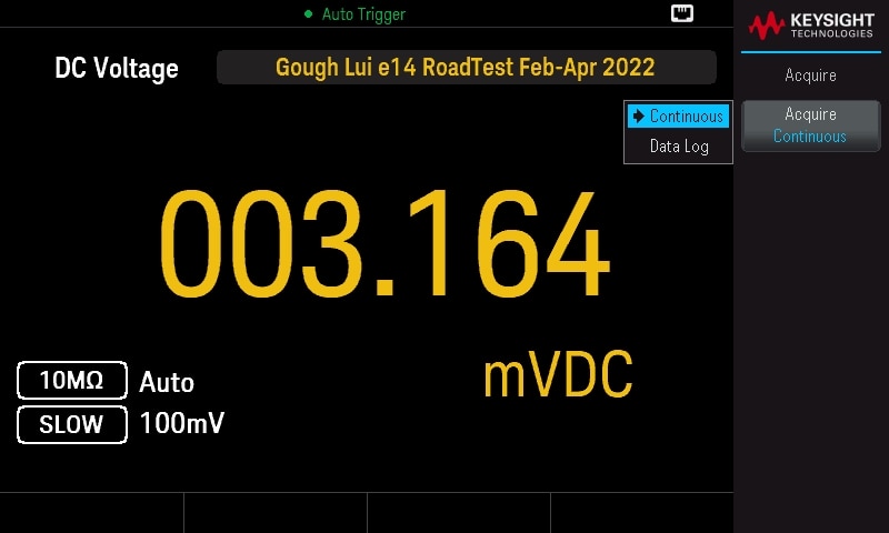
One thought I had was the 4A fuse for the 3A current range – pairing this DMM with a power supply that can put out 6A on Channel 1 is perhaps not a great idea if you want to avoid blown fuses in the lab by saboteurs!
Key User Interface Elements
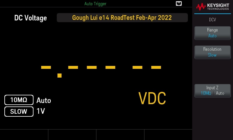
The reading generally takes the majority of the display which is a good design. There is a fixed banner text area across the top which can be used to label a bench, but ordinarily displays the model number. The measurement settings are shown in the bottom left.
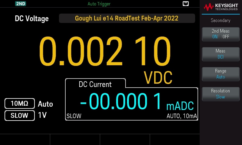
Under certain combinations of functions, it is possible to do multiple measurements sequentially and display them side-by-side in dual-display mode. Depending on the range, however, this can result in excessive relay switching which is a common caveat.
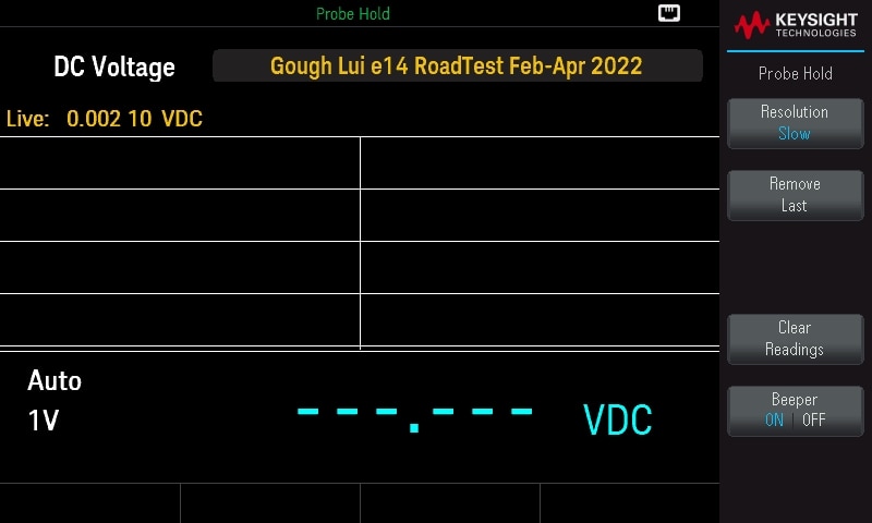
There are various functions including probe-hold, math, zero-resistance offset compensation and more. For the price, I feel the DMM is offering quite a lot of functionality even with the compromises.
Experiment: Finding a Suitable Thermistor for Temperature Measurement
According to the datasheet, the suitable thermistor probe for the temperature mode is a YSI 4407. The problem is that this doesn’t exist – I suspect they mean the YSI 44007, a 5kOhm thermistor with a 0-50°C Beta value of 3891K and a resistance ratio 25/125°C of 29.26. Everyone seems to specify their thermistors using different ranges and ratios, so it’s hard to know if anything would work, so I decided to just throw money at the problem and just buy a bunch for testing.
To test it, I had to use some automation, so pyvisa was enlisted to co-ordinate the show. The program would set a temperature and dwell for 15-minutes to allow for temperatures to reach an equilibrium before measuring values 128 times and taking the average of the values.
The test included a previously-reviewed Rohde & Schwarz HMP4040 to power the modified Ethernet-connected Car Fridge to generate the necessary temperatures, a previously-reviewed Keithley Model 2110 with a TME Electronics K-type thermocouple to serve as the temperature reference (along with a Bosch BME680 inside the fridge itself).
The thermistors were all secured to the terminals to a relay matrix of my own design, with the output of the matrix connected into the EDU34450A DMM for measurement.
Over the fridge operating range, it seems most thermistors except the NI24MA0502H—and the RL10004-2910-97-D1 had good correlation with the K-type thermocouple temperature, being stably within one degree.
Interestingly, it seems the BME680 sensor was registering a higher temperature, which is perhaps not unexpected as some heat would be developed by the circuitry. However, both agreed when considering the thermocouple error only up until about 40°C. When considering the BME680’s own error tolerances, it seems the sensors are within tolerances which serves as a good double-check of the results.
EDU33212A 20MHz Two-Channel Arbitrary Waveform Generator
I found the EDU33212A a very exciting instrument to use. This is because I’ve never had an AWG in the house that’s had more than 32kpts of memory which is peanuts. This is why having a standalone instrument is more versatile than using the wavegen integrated into many oscilloscopes!
In general, the instrument is fairly easy to use and the fan noise is reasonably unobtrusive but is noticeable. The interface is quite usable with flexibility in what units are used to input various parameters (e.g. Vpp, Vrms, dBm). Perhaps my main gripe with the memory is the fact the 8Mpts of available memory is segmented as 8 x 1Mpts waveforms – if it was 8Mpts contiguous, it would be much more useful! Another gripe is to do with the feedback on importing arbitrary waveform data which seems to show no progress indication and just “freezes” on import. I’ve had very little luck importing raw data this way and instead ended up reverse-engineering the .arb file format header to create compatible files which load (but again, have no feedback during loading). Unfortunately, such “hackery” of .arb files can result in corrupted files which the unit fails to load, again usually with no notice except returning to the same screen with no new .arb waveform listed. There also seems to be no way to remotely load large arbitrary waveform datasets, although this is perhaps a common limitation of such devices.
A bit of a quirk is the way the front panel keys are used in the case of the trigger button. If the soft-menu being displayed is not the trigger menu, then the trigger button needs to be pressed twice to send a manual trigger to the unit. If the menu is active, then just one press is enough. There is a pop-up dialogue to indicate this, but I feel that perhaps a dedicated trigger key would not have gone amiss in this case as it’s a nice feature to have on a dedicated key.
Key User Interface Elements

The default user interface focuses on one of the channels and displays the key parameters, any modifiers applied to the waveform and a pictorial preview. The side-bar currently shows the waveform menu which is multi-part.

Alternatively, a side-by-side view can be used, although modifiers do not appear in this mode.

The unit features special options for dual-channel operation that are not available for the single channel unit. This allows for tracking operations, frequency coupling, amplitude coupling and combining. Above this, modulation modes can take their modulation source from the other channel, which increases flexibility above the single-channel unit significantly.
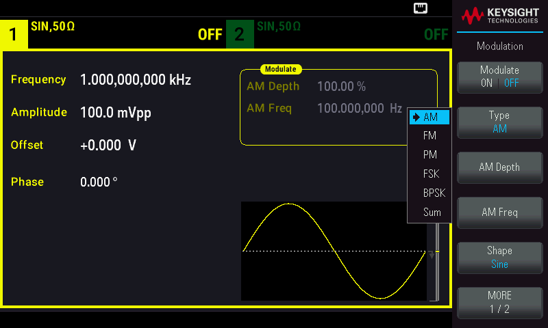
The unit supports a number of common modulations, with the modulation source selectable between different functions, PRBS sequences, external trigger input or other channel depending on the modulation chosen.
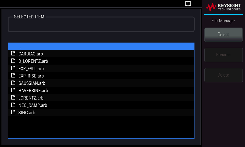
The unit comes with a number of pre-loaded arbitrary waveforms which extend on the default functions in the waveform window. Selection uses the rotary knob and the “Select” soft-key – the arrow keys are not useable.
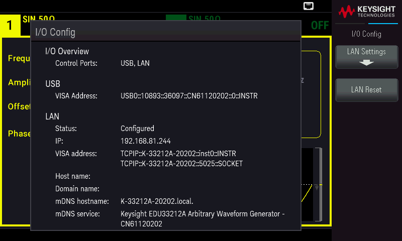
Common to all instruments is the I/O configuration menu which gives key information about the active LAN settings and allows for reconfiguration from the instrument.
Experiment: Speaking with Telephone Modems*
To make a practical demonstration of modulation, I felt it would be interesting if I could make the EDU33212A talk with a telephone line modem using its modulation input connected to a USB-UART adapter with a configuration that is compatible with V.23. As this is easier to demonstrate in the form of a video, I decided to do a bit of a guided video on it.
Experiment: Sending Radio Signals*
That’s not all though. As I’ve seen this particular unit in the background of CuriousMarc’s videos, I decided it would be good to send some voice. What better than the famous “Set SCE to Aux” line as a tribute to his Apollo series of videos. Other than that, I decide to “abuse” the memory depth and modulation capability to transmit radiofax images over the air across 15m through walls in my house to a communications receiver …
… who would have thought that this instrument could serve as a (limited) 250mW HF radio transmitter?
The results looks as follows – the hum bars across the image are likely because the receiver is powered from a switch-mode power supply with no grounding and localised interference.


See and hear this in action in my results-only video below:
As an aside, let me know in the comments which style of video you prefer!
EDU36311A Triple-Output Programmable DC Power Supply
Generally speaking, aside from the loudness of the fan, the EDU36311A is a fairly decent instrument. I find it quite usable and the choice of combination banana and binding post jacks suits education labs quite well, although does mean incompatibility with shrouded banana cables.
I still think that improvements on the front-panel interface can be made. For example, the voltage and current adjustment knobs are both non-push knobs, thus rotating them only adjusts the output at the “default” place value, requiring lifting the finger and moving to the direction pad to choose the place value. At that time, it’s probably just easier to keep using the directional pad or key in a value using the keypad. In other instruments, it’s common to use a rotary and push control where pushing toggles the place value one step at a time.
The channel selection and switching on/off logic is functional, but perhaps not as useful as the way Rohde & Schwarz usually implements it on their supplies. In their supplies, pressing a channel button toggles whether it is controlled by a master-on/off key and activates setting of parameters. From there, pressing voltage or current allows configuring the respective value. This seems intuitive to me and allows for situations where only a limited number of channels needs to be used. In the case of the Keysight, there is no concept of channel selection, so the all on/off key is a lot less useful than it would otherwise be. If a channel or two is active, pressing all on/off will turn on the remaining channel rather than shutting everything down (which is probably more appropriate if the channels were manually activated previously). The alignment of the all on/off key just above Ch2 on/off is a bit close for my liking and risks inadvertent operation.
In spite of having a USB host front-panel port, the supply makes very limited use of this, only allowing for settings to be stored and recalled. Unfortunately, the supply cannot data-log independent of a host, despite seemingly having all the hardware to do so.
The unit does have a habit of sinking quite a bit of current from external sources when the output is turned off, but at least the metering operates continuously so this can be monitored and no damage appears to occur.
Key User Interface Elements
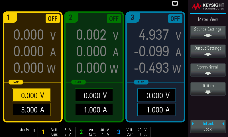
The main display shows all three channels up-front, with a lower bar which reminds users of the capabilities of the power supply. A soft-key panel flanks the right side of the screen, with status icons for connectivity towards the top-left. The channels are distinctively colour coded and metering operates continuously, even when the channel is off. In this case, the channel is sinking current from an external energy source.

A more detailed source-settings page allows access to the OVP and OCP settings, and allows for resetting the protection if it has tripped.

Sequencing of the outputs is possible, with both power-on and power-off delays.
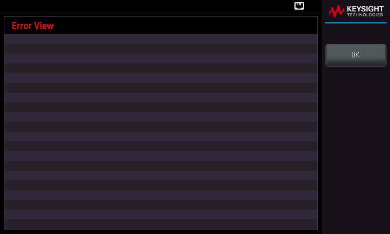
Common to all instruments is the presence of the Error View page which lists the SCPI error queue contents. This is useful for debugging SCPI programs.
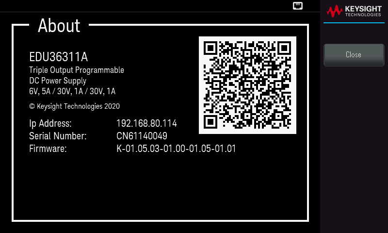
Most instruments have an About page that includes a QR code for user convenience in accessing user manual documentation.
Experiment: Full Load Test
To test the supply, I tried my best to load the supply fully. The two 30V channels were set to tracking mode and paralleled into a B&K Precision Model 8600 DC electronic load, while the remaining channel went to a 1-ohm power resistor.

The supply was able to sustain the load just fine, however, it did emit a very noticeable level of fan noise in the process.

In case you were interested – there is an alternative meter view that emphasises one channel over the other.
EDUX1052G 50MHz Two-Channel Digital Storage Oscilloscope with Wavegen
I left reviewing the DSO until last, as the EDUX1052G seems to be a bandwidth-limited oscilloscope based on the 1000 X-series which have been on the market for many years now and are very familiar to many.
Migrating from a touch-screen oscilloscope back to one with soft-keys does take a little bit of mental gymnastics but is not all that difficult. However, given the limited resolution of the screen, the soft keys and menu on the side seem to occupy precious real estate on the screen. The thing I found most pleasant was the responsiveness of the oscilloscope to knob-based inputs – it was not only fast but fluid when it comes to adjusting offsets and scales. This meant that I rarely had any unexpected overshoots during adjustments. Most standard functions performed well, even if boot-up was slow.
A key limitation seems to be the four measurements that can be displayed on the screen, as more may be desirable in some instances.

While snapshot measurements are available in that case, it does not benefit from the stability offered by statistical averaging of values, as individual values can be well off the mark.
Perhaps my biggest complaint is the cramped front panel – I find myself bumping offset knobs when adjusting scales so often that it annoys me to a great degree. Some buttons are also a little small and dedicating an extra set of vertical scale/offset knobs for Math and FFT seems to be less necessary given that Channel 1 and Channel 2 (the main inputs) already have to share one set of knobs. Analysis buttons are all clustered together towards the middle-top area, but are not visually distinctive, so it can be hard to pick them out at a first glance or by tactile feel. In all, it just seems that the panel could do with some space! The variable function green rotary knob is amongst the most important on the panel – I wonder how durable it is to constant use?
The oscilloscope overall seems very capable as an instrument of its own, in spite of its more limited bandwidth and memory depth compared to its contemporaries. Why a four-channel educational unit is not offered is curious, as the loss of the additional channels means that SPI decoding is not possible. One thing where the performance seems to be a little lacking is when dealing with file operations which can sometimes show a “spinner”.
While the probes are Keysight branded and feel sturdy, whether the switch that controls the attenuation is reliable over time is yet to be known. However, it seems that the test hook is somewhat fragile – in my short time reviewing this unit, a minor tug on the cable while hooked onto an IDC pin resulted in noticeable deformation of the hook.
Rather than introduce user interface elements directly, I feel it’s more instructive in this case to demonstrate them in experiments.
Experiment: Serial Decoding
The oscilloscope has a number of analysis features available, of which serial decoding is one major component.

To test serial decoding, I started with UART from my beacon program which just prints a repetitive message out of a USB-UART adapter.

Configured correctly for channel, rate and threshold, it is possible to get a count of frames as the oscilloscope runs. In UART mode, it is not possible to disable TX decoding – in this case, the channel was disabled and it would detect incorrect transmissions instead of being disabled.

In spite of the broad view, the memory depth and sample rate were sufficient for us to zoom in and decode each and every character correctly.

Repeating this for an Arduino running an I2C bus scan, it was possible to narrow in to the response of a single bus peripheral acknowledging its address.

The oscilloscope supports triggering on digital decode conditions, however, I have seen that it sometimes seems to miss the first I2C start condition.

Regardless, having this capability on a university lab bench is very valuable in debugging modern microcontroller-based prototypes and will be a feature appreciated by students.
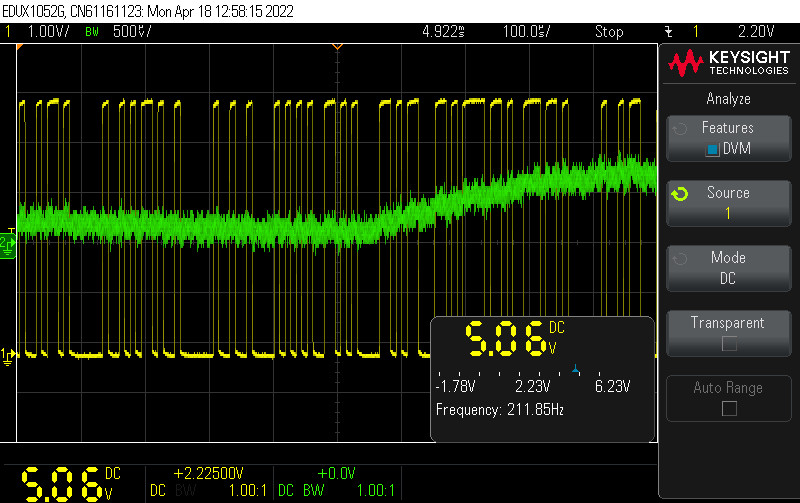
Although it doesn’t belong here, the DVM mode allows for a voltage measurement on one channel and a visual bar indicator to be displayed.
Experiment: Bode Plot (FRA) of Filters
The frequency response analysis (FRA) feature allows for the automated testing of transfer functions using the internal wavegen to provide a signal which is measured back on Channel 1 for the input and Channel 2 for the output.

The app runs on the oscilloscope itself and can be configured for frequency range, steps and measurement type.

While executing, the screen flickers and the input and output waveforms are briefly visible as the plot is built-up in real-time.
Testing a simple R-C filter of 1kΩ with 10nF capacitance which has an expected cut-off around 16kHz, then cascading two, three and finally four shows the differences in response.


Unfortunately, due to the auto-scaling, the differences aren’t as easily seen visually, but the process was very much automated and worked well. I did not see any obvious way to export this FRA data from the oscilloscope to a USB stick though.
I decided to challenge it with a random mains transformer I found on a shelf.

In this case, the response can be seen along with a self-resonance where the transformer ceases to be a transformer, in this case marked by the marker which is manually placed at the peak using the rotary knob.
Experiment: Looking for AM Radio with FFT
The FFT capability allows for frequency-domain information to be derived from the time-domain sampled data. With an open probe, it is possible to resolve broadcast AM radio signals using FFT.

In this case, one of the peaks shows ABC Radio 702kHz in Sydney at the centre of the plot, with ABC NewsRadio 630kHz visible below and ABC Radio National 576kHz below that.

While testing the annotation feature, I discovered how difficult it is to enter text on the oscilloscope using the knob and soft-keys. As a result, I feel this feature is unlikely to see much use.
Experiment: Lissajous Patterns with EDU33212A and X-Y Mode
Setting up the EDU33212A to output two sine waves with slightly different frequencies allows the formation of moving Lissajous figures. Each output from the EDU33212A is connected to the respective channel on the EDUX1052G with a BNC cable.

The display is somewhat scattered by default due to noise, but engaging the High Resolution sampling mode increases display clarity significantly.
Conclusion
The instruments are attractive on the bench and looks like a well-integrated set. The instruments feel sturdy and has a decent amount of heft. The signature 7” 800x480-pixel LCD screen occupies a large amount of real-estate and is perhaps a good feature to improve usability. However, when I saw the display in real life, my enthusiasm was dampened somewhat by backlight bleed, limited viewing angles and a flickering dot-crawl effect which is distracting. Some displayed screens also seemed to have fine detail vulnerable to these effects. Unfortunately, there is no facility to adjust backlight brightness. In spite of this, the screens were still serviceable and robust enough to handle a stray swinging connector to the face.
One less-than-obvious downside to the LCD screen is the limited real-estate remaining for front-panel buttons. As a result, the layouts of the buttons and knobs felt a bit cramped, especially for the DSO and PSU which could lead to inadvertent operation.
The user interfaces across devices are consistent in their layout of soft-keys in the case of common features, but this does draw some attention to minor differences in the way menu interactions happen as instruments have a mixture of rotary knobs with centre-click, rotary knobs without centre-click, directional-pad and numeric keypads.
Acoustically, three of the four instruments have fans thus with all instruments running, there is a noticeable background noise. The biggest offender is the PSU with a noticeable whir that could be distracting. The DSO and AWG have a more subtle rumbling motorboat hum. It is good to see that the beepers on the instruments can be disabled to ensure a quiet lab.
Specifically for the DMM, it offers a lower level of basic accuracy ranging from 0.015% to 0.027% compared to contemporaries which offer around 0.012% and has limited aperture selections rather than being able to define NPLC directly. The unit lacks a 10A current range, topping out at 3A, and lacks thermocouple temperature instead opting for thermistor-based temperature. The continuity beeper is software based with noticeable delay, and onboard capabilities for data logging are limited to 5kpts with a long sample interval of approximately 6-seconds. The USB Host port is only used for setting storage and recall.
I conducted a simple experiment to identify suitable thermistors for the temperature measurement function as the datasheet specified model was not available. The experiment concluded that most 5kΩ thermistors appear to work well.
The AWG was impressive in terms of its memory depth and two channel capabilities which enables additional capabilities when it comes to channel combining and modulation by the signal on the second channel. A key limitation with the memory means that it is not possible to have all 8Mpts in a single waveform, as each is limited to 1Mpts. Another is that such waveforms cannot be loaded across the remote interface and feedback on .arb file loading and data importing is poor, with the instrument seeming to freeze, frequently without confirmation of successful or unsuccessful loading in many cases. The lack of a dedicated trigger button results in the need to press the Trigger key twice in some cases.
By reverse-engineering the .arb file format, I was able to use the function generator to speak with telephone line modems and send modulated voice, morse code and fax images as a radio signal across the house.
In the case of the PSU, the instrument is fairly usable and the combination banana and binding post terminals makes it versatile in a lab context, although it does mean it is incompatible with shrouded banana cables which are becoming increasingly common. The front panel adjustment knobs for voltage and current have no centre click which makes adjustments awkward, requiring the use of the directional pad to control place value. The channel selection and all on/off key logic also seems a bit less functional than the arrangement I have seen in other units, and the close placement to the Channel 2 on/off key risks inadvertent operation. Similarly to the DMM, the USB port is only used for settings storage and loading, as the unit lacks data logging and screenshot capabilities onboard.
Finally, the DSO showed performance consistent with a competent and mature product. The user interface was fluid and the response of the knobs is excellent. The limited real-estate of the screen is perhaps not best utilised with the fixed bar on the right side where the soft-buttons ordinarily appear and the limited memory depth is unlikely to be a major issue for simple lab exercises. Instead, the key issue was the cramped operation panel which made bumping offset knobs when adjusting scale knobs a likely occurrence. Allocating vertical scale and offset knobs for math/FFT traces also seemed unnecessary as Channel 1 and 2 already share a set. Some keys were also somewhat small for my liking and file operations can sometimes be slow, resulting in a spinner appearing, Another key finding is that the test hook on the probes do not seem all that robust, having bent in a minor cable “tug” incident. In the undergraduate education context, a 50MHz bandwidth limit is not a major issue.
The DSO proved its value, performing UART and I2C decoding competently. The FRA feature was able to construct bode plots automatically, even if they could not be saved on the unit. The FFT feature was able to identify AM radio stations while X-Y mode was able to fluidly display Lissajous patterns generated with the use of the AWG.
On the whole, the instruments were not without their own compromises, but none of them seem particularly a deal-breaker in the context of an undergraduate tertiary education lab. Instead, the instruments are venturing into a market where no mainstream manufacturer has previously chosen to explore and trying to offer a good value offering backed by Keysight’s reputation and experience. In the case of the EDUX1052G DSO, the experience definitely shows in the fluidity of the interface and feature set. The EDU33212A AWG provides levels of memory depth and modulation capability that would previously not be found on an undergraduate university lab bench. Similarly, the EDU34450A DMM is offering 5.5-digits at a price which undercuts practically most of the market while remaining competent at the things that matter. Finally, the EDU36311A PSU meets the needs of most lab benches by providing output that can be configured into a split-rail supply with an auxiliary rail while providing both banana and binding post connectivity options for flexibility.
---
This post is part of the Keysight Smart Bench Essentials RoadTest Review.
Direct links to detailed blogs:
- Keysight SBE In-Depth – Ch1: The Need for Smarter Benches?
- Keysight SBE In-Depth – Ch2: Unboxing^4 & Design Features
- Keysight SBE In-Depth – Ch3: Initial Setup & Documentation
- Keysight SBE In-Depth – Ch4: On-the-Bench User Experience
- Keysight SBE In-Depth – Ch5: Connected to the LAN
- Keysight SBE In-Depth – Ch6: PathWave BenchVue Oscilloscope, Power Supply, Digital Multimeter & Function Generator
- Keysight SBE In-Depth – Ch7: Keysight BenchVue Test Flow Automation
- Keysight SBE In-Depth – Ch8: Instrument Performance Tests
- Keysight SBE In-Depth – Ch9: Peeking Under the Covers

