


For my Arduino Day 2021 Project I built a controller for my solar powered crawlspace vent fan. I provided an overview of the project in a previous post - Arduino Day 2021 Project Intro .
The following documents my implementation.
Bill of Material:
Product Name | Manufacturer | Quantity |
|---|---|---|
| Arduino Nano 33 IoT | Arduino | 1 |
| LM2596 Buck Converter Module | 1 | |
| HW-803 5V Relay Module | 1 | |
| BME280 Temperature Sensor Board | 2 | |
| M5StickC Plus | M5Stack | 1 |
| Raspberry Pi 4 2GB | Raspberry Pi | 1 |
| SPDT Slide Switch | 1 | |
| Molex Mini-Fit Jr 2 pin 18-24 AWG Connector Pair | Molex | 1 |
| Weatherproof Junction Box 3.9 X 3.9 X 2.8 inch | LeMoTech | 1 |
| Louver Vent Hood 6 inch | Lambro Industries | 2 |
Additional Parts:
Product Name |
|---|
| 3D Printed Plate |
| ProtoBoard |
| Wires |
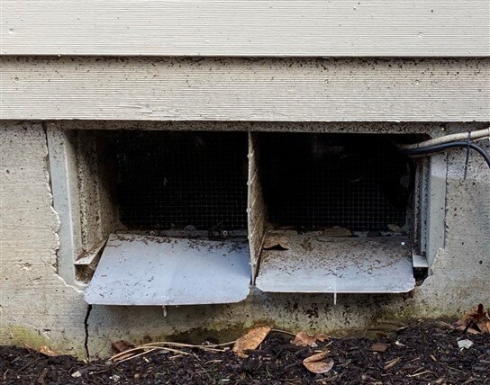
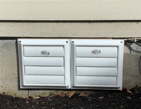
Vent Louvers
This is the non-electronic part of the project. I found a couple of 6" Louver Vent Hoods and built a wooden frame that I attached to the foundation vent using a couple of magnetic cabinet latches. I thought it would improve the look and it provides some form of passive automatic closure when the fan isn't running.
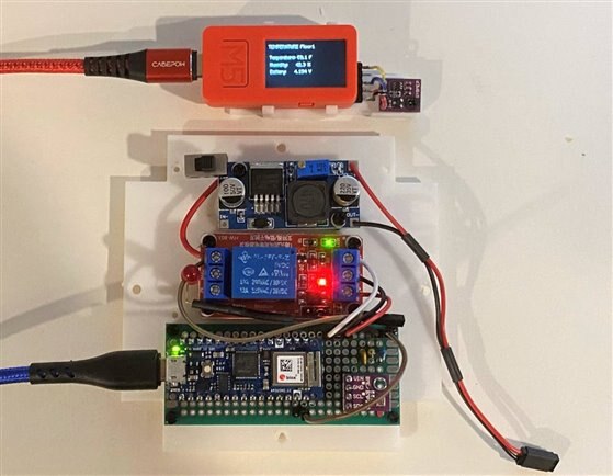
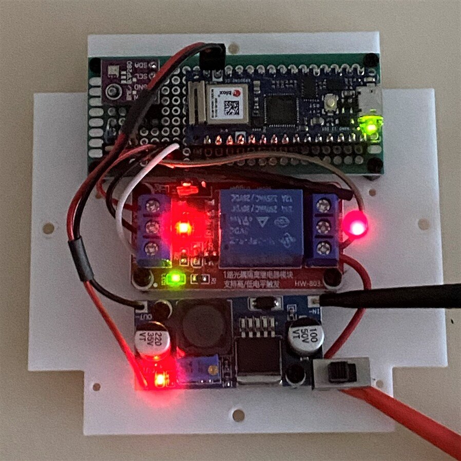
Proto board assemblies
I printed a mounting plate for the boards that are going into the weatherproof enclosure. I have them wired up so that I could start software development. I don't have the 20V power connectors attached yet. We are having a typical Oregon spring - cold and wet. I may end up doing my project demo indoors and deploy the circuit when it gets sunnier and drier. I have a portable 20V power supply that I can use to emulate the solar panel and I've put an LED on the relay output to test the switching of the 20V supply. For initial programming and testing I'm not using the 20V input (i.e. not using the buck converter, though I've set the 5V output and tested that separately with 20-25V at the input). I'm also using 5V as "solar voltage" for the A/D measurement. When I get to final test, I'll use the 20V circuits.
The remote sensor that I'm using was built for a different project. It uses an M5StickC Plus module with the same BME280 sensor that I'm using for the local temperature. I had posted about my experience with the M5StickC earlier M5StickC Modules . The Plus module has a larger display and a higher capacity battery. I will probably switch to using a more power optimized remote sensor later as this sensor will be battery powered and inconveniently located under the house..
The modules from top to bottom
- M5StickC Plus with BME280
- LM2596 Buck Converter
- HW-803 5V Opto-isolated Relay
- Nano 33 IoT with BME280 on protoboard
Node-RED MQTT Dashboard
For this project I am using MQTT for monitoring and control, so I decided to use a Node-RED MQTT Dashboard. I found a very useful set of tutorials by Random Nerd Tutorials for setting up a Mosquito MQTT broker (server) on a Raspberry Pi using Node-RED. This requires installing 3 components which are covered in the following tutorials:
I'm using an RPi4 2GB for the MQTT Server. I run it headless, 24/7 with UPS backup.
The elements that I want to monitor on the dashboard:
- Local Temperature (outside crawlspace - local to the controller - this is the outside temperature that I'll use to turn the fan on and off)
- Local Humidity
- Solar Voltage (the voltage from the solar panel)
- Relay State (I am using the normally open contact, so the default state is off - no fan power)
- Remote Temperature (temperature inside crawlspace)
- Remote Humidity
The elements that I want to control from the dashboard:
- Set Temperature (the local temperature at which the fan will turn on - defaults to 32 F)
- Override Enable (when enabled, the relay will be controlled by Relay Set)
- Relay Set (turn relay on/off if Override is enabled)
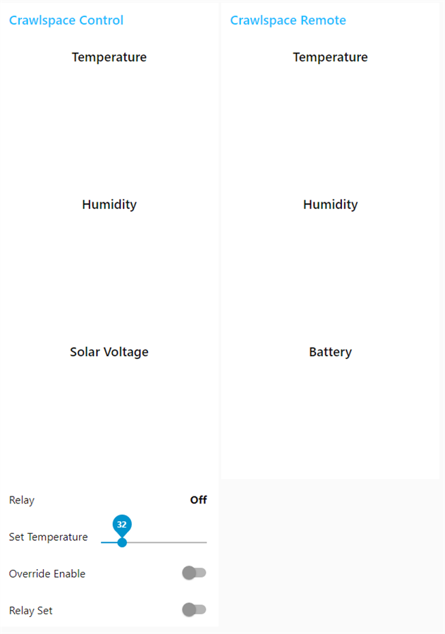
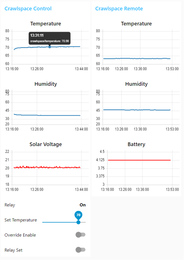
Here is the dashboard I implemented (I'm a Node-Red noob, so I kept it simple):
This is the dashboard in reset state (charts are not populated)
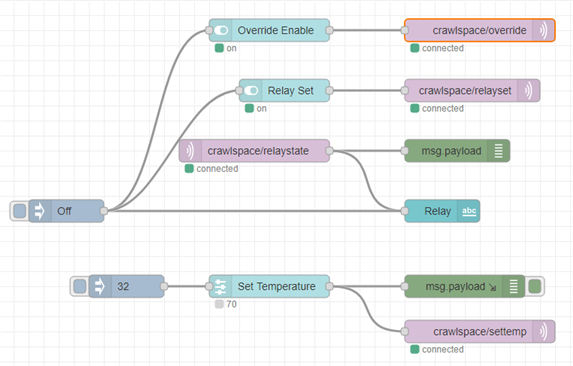
The Node-RED flow to implement the MQTT interaction with the dashboard
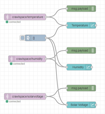
Node-RED Subscribe Flow for data charting
This flow has 4 elements for each sensor data input:
- mqtt in - receives data (subscribes to topics) from the Nano 33 IoT
- inject - to reset initial state (clear chart data)
- debug - provides received data logging for debug
- chart - line chart of received data
Example for Temperature data:
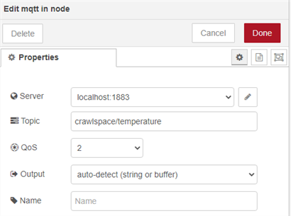
Properties:
- Server - the Rpi4 is both web host and MQTT server so using localhost on standard port 1883
- Topic - this is the subscribed topic that is being published by the Nano 33 IoT
- QoS - 2 guarantees that there is only a single response received
- Output - autodetect data type
- Name - optional, if left blank it will take the topic name

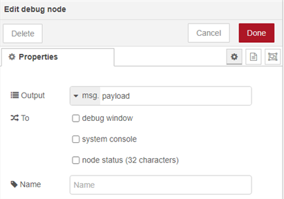
Properties:
- Output - this could be the msg payload, the complete message object, or an javascript expression
- To - selects where to put the output, defaults to debug window - but I only select when debugging to reduce clutter
- Name - optional, if left blank it will take the output name

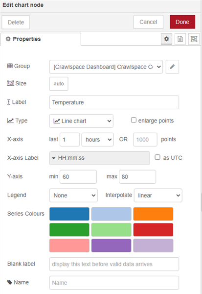
Properties: most are obvious in context
- Group - this selects the particular dashboard and tab to place the chart
- Size - you can manually resize if desired
- Type - Chart types
- Line
- Bar
- Bar (H)
- Pie
- Polar area
- Radar
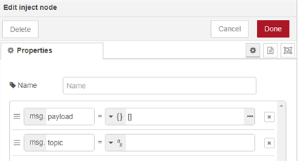
Properties: Lots of options here. I use the following:
- Blank data array {[]} to clear out the chart data.
- Text string to initialize value (e.g. On/Off for switches)
- Numerical data to initialize (e.g. 32 for slider)
Node-RED Subscribe/Publish Flow for monitor/control
This flow has the additional elements:
- mqtt out - publishes topics
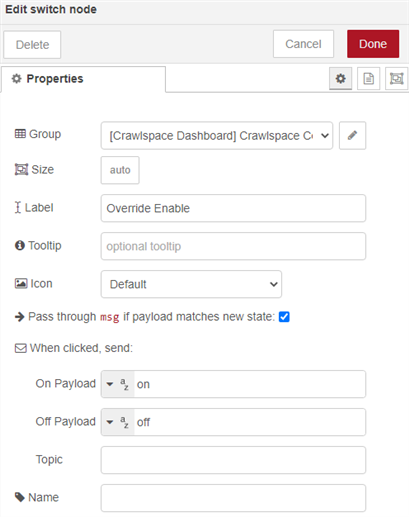
- switch - to set Override Enable and Relay Set on/off values
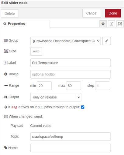
- slider - sets the control temperature value
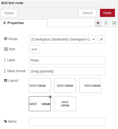
- text - displays Relay State on dashboard
Example for Override Enable:
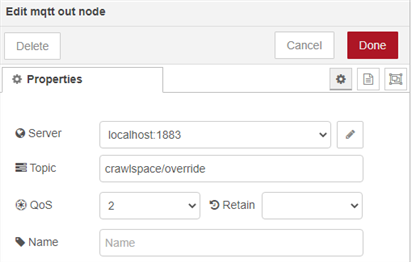

Example for Override Enable:


Dashboard Display while running final program
This is still running indoors (not deployed), but using the 20V Portable Power Supply. The 20V (Solar Voltage) measurement is still somewhat noisy, I'll need to take a look at that. The Remote Battery reading is high because I'm running on a USB battery bank (LiPo battery is in charge mode). The Remote is in a colder room in the house (not the crawlspace). The Relay is on because the temperature is above the Set Temperature.
20V Test Setup
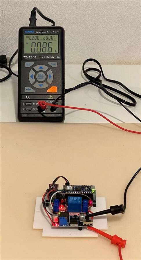
The LED on the terminal block on the right side of the relay module is the proxy for the vent fan (running off the switched 20V with a 1.2K ohm series resistor).
Arduino Control Program
The program startup sequence:
- Connect to WiFi
- Connect to MQTT Server (RPi4)
- Publish
- Local Temperature
- Local Humidity
- Solar Voltage
- Relay State
- Subscribe
- Set Temperature
- Override Enable
- Relay Set
Program defaults:
- Relay State = 0
- Set Temperature = 32 F
- Override Enable = 0
- Relay Set = 0
Here is debug serial output of the startup (currently publishes every 10 seconds for debug - probably extend it to 60 seconds when I deploy):
This output was captured prior to switching to the 20V setup (no USB connection for serial output in that case).
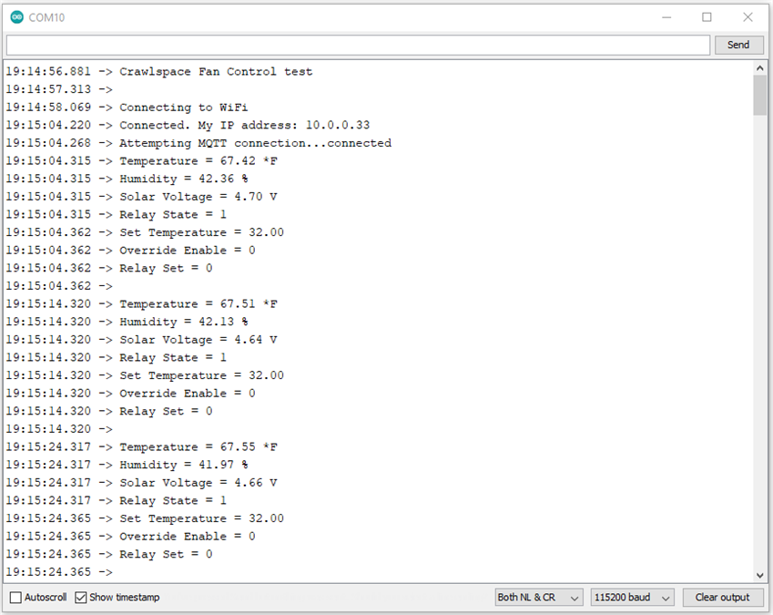
Relay State = 1 because the Temperature is above the Set Temperature (32 F)
Solar Voltage ~4.7V (this is 5V that comes from the USB - it's quite noisy, I'll need to check it at 20V)
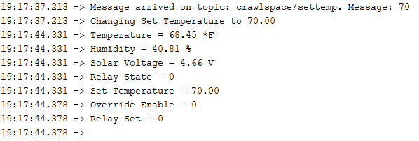
Change the Set Temperature to 70 F from dashboard
Message is received and Set Temperature is changed
Relay State = 0
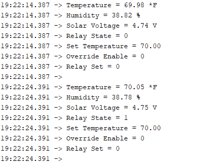
After about 5 more minutes of operation the Temperature rises to above 70 F and Relay State = 1
Program Code
Crawlspace_Fan_Control.ino
/*
  MQTT Client for Crawlspace Vent Fan


  the arduino_secrets.h file:
  #define SECRET_SSID ""    // network name
  #define SECRET_PASS ""    // network password
  #define SECRET_MQTT_USER "public" // broker username - not used
  #define SECRET_MQTT_PASS "public" // broker password - not used


  created 14 March 2021
  by Ralph Yamamoto
*/
#include <avr/dtostrf.h>
#include <Wire.h>
#include <SPI.h>
#include <Adafruit_Sensor.h>
#include <Adafruit_BME280.h>


#include <WiFiNINA.h>
#include <PubSubClient.h>
#include "arduino_secrets.h"


#define WAIT_SERIAL true //wait for serial to start
#define DEBUG true  //set to true for debug output, false for no debug output
#define DEBUG_SERIAL if(DEBUG)Serial


#define relayPin 2
#define solarvoltagePin A7


#define ADC_AVERAGES 10


Adafruit_BME280 bme; // I2C


float tempBME = 0.0;
float humBME = 0.0;
float voltSolar = 0.0;
float setTemp = 32.0;  //default


uint32_t readAccumulator = 0;
unsigned long delayTime = 1000;


int relayState = 0;
int relayOverride = 0;
int relaySet = 0;


// initialize WiFi connection:
WiFiClient wifi;
//MqttClient mqttClient(wifi);
PubSubClient client(wifi);
long lastMsg = 0;
char msg[50];
int value = 0;


// details for MQTT client:
const char* mqtt_server = "10.0.0.234";


void callback(char* topic, byte* message, unsigned int length) {
  DEBUG_SERIAL.print("Message arrived on topic: ");
  DEBUG_SERIAL.print(topic);
  DEBUG_SERIAL.print(". Message: ");
  String messageTemp;

  for (int i = 0; i < length; i++) {
    DEBUG_SERIAL.print((char)message[i]);
    messageTemp += (char)message[i];
  }
  DEBUG_SERIAL.println();


  // If a message is received on the topic crawlspace/override, you check if the message is either "on" or "off".
  // Changes the output state according to the message
  if (String(topic) == "crawlspace/override") {
    DEBUG_SERIAL.print("Changing override to ");
    if(messageTemp == "on"){
      DEBUG_SERIAL.println("on");
      relayOverride = 1;
    }
    else if(messageTemp == "off"){
      DEBUG_SERIAL.println("off");
      relayOverride = 0;
    }
  }
  // If a message is received on the topic crawlspace/relayset, you check if the message is either "on" or "off".
  // Changes the output state according to the message
  if (String(topic) == "crawlspace/relayset") {
    DEBUG_SERIAL.print("Changing relayset to ");
    if(messageTemp == "on"){
      DEBUG_SERIAL.println("on");
      relaySet = 1;
    }
    else if(messageTemp == "off"){
      DEBUG_SERIAL.println("off");
      relaySet = 0;
    }
  }
  // If a message is received on the topic crawlspace/settemperature, you check if the message is either "on" or "off".
  // Changes the output state according to the message
  if (String(topic) == "crawlspace/settemp") {
    DEBUG_SERIAL.print("Changing Set Temperature to ");
    setTemp = atof(messageTemp.c_str());
    DEBUG_SERIAL.println(setTemp);
  }
}


void setup() {
  //set relayPin as output
  pinMode(relayPin, OUTPUT);
  digitalWrite(relayPin, LOW);  //set to NC

  // initialize serial:
  DEBUG_SERIAL.begin(9600);
  // wait for serial monitor to open:
  if(WAIT_SERIAL)while (!Serial);  // time to get serial running - take out after debug
  DEBUG_SERIAL.println(F("Crawlspace Fan Control test"));


  unsigned status;

  // default settings
  // (you can also pass in a Wire library object like &Wire2)
  status = bme.begin(0x76);
  if (!status) {
      DEBUG_SERIAL.println("Could not find a valid BME280 sensor, check wiring, address, sensor ID!");
      DEBUG_SERIAL.print("SensorID was: 0x"); DEBUG_SERIAL.println(bme.sensorID(),16);
      DEBUG_SERIAL.print("        ID of 0xFF probably means a bad address, a BMP 180 or BMP 085\n");
      DEBUG_SERIAL.print("   ID of 0x56-0x58 represents a BMP 280,\n");
      DEBUG_SERIAL.print("        ID of 0x60 represents a BME 280.\n");
      DEBUG_SERIAL.print("        ID of 0x61 represents a BME 680.\n");
      while (1);
  }


  DEBUG_SERIAL.println();


  // initialize WiFi, if not connected:
  while (WiFi.status() != WL_CONNECTED) {
    DEBUG_SERIAL.print("Connecting to ");
    DEBUG_SERIAL.println("WiFi");   //could print SSID
    WiFi.begin(SECRET_SSID, SECRET_PASS);
    delay(2000);
  }
  // print IP address once connected:
  DEBUG_SERIAL.print("Connected. My IP address: ");
  DEBUG_SERIAL.println(WiFi.localIP());


  // setup the MQTT client:
  client.setServer(mqtt_server, 1883);
  client.setCallback(callback);


}


void reconnect() {
  // Loop until we're reconnected
  while (!client.connected()) {
    Serial.print("Attempting MQTT connection...");
    // Attempt to connect
    if (client.connect("Nano33IoTClient")) {
      Serial.println("connected");
      // Subscribe
      client.subscribe("crawlspace/override");
      client.subscribe("crawlspace/relayset");
      client.subscribe("crawlspace/settemp");
    } else {
      Serial.print("failed, rc=");
      Serial.print(client.state());
      Serial.println(" try again in 5 seconds");
      // Wait 5 seconds before retrying
      delay(5000);
    }
  }
}


void printValues() {
    DEBUG_SERIAL.print("Temperature = ");
    DEBUG_SERIAL.print(bme.readTemperature()*1.8 + 32);
    DEBUG_SERIAL.println(" *F");


//    DEBUG_SERIAL.print("Pressure = ");
//    DEBUG_SERIAL.print(bme.readPressure() / 100.0F);
//    DEBUG_SERIAL.println(" hPa");


    DEBUG_SERIAL.print("Humidity = ");
    DEBUG_SERIAL.print(bme.readHumidity());
    DEBUG_SERIAL.println(" %");


    DEBUG_SERIAL.print("Solar Voltage = ");
    DEBUG_SERIAL.print(voltSolar);
    DEBUG_SERIAL.println(" V");


    DEBUG_SERIAL.print("Relay State = ");
    DEBUG_SERIAL.println(relayState);


    DEBUG_SERIAL.print("Set Temperature = ");
    DEBUG_SERIAL.println(setTemp);

    DEBUG_SERIAL.print("Override Enable = ");
    DEBUG_SERIAL.println(relayOverride);


    DEBUG_SERIAL.print("Relay Set = ");
    DEBUG_SERIAL.println(relaySet);


    DEBUG_SERIAL.println();
}


void loop() {
  // if not connected to the broker, try to connect:
    if (!client.connected()) {
      reconnect();
    }
    client.loop();

    long now = millis();
    if (now - lastMsg > 10000) {
      lastMsg = now;


    // publish temperature
      // Convert the value to a char array
      char tempString[8];
      tempBME = bme.readTemperature()*1.8 + 32;
      dtostrf(tempBME, 6, 2, tempString);
      // start a new message on the topic:
      client.publish("crawlspace/temperature", tempString);

    // publish humidity
      // Convert the value to a char array
      char humString[8];
      humBME = bme.readHumidity();
      dtostrf(humBME, 6, 2, humString);
      // start a new message on the topic:
      client.publish("crawlspace/humidity", humString);

    // publish solar panel voltage
      // Convert the value to a char array
      char voltString[8];
      readAccumulator = 0;
      for (int i = 0; i < ADC_AVERAGES; ++i)
        readAccumulator += analogRead(solarvoltagePin);
      voltSolar = (readAccumulator * 3.3 * 10 / 1024) / ADC_AVERAGES;
      dtostrf(voltSolar, 5, 2, voltString);
      // start a new message on the topic:
      client.publish("crawlspace/solarvoltage", voltString);


    //control relay
      if (relayOverride == 1) {
        if (relaySet == 1) {
          digitalWrite(relayPin, HIGH);
          relayState = 1;
        } else {
          digitalWrite(relayPin, LOW);
          relayState = 0;
        }
      } else {
        if (tempBME > setTemp){
          digitalWrite(relayPin, HIGH);
          relayState = 1;
        }
        else{
          digitalWrite(relayPin, LOW);
          relayState = 0;
        }
      }
      // publish relayState
      if (relayState == 1) {
        client.publish("crawlspace/relaystate", "On");
      }else{
        client.publish("crawlspace/relaystate", "Off");
      }


      // print values
      printValues();

    }


}
Demo Video
Demo showing the interaction between the MQTT Dashboard and the Nano 33 IoT. The operational delay is due to the 10 second update rate.
Summary
Well, that's my Arduino Day Project for 2021. I made a silly mistake when loading the contacts of the Mini Fit JR connectors (I loaded the wrong sex into the housings - had them reversed). I'll blame pandemic brain fog which in reality is probably true. I can't manage to get the contacts extracted, so I'll need to make another set. So, another reason to wait for it to dry out before I deploy/mount this outside. I've measured the solar panel and fan setup, so there shouldn't be any issues. The max voltage that I've measured is about 21.5V and the max current is less than 500mA (surprised me that it was that low, but I can't read the fan label to check the spec).
The feature that I would also like to incorporate before deploying is OTA (over the air update). I've done this with ESP32s and I'm sure there is an equivalent process for WiFi Arduinos.
And there is plenty of space left:

Top Comments