I`m currently making some proto circuits and I would love some feed back/Ideas etc.
All these circuits will connect to Arduino or Arduino compatible devices.
Anyone have time to help out with some reviews?
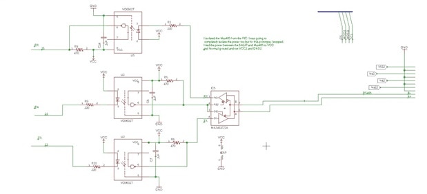
First circuit is a 4-20ma board
I`m currently making some proto circuits and I would love some feed back/Ideas etc.
All these circuits will connect to Arduino or Arduino compatible devices.
Anyone have time to help out with some reviews?
First circuit is a 4-20ma board