element14 Community
element14 Community
    Register Log In
  • Site
  • Search
  • Log In Register
  • About Us
  • Community Hub
    Community Hub
    • What's New on element14
    • Feedback and Support
    • Benefits of Membership
    • Personal Blogs
    • Members Area
    • Achievement Levels
  • Learn
    Learn
    • Ask an Expert
    • eBooks
    • element14 presents
    • Learning Center
    • Tech Spotlight
    • STEM Academy
    • Webinars, Training and Events
    • Learning Groups
  • Technologies
    Technologies
    • 3D Printing
    • FPGA
    • Industrial Automation
    • Internet of Things
    • Power & Energy
    • Sensors
    • Technology Groups
  • Challenges & Projects
    Challenges & Projects
    • Design Challenges
    • element14 presents Projects
    • Project14
    • Arduino Projects
    • Raspberry Pi Projects
    • Project Groups
  • Products
    Products
    • Arduino
    • Avnet Boards Community
    • Dev Tools
    • Manufacturers
    • Multicomp Pro
    • Product Groups
    • Raspberry Pi
    • RoadTests & Reviews
  • Store
    Store
    • Visit Your Store
    • Choose another store...
      • Europe
      •  Austria (German)
      •  Belgium (Dutch, French)
      •  Bulgaria (Bulgarian)
      •  Czech Republic (Czech)
      •  Denmark (Danish)
      •  Estonia (Estonian)
      •  Finland (Finnish)
      •  France (French)
      •  Germany (German)
      •  Hungary (Hungarian)
      •  Ireland
      •  Israel
      •  Italy (Italian)
      •  Latvia (Latvian)
      •  
      •  Lithuania (Lithuanian)
      •  Netherlands (Dutch)
      •  Norway (Norwegian)
      •  Poland (Polish)
      •  Portugal (Portuguese)
      •  Romania (Romanian)
      •  Russia (Russian)
      •  Slovakia (Slovak)
      •  Slovenia (Slovenian)
      •  Spain (Spanish)
      •  Sweden (Swedish)
      •  Switzerland(German, French)
      •  Turkey (Turkish)
      •  United Kingdom
      • Asia Pacific
      •  Australia
      •  China
      •  Hong Kong
      •  India
      •  Korea (Korean)
      •  Malaysia
      •  New Zealand
      •  Philippines
      •  Singapore
      •  Taiwan
      •  Thailand (Thai)
      • Americas
      •  Brazil (Portuguese)
      •  Canada
      •  Mexico (Spanish)
      •  United States
      Can't find the country/region you're looking for? Visit our export site or find a local distributor.
  • Translate
  • Profile
  • Settings
Azure Sphere Starter Kit
  • Products
  • Dev Tools
  • Avnet Boards Community
  • Azure Sphere Starter Kit
  • More
  • Cancel
Azure Sphere Starter Kit
Blog Azure Sphere - Tips to max-out your Starter Kit hardware! (Part 1)
  • Blog
  • Forum
  • Documents
  • Events
  • Polls
  • Files
  • Members
  • Mentions
  • Sub-Groups
  • Tags
  • More
  • Cancel
  • New
Join Azure Sphere Starter Kit to participate - click to join for free!
  • Share
  • More
  • Cancel
Group Actions
  • Group RSS
  • More
  • Cancel
Engagement
  • Author Author: peterfenn
  • Date Created: 7 Aug 2019 1:50 PM Date Created
  • Views 2781 views
  • Likes 8 likes
  • Comments 12 comments
  • azure sphere kit
  • mikrobus click
  • oled
  • azurespherech
  • azure sphere
  • azure sphere mt3620 starter kit
  • oled display
  • azuresphkt
  • azure sphere starter kit
  • mt3620
  • pmod
Related
Recommended

Azure Sphere - Tips to max-out your Starter Kit hardware! (Part 1)

peterfenn
peterfenn
7 Aug 2019

  • Avnet Starter Kit use of MT3620 ISUs (serial interface blocks)
  • Starter Kit use of GPIOs
  • Starter Kit unpopulated Expansion Connectors
    • J11 3-pin header
    • J13 UART/BLE Connector
    • J7  OLED Display Connector
  • For more Information...

image


Avnet Starter Kit use of MT3620 ISUs (serial interface blocks)


The three ISUs accessible on your Starter Kit are "preconfigured" in that the ISU signals pinned-out of the module were limited for the support of:

  • ISU0: UART0 (4 IOs)
  • ISU1: SPI1 (5 IOs)
  • ISU2: I2C2 (2 IOs)


It is possible however within these pinout limitations, to assign the ISU functions as follows:

  • ISU0: use for I2C or UART or SPI
  • ISU1: use for I2C or UART or SPI
  • ISU2: use for I2C only


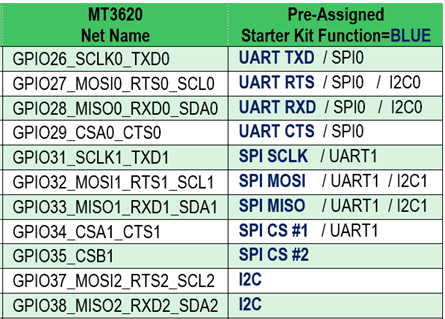
The table below shows in blue text the functions these ISUs are "assigned" to on the Starter Kit, followed by the alternative interfaces that can be supported by these pins

image


The serial interface capabilities of the ISUs are documented at:

https://docs.microsoft.com/en-us/azure-sphere/hardware/mt3620-product-status


Starter Kit use of GPIOs


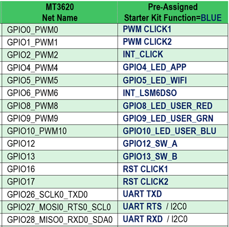
The table below shows in blue text the functions that other GPIOs have been assigned to on the Starter Kit

image


Starter Kit unpopulated Expansion Connectors


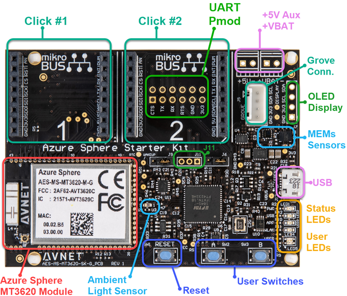
Additional expansion options are accessible via three unpopulated connector sites on your Starter Kit (see green-colored call-outs in the board view above)


J11 3-pin header

This pins-out the TXD outputs of the MT3620's two M4-dedicated UARTs, typically for M4 application debugging (via a USB to serial cable)
but can alternatively be assigned for user-defined GPIO functions

image

A good example where an M4-dedicated UART is used for console output (debugging info) for an application, is provided in the UART_RTApp_MT3620_BareMetal sample application from Microsoft
https://github.com/Azure/azure-sphere-samples/tree/master/Samples/UART/UART_RTApp_MT3620_BareMetal

In other real-time samples, the application polls when data is sent via the UART. In this application however memory buffers are used for send and receive of data, and interrupts rather than polling are used.

(This approach makes the UART_RTApp sample a useful starting-point for non-blocking applications)


J13 UART/BLE Connector

An unpopulated 2x6 connector site is located under Click Socket #2. Designed to accommodate a 2x6 right-angle female socket,
the pinout is compatible with a subset of Pmod peripheral boards available from Digilent and other suppliers

Notes:

  • The four (ISU0) UART pins and GPIO2 are shared with both Click sockets
  • GPIO1 and GPIO17 are shared only with Click socket #2
  • The WAKEUP input pin allows an external device to wake-up the MT3620 SoC
  • All signalling on this connector is at 3.3V levels

image

image

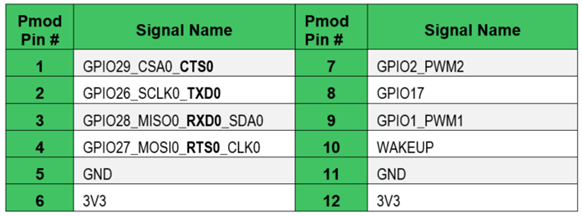
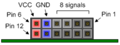
Right-angle Pmod connector (viewed from board edge)


J7  OLED Display Connector

The pinout and corner mechanical mounting hole were designed to accommodate one of many 3rd-party 128x64 I2C OLED graphic displays

Make sure to select an OLED display with GND and VCC in the correct order! (Some low-cost OLED displays reverse the sequence of the GND and VCC pins!)

This connector site can alternatively be used for easy attachment of an external sensor to the I2C bus

image

image

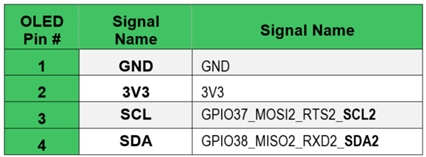
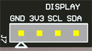
OLED Display Connector (viewed from above the board edge)


For more Information...


For detailed information on your Starter Kit's hardware capabilities, refer to the following documents:

  • Hardware User Guide - Azure Sphere MT3620 Starter Kit
  • Block Diagram - Azure Sphere MT3620 Starter Kit
  • AES-MS-MT3620-SK-G_SCH_2019-07-03
  •      Mediatek MT3620 Datasheet and MT3620 Product Brief documents

     http://avnet.me/mt3620-datasheet


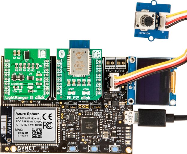
Take a look at the Avnet Azure Sphere Starter-Kit: Advanced Tutorial for a comprehensive application example that adds an inexpensive OLED display and Click relay board, and offers rapid implementation via a pre-engineered application template for Azure IoT Central dashboard, remote control of LEDs, relays and OLED messages, plus email notifications, etc


image


Part 2 of this Tips to max-out your Starter Kit hardware! series is available here:

http://avnet.me/azphere-kit-tips-2

  • Sign in to reply

Top Comments

  • peterfenn
    peterfenn over 6 years ago in reply to stevesmythe +2
    Steve, Thanks for pointing this out. The Grove connector on the Azure Sphere Starter Kit is committed for I2C use only For access to ADC inputs you will need to make use of a Click board rather than Grove…
  • stevesmythe
    stevesmythe over 6 years ago +1
    peterfenn The photo at the bottom of this article shows a Grove rotary angle sensor plugged into the Grove socket on the Azure Sphere board. This would require an ADC channel to read the voltage. Is this…
  • peterfenn
    peterfenn over 6 years ago in reply to stevesmythe +1
    Steve, If looking for a rotary control, have you considered a rotary encoder? There are a couple of inexpensive Click boards that encode the position of the control, some with a ring of LEDs to provide…
  • jgroman
    jgroman over 5 years ago in reply to pmossel

    pmossel Peter, you can find some OLED example code plus a repo with complete projects here: Universal monochrome OLED display driver for Azure Sphere (with examples)

    • Cancel
    • Vote Up 0 Vote Down
    • Sign in to reply
    • More
    • Cancel
  • xeonaj
    xeonaj over 5 years ago in reply to pmossel

    Thank You Sir!

    I didn't know these things!

    • Cancel
    • Vote Up 0 Vote Down
    • Sign in to reply
    • More
    • Cancel
  • pmossel
    pmossel over 5 years ago in reply to xeonaj

    Electrostatic discharge. Static electricity is a charge that is built up in materials such as clothes or fabrics. If the charge is discharged onto a material that is sensitive to charge such as MOSFET chips, permanent damage may occur.


    The risk of damage due to ESD  for voltage regulator integrated circuits is somewhat less than for CPU's and memory but it nevertheless is advised to work in an ESD safe environment with boards such as the MT3620 which are not in an enclosure.


    A simple rule to be safe from ESD damage is by touching a large metal object such as a workbench or a computer enclosure prior to touching a circuit board.

    • Cancel
    • Vote Up 0 Vote Down
    • Sign in to reply
    • More
    • Cancel
  • xeonaj
    xeonaj over 5 years ago in reply to peterfenn

    What is ESD?

    • Cancel
    • Vote Up 0 Vote Down
    • Sign in to reply
    • More
    • Cancel
  • peterfenn
    peterfenn over 5 years ago in reply to pmossel

    Soldering of the OLED display is not the issue, some of the Starter Kits have had their 3.3V regulators damaged by ESD.
    Take precautions to reduce the chance of ESD damage (eg. use a grounding strap) when handling the board 

    • Cancel
    • Vote Up 0 Vote Down
    • Sign in to reply
    • More
    • Cancel
>
element14 Community

element14 is the first online community specifically for engineers. Connect with your peers and get expert answers to your questions.

  • Members
  • Learn
  • Technologies
  • Challenges & Projects
  • Products
  • Store
  • About Us
  • Feedback & Support
  • FAQs
  • Terms of Use
  • Privacy Policy
  • Legal and Copyright Notices
  • Sitemap
  • Cookies

An Avnet Company © 2025 Premier Farnell Limited. All Rights Reserved.

Premier Farnell Ltd, registered in England and Wales (no 00876412), registered office: Farnell House, Forge Lane, Leeds LS12 2NE.

ICP 备案号 10220084.

Follow element14

  • X
  • Facebook
  • linkedin
  • YouTube