


Raspberry PIO stepper library (pio_stepper_lib) is a C++ library that runs stepper motors in PIO state machines. It's intended to be easy to integrate and use in Pico projects.
Check Raspberry PIO stepper library documentation - 1: intro, set up project and simple example to get a motor running. and Raspberry PIO stepper library documentation - 2: advanced example with notification for tighter execution control . This exercise builds upon that example.
This exercise uses the library to control 2 motors. A few scenarios are shown:
- all commands run in sequence
- each motor picking its commands and run them all in parallel.
|
you don't need stepper motors or driver ICs to test this. If you have an oscilloscope, you can see what's happening.. Probe these pins:
In this exercise, I probed GPIO5 and GPIO7. |
Design Approach
This example uses the same classes as exercise 2. All changes are in the example code.
initialisation:
I created a container to hold the two motors. This is convenient when the same action has to be done on both motors. And it's also a starting point for running more than 2 steppers.
// TODO: adapt to your  board design
const uint motor1_dir = 4U; // implies that step is gpio 5
const uint motor2_dir = 6U; // implies that step is gpio 7

using motor_t = stepper::stepper_callback_controller;
std::array<motor_t, 2> motors {{{pio0, 0}, {pio0, 1}}};
I used PIO 0, state machine 0 and 1. Any combination works, as long as you have one motor per available state machine.
Each PIO that's used, needs to be programmed, and state machines set up:
void init_pio() {
    // program the pio used for the motors
    // do this only once per used pio
    motor_t::pio_program(pio0); // not needed if all sms run on pio1
    // motor_t::pio_program(pio1); // not needed if all sms run on pio0

    // individual settings
    motors[0].pio_init(motor1_dir, clock_divider);
    motors[1].pio_init(motor2_dir, clock_divider);
    // common settings
    // initialise and enable the motor state machine
    for (auto &m: motors) {
        m.register_pio_interrupt(0, true);
        m.enable(true);
        // and the notification, for demo purpose
        m.on_complete_callback(on_complete);
    }
}
Notification, and flag that a job has finished:
I created a container that gets the count of steps to do per motor. In the callback, I decrease the counter of a motor every time it flags a job done.
The same callback is used for both motors.
std::array<volatile size_t, motors.size()> commands_per_motor;
void on_complete(const motor_t &stepper) {
    size_t index = 0U;
    for (auto &m: motors) {
        if (&m == &stepper) {
            commands_per_motor[index] =  commands_per_motor[index] - 1;
            printf("motor %d executed command\n", index + 1);
            break;
        }
        index++;
    }
}
Perform set of commands:
// struct to hold command and motor
struct motor_command {
    stepper::command cmd;
    size_t motor;
    motor_command(stepper::command cmd, size_t motor) : cmd(cmd), motor(motor) {}
};

using commands_t = std::span<motor_command>;

void run_commands(const commands_t& cmd, uint delay0, uint delay1) {
    motors[0].set_delay(delay0);
    motors[1].set_delay(delay1);

    for (auto& count: commands_per_motor) { count = 0; }

    for (auto& c : cmd) {
        // increment commands expected for the motor
        commands_per_motor[c.motor] = commands_per_motor[c.motor] + 1;
    }

    for (auto& c : cmd) {
        if (commands_per_motor[c.motor] > 0U) {
            motors[c.motor].take_steps(c.cmd);
        }
    }

    size_t todo = 0U;
    do {
        todo = std::accumulate(commands_per_motor.begin(),commands_per_motor.end(),0);
    } while (todo > 0U);

    sleep_ms(100); // pause for demo purpose
}
This function gets a set of commands, and the speed for each motor. What happens?
- speed is set
- the count of steps to do per motor is retrieved, by looking into the command batch
- commands are sent to each motor. They start immediately
in parallel, the callback will start decrementing the relevant command counters each time a notification from PIO arrives - code waits until the total amount of steps has been taken
Demo preparation: batch of commands
This is the set of 7 commands used in the demo. The first and last are run on the first motor. The others on the other one.
    std::array<motor_command, 7> cmd{{
        { {200 * microstep_x, true}, 0},
        { {200 * microstep_x, true}, 1},
        { {300 * microstep_x, false}, 1},
        { {200 * microstep_x, false}, 1},
        { {10 * microstep_x, true}, 1},
        { {200 * microstep_x, false}, 1},
        { {20 * microstep_x, true}, 0}
    }};
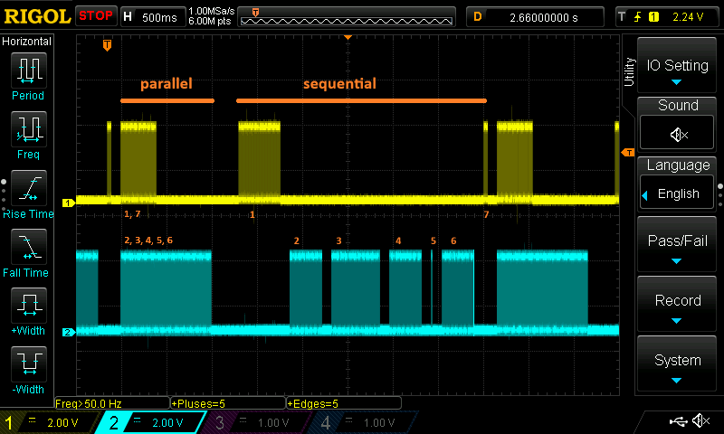
Demo: 7 commands in parallel
In the first demo, each motor picks up its own commands, and executes them right after each other. Motors run independently, at different speed.
The first motor will immediately execute the first and last command, and the second one immediately runs the middle 5.
The demo finishes when both motors have run the commands.
void full_demo(const commands_t & cmd) {
    // TODO: stepper driver IC should wake up here, if not yet
    // sleep_ms(1);

    // demo : run all in parallel
    run_commands(cmd, 7000, 4300);

    // ...

    // TODO: stepper driver IC can go back to sleep here
}

Demo: 7 commands in sequence
In the second demo, each command is sent after the previous one is completed.
There is not a lot that you need to different. Just send the commands from the batch one by one...
void full_demo(const commands_t & cmd) {
    // TODO: stepper driver IC should wake up here, if not yet
    // sleep_ms(1);

    // demo: run all in sequence
    for (auto &c: cmd) {
        std::array<motor_command,1> single_cmd {{c}};
        run_commands(single_cmd, 9000, 7000);
    }

    // ...


    // TODO: stepper driver IC can go back to sleep here
}
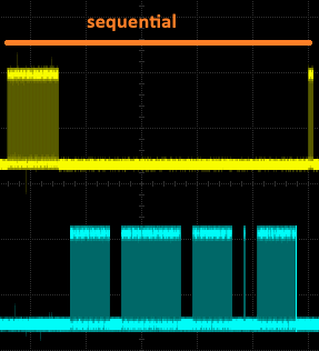
Both strategies can be intermixed. The gaps in the traces are for demo purposes, to have visual markers.
video: 1 PIO controls 4 stepper motors
What changes do you need to make for your design?
DIR and STEP pins: the two pins for each motor have to be next to each other. DIR is the first, and STEP has to be the next pin in the GPIO bank.
The example uses GPIO4 for motor 1 DIR, and GPIO6 for motor 2 DIR. And that implies that the STEP pins are GPIO5 and GPIO7.
To change this, alter these lines:
// TODO: adapt to your board designconst uint motor1_dir = 4U; // implies that step is gpio 5const uint motor2_dir = 6U; // implies that step is gpio 7
STEPPER DRIVER IC: the example doesn't contain stepper IC management. If you need to configure, enable or disable the IC during execution, add that logic.
There are placeholders in the code marked with:
// TODO: stepper driver IC <instructions>
I've created an example for
- Texas Instruments DRV8711: https://github.com/jancumps/pio_drv8711_stepper.
- Allegro A4988: https://github.com/jancumps/pio_a4988_stepper
Build instructions
A CMake file is available as a Gist, together with the example source.
Copy pico_sdk_import.cmake from the Picos C SDK root, or from their GitHub, to your project root.
Then build as you'd do with any Pico project.
The pio_stepper_lib is hosted on GitHub. You don't need to clone or build it, to use the library in your project. CMake does that for you.
The project with all necessary files: pico_stepper_2motors_20250421.zip. (includes .uf2 binary that you can drop on a Pico 1).
next post: Raspberry PIO stepper library documentation - 4: understand the step frequency

