


|
The Pico has a set of PIO co-processors. They are real-time controllers that can execute logic with deterministic timing. Ideal to run strict-timed sequences and state machines. And to implement extra peripherals.
|
Follow up of Stepper Motor Control with Raspberry Pico PIO and DRV8711 driver- Part 4: PIO .
The First 4 posts adapted Hackster project PIO Stepper Motor Control - an example that uses the Allegro A4988 stepper driver - to the DRV8711. It's a great example - almost the simplest PIO code you can find. It has limitations: it doesn't manage the DIR pin, and can do maximum 32 steps in a call.
In this new version, I deal with that. I wrote my own PIO program that can independently do up to 2147483647 steps. And the PIO handles the DIR pin. This means that you can really hand of a number of commands to the PIO FIFO input. And do something else in the meantime...
command structure
The data you send to the PIO is 32 bits.
- bit 0: direction. The DIR pin will be driven to the value you set in this LSB
- bit 31:1: steps. The PIO will send a pulse train to the STEP pin, with exactly the same pulses as requested
PIO code
.program stepper
.side_set 1
.define public DELAY 15
.wrap_target
start:
    pull block      side 0 ; Pull from FIFO to OSR
    out pins, 1     side 0 ; shift direction out of OSR and output to dir
    mov x, osr      side 0 ; Copy rest of OSR to scratch X
    jmp !x start    side 0
    jmp x-- count   side 0
count:
    ; nop             side 1 [DELAY] ; removed because we don't need a symmetrical pulse for a stepper
    jmp x-- count   side 0 [DELAY]
.wrap
What happens?
Preparation:
line 6 gets the data we passed in our main code (the command) into the output shift register. If no data provided, the state machine waits. It also keeps the step pin low.
on line 7, the DIR bit is shifted out of the shift register, sent to pin. This is the STEP pin of DRV8711. It still keeps the step pin low.
line 8 shifts the remaining 31 bits into scratch register x. This is our counter. It still keeps the step pin low.
line 9 aborts the run if we passed 0 steps. It still keeps the step pin low.
line 10 decreases the counter, and we move to the first pulse to generate. It still keeps the step pin low.
Then the loop:
line 12 finally sets the STEP pin high (rising edge of one pulse). It also delays until half the loop time, to keep frequency manageable
line 13 makes the process loop until the counter is exhausted. It also pulls the STEP pin down again (falling edge of that same pulse). It also delays for the remaining loop time, to keep frequency manageable
If the counter is exhausted, we created the requested amount of pulses, and we go back to line 10.
The delay that I use is the maximum I can get. Each instruction has 5 bits that are shared between delay and side step. Because I use 1 side step pin, I get 4 bits for delay. And that results in a maximum delay of 15.
PIO C helper
This is the setup code that's traditionally kept in the same .pio file. It sets up pins and configures which ones are driven as output, and which one as side step.
% c-sdk {
#include "hardware/clocks.h"
static inline void stepper_program_init(PIO pio, uint sm, uint offset, uint pin, float freq) {
   pio_gpio_init(pio, pin);
   pio_gpio_init(pio, pin+1);

   sm_config_set_out_pins(&c, pin, 2);
   pio_sm_set_consecutive_pindirs(pio, sm, pin, 2, true);
   pio_sm_config c = stepper_program_get_default_config(offset);
   sm_config_set_sideset_pins(&c, pin+1);

   float div = clock_get_hz(clk_sys) / (32*freq);
   sm_config_set_clkdiv(&c, div);

   pio_sm_init(pio, sm, offset, &c);
}
%}
The build process will generate a header file based on this info. This command in CMakeFiles.txt does that:
pico_generate_pio_header(${CMAKE_PROJECT_NAME} ${CMAKE_CURRENT_SOURCE_DIR}/source/stepper.pio)
The main program
First a few helper functions:
void init_pio() {
    // todo get free sm
    uint offset = pio_add_program(piostep, &stepper_program);
    printf("Loaded program at %d\n", offset);

    stepper_program_init(piostep, sm, offset, dir, frequency);
    pio_sm_set_enabled(piostep, sm, true);
}

void init_everything() {
    stdio_init_all();
    init_drv8711_gpio_hw();
    init_drv8711_spi_hw();
    init_drv8711_settings();
    init_pio();
}

inline uint32_t step_time(uint32_t steps) {
    return (steps > (UINT32_MAX >> 1)) ? 0 : steps * 1000 / frequency;
}

// Write `steps` to TX FIFO. State machine will copy this into X.
// max steps taken is 2147483647 (highest number that fits in 31 bits)
void pio_stepper_set_steps(PIO pio, uint sm, uint32_t steps, bool reverse) {
    if (steps > (UINT32_MAX >> 1)) {
        printf("%d is more than max steps (%d)\n", steps, UINT32_MAX >> 1);
        return;
    }
    pio_sm_put_blocking(pio, sm, steps << 1 | (reverse ? 0 : 1));
}
The two first ones are initialisation. Then a utility function that calculates how long it 'll take to make a number of steps.
The last function, pio_stepper_set_steps(), is the most interesting. That's the one that combines the number of steps and the direction bit.
If you pass a value that doesn'tt fit in 31 bits, the code does not pass the parameter to the PIO and prints a message.
If the step count is valid, it's shifted 1 bit to the left, and that bit then becomes the direction bit.
in main(), I just loop and keep sending between 0 and 255 steps to the PIO.
int main() {
    init_everything();

    uint32_t steps = 0U;
    {
        wakeup_drv8711 w;
        while (true) {
            printf("Steps = %d\n", steps);
            pio_stepper_set_steps(piostep, sm, steps, true);
            steps = (steps + 1) % 256;
            sleep_ms(10);
            // break;
        }
    }

    return 0;
}
If you want to learn about line 6, where the DRV8711 sleep mode is managed, check this side blog: embedded C++: manage a resource with a tiny* object .
With a little bit of extra code, you can create a program, feeding the PIO with commands.
struct command {
    uint32_t steps;
    bool reverse;
};

// ...
    std::array<command, 6> cmd{{{200, true}, {200, false},{200, false},{400, false},{250, true},{350, true}}};


    {
        wakeup_drv8711 w;
        for(auto c : cmd) {
            printf("Steps = %d\n", c.steps);
            pio_stepper_set_steps(piostep, sm, c.steps, c.reverse);
            // sleep the time it takes for the steps + 0.5 second
            // for demo purpose
            sleep_ms(step_time(c.steps) + 500);
        }
        sleep_ms(500); // give enough time to complete the action
    }
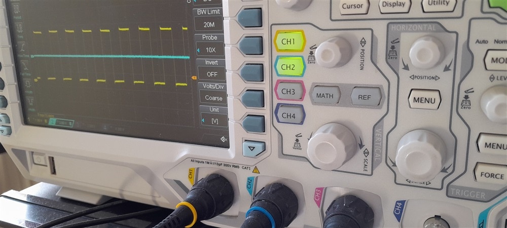
Here's how this looks like on a scope. Blue is the direction pin.
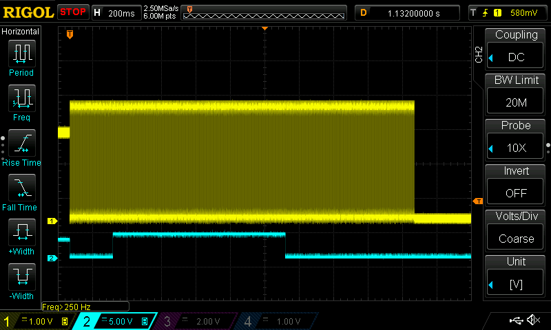
The video near the start of this blog shows the same sequence, but I added a little pause between the steps for visibility.
Thank you for reading. Next post: Stepper Motor Control with Raspberry Pico PIO and DRV8711 driver- Part 6: autonomous PIO with speed control
GitHub drv8711 project repository.
GitHub PIO stepper lib repository.
Here's the project code: pio_drv8711_stepper_20250406.zip
Top Comments