element14 Community
element14 Community
    Register Log In
  • Site
  • Search
  • Log In Register
  • Community Hub
    Community Hub
    • What's New on element14
    • Feedback and Support
    • Benefits of Membership
    • Personal Blogs
    • Members Area
    • Achievement Levels
  • Learn
    Learn
    • Ask an Expert
    • eBooks
    • element14 presents
    • Learning Center
    • Tech Spotlight
    • STEM Academy
    • Webinars, Training and Events
    • Learning Groups
  • Technologies
    Technologies
    • 3D Printing
    • FPGA
    • Industrial Automation
    • Internet of Things
    • Power & Energy
    • Sensors
    • Technology Groups
  • Challenges & Projects
    Challenges & Projects
    • Design Challenges
    • element14 presents Projects
    • Project14
    • Arduino Projects
    • Raspberry Pi Projects
    • Project Groups
  • Products
    Products
    • Arduino
    • Avnet & Tria Boards Community
    • Dev Tools
    • Manufacturers
    • Multicomp Pro
    • Product Groups
    • Raspberry Pi
    • RoadTests & Reviews
  • About Us
  • Store
    Store
    • Visit Your Store
    • Choose another store...
      • Europe
      •  Austria (German)
      •  Belgium (Dutch, French)
      •  Bulgaria (Bulgarian)
      •  Czech Republic (Czech)
      •  Denmark (Danish)
      •  Estonia (Estonian)
      •  Finland (Finnish)
      •  France (French)
      •  Germany (German)
      •  Hungary (Hungarian)
      •  Ireland
      •  Israel
      •  Italy (Italian)
      •  Latvia (Latvian)
      •  
      •  Lithuania (Lithuanian)
      •  Netherlands (Dutch)
      •  Norway (Norwegian)
      •  Poland (Polish)
      •  Portugal (Portuguese)
      •  Romania (Romanian)
      •  Russia (Russian)
      •  Slovakia (Slovak)
      •  Slovenia (Slovenian)
      •  Spain (Spanish)
      •  Sweden (Swedish)
      •  Switzerland(German, French)
      •  Turkey (Turkish)
      •  United Kingdom
      • Asia Pacific
      •  Australia
      •  China
      •  Hong Kong
      •  India
      •  Korea (Korean)
      •  Malaysia
      •  New Zealand
      •  Philippines
      •  Singapore
      •  Taiwan
      •  Thailand (Thai)
      • Americas
      •  Brazil (Portuguese)
      •  Canada
      •  Mexico (Spanish)
      •  United States
      Can't find the country/region you're looking for? Visit our export site or find a local distributor.
  • Translate
  • Profile
  • Settings
RoadTests & Reviews
  • Products
  • More
RoadTests & Reviews
RoadTest Forum UPDATE on Seeking Ideas for RoadTesting Antennas
  • Blogs
  • RoadTest Forum
  • Documents
  • RoadTests
  • Reviews
  • Polls
  • Files
  • Members
  • Mentions
  • Sub-Groups
  • Tags
  • More
  • Cancel
  • New
Join RoadTests & Reviews to participate - click to join for free!
Actions
  • Share
  • More
  • Cancel
Forum Thread Details
  • Replies 21 replies
  • Subscribers 2564 subscribers
  • Views 2667 views
  • Users 0 members are here
  • scasny
Related

UPDATE on Seeking Ideas for RoadTesting Antennas

rscasny
rscasny over 7 years ago

I finally got some information on the antennas that I want to roadtest. These antennas are for Frequency / application :  2.4/5GHz Antenna – typical for Bluetooth, WiFi.


Here they are:


image


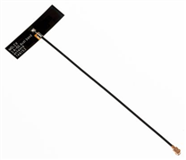
2.4GHz / 5GHz Wi-Fi Stand Alone Balance Antenna with MHF Connector, 9.00mm Width, Cable Length 100.00mm

  • Product Name: 2.4/5GHz Balanced Flex Antenna
  • Protocol: BLE, BT, Thread, Wi-Fi, Wireless Hart, Zigbee
  • Type: Wi-Fi Antenna
  • Cable Length: 100.00mm
  • Length: 34.90mm
  • Mounting Style Adhesive
  • Net Weight: 0.574/g
  • Packaging Type: PET Film
  • Polarization: Linear
  • Radiation Pattern: Omnidirectional
  • Thickness: 0.10mm
  • Width: 9.00mm

Click Here for More information


image


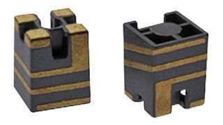
2.4GHz SMT On-ground MID Chip Antenna

  • Product Name: 2.4GHz SMT OnGround MID Chip
  • Protocol: BLE, BT, Thread, Wi-Fi, Wireless Hart, Zigbee
  • Type: Wi-Fi Antenna
  • Length: 3.00mm
  • Mounting Style: Surface Mount
  • Net Weight: 0.042/g
  • Polarization: Linear
  • Radiation Pattern: Omnidirectional
  • Thickness: 4.00mm
  • Width: 3.00mm

Click Here for More Information


Your thoughts about roadtesting these specific products would be appreciated. Thanks.


Sincerely,


Randall Scasny

RoadTest Program Manager

  • Sign in to reply
  • Cancel

Top Replies

  • jadew
    jadew over 7 years ago +9
    This is going to be difficult to roadtest. Normally, when you design a product, and it's the first time you evaluate antennas for it, you select a couple of antennas that fit the specifications and try…
  • DAB
    DAB over 7 years ago +8
    I worked on many RF projects, including building an integrated test facility for testing all antennas on aircraft in a huge anechoic facility, so I am not sure what you would have anyone do with just the…
  • awneil
    awneil over 7 years ago in reply to mcb1 +7
    mcb1 wrote: To test these you need a transmitter with adjustable gain, and a receiver that can provide the RSSI (Received signal strength). They need to be tested in an open environment, clear from reflections…
  • kas.lewis
    kas.lewis over 7 years ago

    This definitely sounds interesting, for those without the "right" gear, one idea would be to use something like SmartRF from TI that allows for some of these variables to be altered and monitored. Then by measuring something like RSSI or BER depending on positioning of the units some inference of antenna pattern or gain gould be made. All this being said, you would still need a consistent preferably quite environment... anyone up for a drive to the country ??


    The same could be done using a spectrum analyzer in a quiet environment to get an idea of antenna pattern. Alternatively the road test could include a decent amount of RF absorbing foam for the roadtester to build their own chamber.... they could then report back on how easy/hard this was and how well or not it worked out. image


    Kas

    • Cancel
    • Vote Up 0 Vote Down
    • Sign in to reply
    • Cancel
  • DiligentMinds.com
    DiligentMinds.com over 7 years ago

    There is a lot of interesting testing that can be done with the FPC1000 I already have-- but I don't know how useful it would be.  These antennas are going to be affected by how they are mounted and what they are mounted on.  Perhaps that could be part of the test, but that would mean that the road-tester would probably need multiple examples of each antenna that could be mounted in different ways (as well as an unmounted one)-- so that we can see an example of how they are effected by their near-field environment.


    The surface mount version would need some kind of example PC board to test with (no doubt the manufacturer already has this).  Without an FPC1500 (or other 2-port VNA), these could be supplied with some simplified test devices-- maybe some WiFi radios and also a simple antenna noise bridge.


    The antenna patterns could be recorded in a remote spot in an "RF dead zone" (we have lot's of this in the desert)--  One would only need a way to record the relative signal level, while rotating the antenna-- a WiFi receiver that can supply the RSSI signal, a spectrum analyzer, or RF signal strength meter (etc), along with a signal source for a reference antenna placed a suitable distance away.


    Sounds like a fun project!

    • Cancel
    • Vote Up +1 Vote Down
    • Sign in to reply
    • Cancel
  • genebren
    genebren over 7 years ago

    A lot of people will argue that the only way to test an antenna would be with very expensive instrumentation and in an electronically clean environment.  While testing antennas is not my occupation or even something that I do often (more likely never), there are some simple ways to test them.  Way back in the dark ages, when AM and FM broadcasting was viewed as the highest frequencies that people would deal with, a radio station would need to test their signal patterns, by driving around and measuring signal strength using a tuned voltmeter.  These days, the same can be done, but simply by using the RSI (Relative Strength Index) values available within most receivers.  While working on a Zigbee meshed system, our clever RF engineer, would set up a meshed system in an unobstructed warehouse, with nodes populated through out the building.  He could then test a node, by broadcasting messages and collecting RSI values from nodes within the building (the messages needed to be qualified, so that re-transmitted, or bounced signals would be ignored) and build a signal strength profile map.  We mostly used this test to determine if our node placed inside of a fixture was overly attenuated due to all the surrounding materials.


    A modification of this method could prove to be helpful in testing antennas by mapping out RSI values gathered from different locations around a transmitter/antenna pair.


    Just a thought.

    Gene

    • Cancel
    • Vote Up +3 Vote Down
    • Sign in to reply
    • Cancel
  • shabaz
    shabaz over 7 years ago in reply to genebren

    I agree, plus there are a load of things that are subjective but still highly useful to know, such as how well built the antennas are, if any hinge parts seem reliable (I've seen failed antennas from new, because of manufacturing tolerances in the hinge contact), and does the antenna cause rotation of the center pin when fitting it (e.g. some may prefer antennas where the center pin is not rotated when installing the antenna).

    It is unrealistic to expect the antenna to be subjected to a full suite of measurements as (say) a consultant would do, because such tasks are normally chargeable at tens of thousands of $$. Besides, for a real deployment such antenna matching would be done with the antenna mounted to the product.


    As you say, there are plenty of practical things anyone can do. As another example, when soldiers 'create' an antenna by slinging wire over a tree, they make the best of what they can to determine antenna quality, using relatively simple procedures at their disposal since they are in the field. That's at far lower frequencies than (say) WLAN and Bluetooth of course, but still, measuring signal strength by moving around an area is a practical method for these higher frequencies like you mention.


    Basically often I'm interested to hear the practical stuff like usability, some of the subjective stuff as mentioned above too, and how particular aspects of a product could benefit an application, and if it functions well for certain roles, rather than a quantified verification of the manufacturer's datasheet.

    • Cancel
    • Vote Up +2 Vote Down
    • Sign in to reply
    • Cancel
  • mcb1
    mcb1 over 7 years ago in reply to genebren

    Way back in the dark ages, when AM and FM broadcasting was viewed as the highest frequencies that people would deal with, a radio station would need to test their signal patterns, by driving around and measuring signal strength

    Hey less of the dark ages stuff there sonny. image


    When I worked for Telecom (it seems way back now) that was how we proved our coverage areas.

    We had a number of existing sites, and the appropriate antenna and transmitter would be installed, and then we'd hop in a car and drive all around the Canterbury plains to prove the coverage area was acceptable.


    It was interesting when we ventured into UHF, as it behaved very well in the city and even a remote town (148km away) with tall buildings yielded a surprising result.

    This was of course at odds with VHF that is basically a line of sight service, although the path was half water and half open plain.


    Mark

    • Cancel
    • Vote Up +3 Vote Down
    • Sign in to reply
    • Cancel
  • rscasny
    rscasny over 7 years ago

    I want to thank everyone who has contributed their ideas about an antenna roadtest.


    I met with the supplier again, so this roadtest is coming closer to a reality.


    The supplier is planning on giving me "developer kits" that include the antenna and some kind of dev board for tx/rec.


    They also are interested in the PCb mounted antenna. Apparently, it has gotten a lot of designers who had problems placing the antenna on the pcb. Depending where it is placed can impact the antenna.


    Another problem they are experiencing are obstacles (coverage/penetration losses).


    The final problem they are experiencing is (as expected) plain old improper installation problems.


    I'll keep you posted. Thanks, again.


    Randall Scasny

    RoadTest Program Manager

    • Cancel
    • Vote Up +6 Vote Down
    • Sign in to reply
    • Cancel
  • Former Member
    Former Member over 7 years ago

    The omnidirectional one has many practical uses. Too much for one post, but the materials can be as basic any AP. I am interested in working with the http://www.farnell.com/datasheets/2574507.pdf?_ga=2.204827353.892327570.1527912145-949474904.1527912145 .

    • Cancel
    • Vote Up 0 Vote Down
    • Sign in to reply
    • Cancel
  • station240
    station240 over 7 years ago in reply to rscasny

    Ah if it includes an RX/TX board I might be interested.

    Could be a nice little test to map signal coverage inside a house.

    • Cancel
    • Vote Up 0 Vote Down
    • Sign in to reply
    • Cancel
  • Fred27
    Fred27 over 7 years ago

    Antenna testing is indeed a tricky and complicated business. It's hard to know what a road test can add to the manufacturer's datasheet. I considered buying TI's CC-ANTENNA-DK2 recently to help creating a custom CC1310 based PCB. I decided there would be little benefit over reading the corresponding documentation and going with the recommended design that would fit.

    • Cancel
    • Vote Up 0 Vote Down
    • Sign in to reply
    • Cancel
  • shabaz
    shabaz over 7 years ago

    Hi Randall,


    I'd be happy to try out both antennas for a practical type of RoadTest with Bluetooth LE, since I'm already working on a PCB here:

    Smart Doorbell System – Part 5 – Final Bell Push Circuit and Antenna Design


    For the chip antenna, I'll need to create a different revision of the PCB, but it would be just a small change (i.e. remove the Inverted F antenna and have the pads for the chip antenna instead). I might need to have (say) e-mail contact with a Molex technical person to do it properly, although the information on their website is pretty good.


    Thanks,


    Shabaz.

    • Cancel
    • Vote Up +3 Vote Down
    • Sign in to reply
    • Cancel
<>
element14 Community

element14 is the first online community specifically for engineers. Connect with your peers and get expert answers to your questions.

  • Members
  • Learn
  • Technologies
  • Challenges & Projects
  • Products
  • Store
  • About Us
  • Feedback & Support
  • FAQs
  • Terms of Use
  • Privacy Policy
  • Legal and Copyright Notices
  • Sitemap
  • Cookies

An Avnet Company © 2025 Premier Farnell Limited. All Rights Reserved.

Premier Farnell Ltd, registered in England and Wales (no 00876412), registered office: Farnell House, Forge Lane, Leeds LS12 2NE.

ICP 备案号 10220084.

Follow element14

  • X
  • Facebook
  • linkedin
  • YouTube