element14 Community
element14 Community
    Register Log In
  • Site
  • Search
  • Log In Register
  • Community Hub
    Community Hub
    • What's New on element14
    • Feedback and Support
    • Benefits of Membership
    • Personal Blogs
    • Members Area
    • Achievement Levels
  • Learn
    Learn
    • Ask an Expert
    • eBooks
    • element14 presents
    • Learning Center
    • Tech Spotlight
    • STEM Academy
    • Webinars, Training and Events
    • Learning Groups
  • Technologies
    Technologies
    • 3D Printing
    • FPGA
    • Industrial Automation
    • Internet of Things
    • Power & Energy
    • Sensors
    • Technology Groups
  • Challenges & Projects
    Challenges & Projects
    • Design Challenges
    • element14 presents Projects
    • Project14
    • Arduino Projects
    • Raspberry Pi Projects
    • Project Groups
  • Products
    Products
    • Arduino
    • Avnet Boards Community
    • Dev Tools
    • Manufacturers
    • Multicomp Pro
    • Product Groups
    • Raspberry Pi
    • RoadTests & Reviews
  • About Us
  • Store
    Store
    • Visit Your Store
    • Choose another store...
      • Europe
      •  Austria (German)
      •  Belgium (Dutch, French)
      •  Bulgaria (Bulgarian)
      •  Czech Republic (Czech)
      •  Denmark (Danish)
      •  Estonia (Estonian)
      •  Finland (Finnish)
      •  France (French)
      •  Germany (German)
      •  Hungary (Hungarian)
      •  Ireland
      •  Israel
      •  Italy (Italian)
      •  Latvia (Latvian)
      •  
      •  Lithuania (Lithuanian)
      •  Netherlands (Dutch)
      •  Norway (Norwegian)
      •  Poland (Polish)
      •  Portugal (Portuguese)
      •  Romania (Romanian)
      •  Russia (Russian)
      •  Slovakia (Slovak)
      •  Slovenia (Slovenian)
      •  Spain (Spanish)
      •  Sweden (Swedish)
      •  Switzerland(German, French)
      •  Turkey (Turkish)
      •  United Kingdom
      • Asia Pacific
      •  Australia
      •  China
      •  Hong Kong
      •  India
      •  Korea (Korean)
      •  Malaysia
      •  New Zealand
      •  Philippines
      •  Singapore
      •  Taiwan
      •  Thailand (Thai)
      • Americas
      •  Brazil (Portuguese)
      •  Canada
      •  Mexico (Spanish)
      •  United States
      Can't find the country/region you're looking for? Visit our export site or find a local distributor.
  • Translate
  • Profile
  • Settings
Embedded and Microcontrollers
  • Technologies
  • More
Embedded and Microcontrollers
Blog EasyL1105 MSPM0 board: hello, world
  • Blog
  • Forum
  • Documents
  • Quiz
  • Polls
  • Files
  • Members
  • Mentions
  • Sub-Groups
  • Tags
  • More
  • Cancel
  • New
Join Embedded and Microcontrollers to participate - click to join for free!
  • Share
  • More
  • Cancel
Group Actions
  • Group RSS
  • More
  • Cancel
Engagement
  • Author Author: Jan Cumps
  • Date Created: 9 Sep 2025 7:16 PM Date Created
  • Views 463 views
  • Likes 7 likes
  • Comments 16 comments
  • MSPM0L1105
  • MSPM0
  • easyL1105
  • texas instruments
  • ti
Related
Recommended

EasyL1105 MSPM0 board: hello, world

Jan Cumps
Jan Cumps
9 Sep 2025
EasyL1105 MSPM0 board: hello, world

 shabaz designed a development kit for the recent Texas Instruments MSPM0 microcontroller series. 
In this post, a little hello, world example. Complexity: low.

image
(post that introduces the kit)

Required hardware and software

  • EasyL1105 kit
  • USB cable to connect EasyL1105 kit to PC
  • a serial monitor (PuTTY, ...)
  • handy: an XDS110 debugger, and an IDE that supports that. I use ccstudio 20 (it also has a built-in serial monitor)

Functionality

This program sends hello, world to the MSPM0 UART0. If you put the UART jumpers on the board, the data will arrive on your PC. Like most SDK examples, I use 9600 baud, 8, N 1.

Start an empty project

In ccstudio, you create a new one based on the MSPM0L1105 empty example. Steps are explained here:  Use TI Code Composer Studio with EasyL1105 MSPM0 board . Also follow the steps there, to select the 28 pin version of the controller.

Before making any changes, build the project. This should complete successful.

If you use GCC and bootloader, start from shabaz ' example, and use make, GCC and standalone SysConfig to make the changes and build the firmware, 

SysConfig

The only configuration that's required, is the UART:

image

image

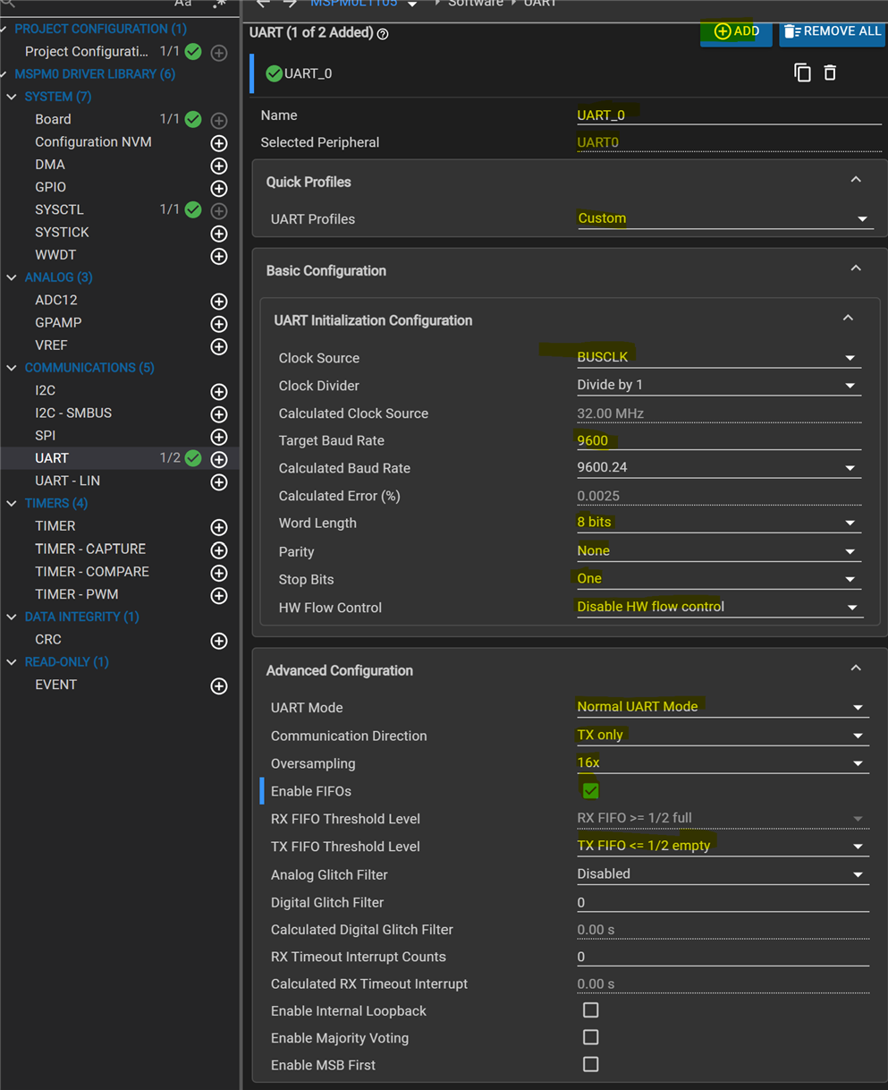
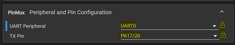
In essence: UART0, transmission only, to PA17.

Code

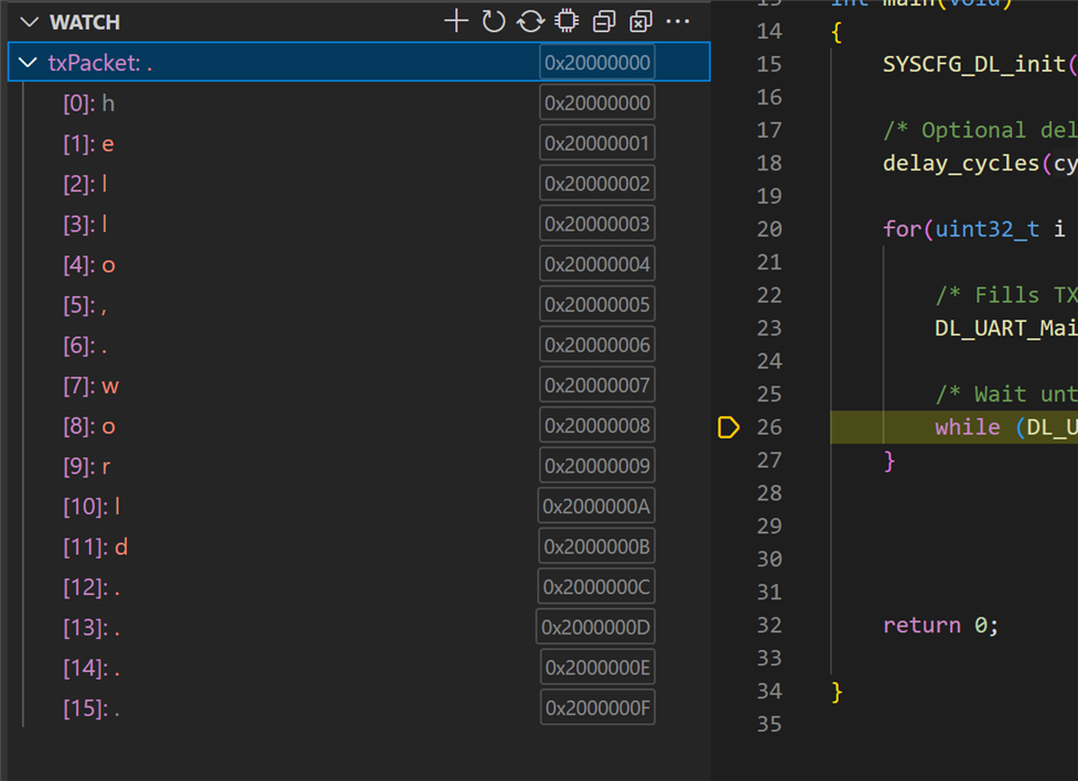
MSPM0 has 4 bytes FIFO. The string that I'm sending is 16 bytes. I let the program loop 4 times over the string, snooping a full FIFO. I wait for the next batch until the buffer is free.

#include "ti_msp_dl_config.h"

/* Delay for 5ms to ensure UART TX is idle before starting transmission */
#define UART_TX_DELAY (160000)


#define buf_len 16
#define fifo_len 4

/* Data for UART to transmit */
uint8_t txPacket[buf_len] = {"hello, world  \r\n"};

int main(void)
{
    SYSCFG_DL_init();

    /* Optional delay to ensure UART TX is idle before starting transmission */
    delay_cycles(UART_TX_DELAY);

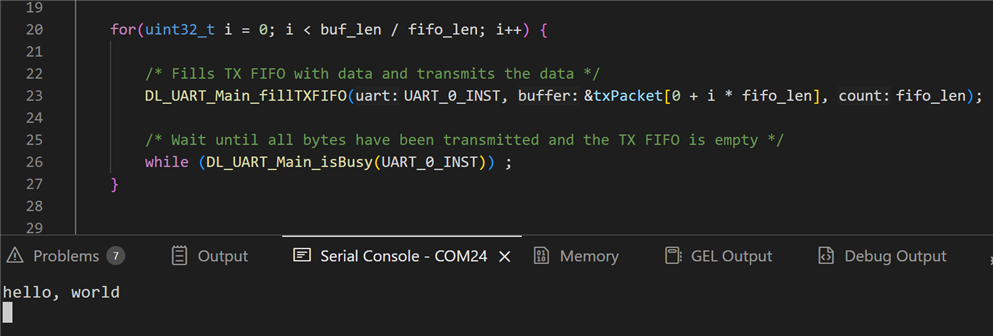
    for(uint32_t i = 0; i < buf_len / fifo_len; i++) {

        /* Fills TX FIFO with data and transmits the data */
        DL_UART_Main_fillTXFIFO(UART_0_INST, &txPacket[0 + i * fifo_len], fifo_len);

        /* Wait until all bytes have been transmitted and the TX FIFO is empty */
        while (DL_UART_Main_isBusy(UART_0_INST)) ;
    }


    return 0;

}

Program and Test with ccstudio and XDS110

  • Connect an XDS110 debugger as explained here:  Cheap debugger ($6) for EasyL1105 MSPM0 board .
  • Remove all headers from the EasyL1105 - including the power ones. The debugger will power the board.
  • connect your terminal program to the debugger COM
  • start the program. It 'll show hello, world on the terminal

image

Program and Test with GCC and bootloader

  • mount only the power and BSL jumpers on the EasyL1105
  • connect the EasyL1105 USB to your PC
  • follow shabaz ' instructions to build the program and load the firmware over USB on the board:   EasyL1105: A Dev Board for the TI ARM Cortex-M0+ L-Series 
  • disconnect the board, remove BSL jumpers and place only the UART0_TX one. Plug back in.
  • connect your terminal program to the EasyL1105 COM
  • reset the EasyL1105. It 'll show hello, world on the terminal

Thank you for reading.

CCS project used in this post: EasyL1105_helloworld_20250909.zip

Related posts

  • Sign in to reply
  • shabaz
    shabaz 1 month ago in reply to Jan Cumps

    It would possibly be very good at showing how to decode it (e.g. what image processing steps to take) more than performing the decode from the image itself. For instance, any techniques to get rid of the noise, or to figure out the edges, and then somehow work out where to sample the bits. 

    I tried getting it to create a world map the other day (programmatically from Python code). The aim was to deliberately encode heights (and depths) in the colours, so I didn't want to use any random online map. This one needed about 11 Gbytes of map data downloads (I don't know anything about this, but let ChatGPT figure that out, and I mostly just messed with the Python code snippets it generated, told it I wanted borders, etc).

    image

    • Cancel
    • Vote Up 0 Vote Down
    • Sign in to reply
    • More
    • Cancel
  • Jan Cumps
    Jan Cumps 1 month ago in reply to shabaz

    It guessed that the data was in the magenta. But t originally tried to convert it into a graph with the amount of magenta per time. And derive payload from that. 
    It never got anywhere, also not when I gave the outcome. It tried franticly though Slight smile.

    • Cancel
    • Vote Up 0 Vote Down
    • Sign in to reply
    • More
    • Cancel
  • shabaz
    shabaz 1 month ago in reply to Jan Cumps

    Hehe possibly it could do it a different way, perhaps write some code to convert from a supplied cropped image, to convert that purple stream into values for feeding into a logic analyzer. I tried to make it do the reverse (easier), to show what 'hello' should look like. It was not bad, the result was correct as far as I can tell, although it struggled with making the text look readable, since it was squashed up:

    https://chatgpt.com/share/68c57f62-6b70-8004-bead-7c14772e6f3e

    image

    • Cancel
    • Vote Up 0 Vote Down
    • Sign in to reply
    • More
    • Cancel
  • beacon_dave
    beacon_dave 1 month ago in reply to Jan Cumps

    So basically you did all the work and ChatGPT came along and took the credit ? Joy

    • Cancel
    • Vote Up 0 Vote Down
    • Sign in to reply
    • More
    • Cancel
  • Jan Cumps
    Jan Cumps 1 month ago in reply to beacon_dave

    I tried ChatGPT. First I used the above trace, without the green decode. I informed it was UART, 115200. It didn't get it.
    Then I told it was "hello". GPT couldn't trace it back to "hello"

    Then uploaded the image with the scope decode, and it worked Slight smile

    image

    • Cancel
    • Vote Up 0 Vote Down
    • Sign in to reply
    • More
    • Cancel
>
element14 Community

element14 is the first online community specifically for engineers. Connect with your peers and get expert answers to your questions.

  • Members
  • Learn
  • Technologies
  • Challenges & Projects
  • Products
  • Store
  • About Us
  • Feedback & Support
  • FAQs
  • Terms of Use
  • Privacy Policy
  • Legal and Copyright Notices
  • Sitemap
  • Cookies

An Avnet Company © 2025 Premier Farnell Limited. All Rights Reserved.

Premier Farnell Ltd, registered in England and Wales (no 00876412), registered office: Farnell House, Forge Lane, Leeds LS12 2NE.

ICP 备案号 10220084.

Follow element14

  • X
  • Facebook
  • linkedin
  • YouTube