


|
PID controller implementation without using integer arithmetic. Uses TI IQMath lib to replace floating point instructions.
|

Some of the content is created with AI support. I've marked the parts where AI was used.
All narrative is written by me.
Math and PID
Traditionally, the PID algorithm uses floating point math. For an MSPM0 controller, those are expensive runtime calculations. And they have to be done in each execution of the PID control loop.
TI MSPM0 SDK comes with the IQMath library. A library that lets you represent floating point numbers in an integer variable. And lets you calculate with them. I implemented the PID algorithm using IQMath variables and algorithms.
The lib is used to:
- declare floating point values to IQMath representation
- multiply IQMath variables
It's not used to add values. You can just the C traditional + operation on IQMath variables.
I also didn't use the lib to convert ADC (the PID feedback signal) and PWM (the PWM output signal) to IQMath. Because of their nature, there was an optimised way to convert those.
The lib allows you to select the number of bits reserved for the fractional part. I used the default Q(24) format, where 24 bits of an int32_t are used for fractional.
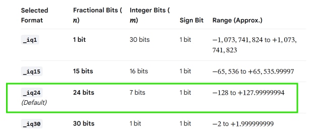
source: Google's Gemini AI
PID algorithm
I created a C++ class that implements the PID algorithm, and can hold the controller state..
#include <ti/iqmath/include/IQmathLib.h>

const _iq out_max = _IQ(1.0);        // Maximum allowable output (e.g., _IQ(1.0) for 100% PWM)
const _iq out_min = _IQ(0.0);        // Minimum allowable output (e.g., _IQ(0.0) for 0% PWM)


class pid {
    public:
    pid(_iq kp, _iq ki, _iq kd) : kp(kp), ki(ki), kd(kd) {}

    void init(_iq kp, _iq ki, _iq kd, bool reset = true) {
        kp = kp;
        ki = ki;
        kd = kd;

        if (reset) {
            reset_state();
        }
    }

    _iq compute(_iq setpoint, _iq feedback) {
        _iq error;
        _iq p_term, i_term, d_term;
        _iq output;

        // 1. Calculate the current error (e = r - y)
        error = setpoint - feedback;

        // 2. Proportional Term: P = kp * error
        p_term = _IQmpy(kp, error);

        // 3. Integral Term with anti-windup: I = I_prev + (ki * error)
        integral = integral + _IQmpy(ki, error);

        // Anti-windup: Clamp the integral accumulator to prevent runway saturation
        if (integral > out_max) {
            integral = out_max;
        } else if (integral < out_min) {
            integral = out_min;
        }

        i_term = integral;

        // 4. Derivative Term: D = kd * (error - prev_error)
        d_term = _IQmpy(kd, error - previous_error);

        // 5. Total Output: Control = P + I + D
        output = p_term + i_term + d_term;

        // 6. Save current error for the next execution cycle's derivative calculation
        previous_error = error;

        // 7. Final Output Saturation: Clamp the overall control signal
        if (output > out_max) {
            output = out_max;
        } else if (output < out_min) {
            output = out_min;
        }

        return output;
    }

private:
    _iq kp;
    _iq ki;
    _iq kd;
    _iq integral = _IQ(0.0);
    _iq previous_error = _IQ(0.0);

    inline void reset_state() {
        integral = _IQ(0.0);
        previous_error = _IQ(0.0);
    }
};
I used Google Gemini AI to suggest algorithm transition from floating point to IQMath Q(24). I reviewed and adapted where needed, and turned it into a class.
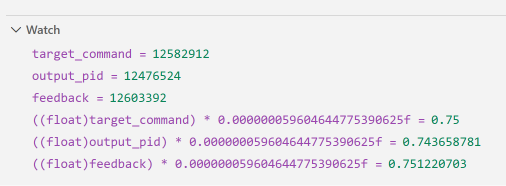
Highlights of the class:
- at initialisation, you set the PID Kp, Ki and Kd parameters. They are all in Q(24) format.
- they can be tweaked at runtime with the init() method
- the compute() method implements the algoritm using integer math only, no floating point.
- runtime state is kept in two Q(24) data members: integral and previous_error.
Use Case
I reused my project PID temperature controller for the EasyL1105 MSPM0 board - Pt. 1: framework . And replaced the PID algorithm with this class.
The project tries to set an output voltage to a given set level.. It uses PWM to generate that voltage. ADC is used to measure that voltage.
At runtime, the PID algorithm constantly validates if the voltage matches the set level. If not, ith adjusts the PWM duty cycle to drive the voltage either up or down.
PID controller object creation:
pid controller(_IQ(0.1), _IQ(0.01), _IQ(0.05)); // Example PID gains for voltage control
Set the desired output (value between 0 and 1):
_iq target_command = _IQ(0.75);
The control loop:
    while (1) {
        if (perform) {
            perform = false;

            perform_adc();

            perform_pid();

            perform_pwm();

        }
    }
perform_adc() retrieves the current output, and translates it to a Q(24):
void perform_adc() {
    DL_ADC12_startConversion(ADC12_0_INST);
    while (false == checkADC) {
        __WFE();
    }

    // Shift left by 12 bits (24 minus 12 equals 12)

    feedback = _iq(DL_ADC12_getMemResult(ADC12_0_INST, DL_ADC12_MEM_IDX_0)) << 12; // Direct to 0.0 - 1.0 per-unit in Q24!

    checkADC = false;
    DL_ADC12_enableConversions(ADC12_0_INST);
}
You can spot that I use an optimised shift to translate the 12-bits ADC to a Q(24).
I used Google Gemini AI to suggest the most performant way to translate the 12 bits to Q(24)
performe_pid() calls the algorithm:
void perform_pid() {
    output_pid = controller.compute(target_command, feedback);
}
The PID takes the desired voltage, and the value the ADC reported. It then calculates the PMW duty cycle that 'll get us there.
perform_pwm() then alters the duty cycla, as suggested by the algorythm:
void perform_pwm() {

    // Convert Q24 per-unit (0.0 to 1.0) to raw timer counts (0 to 65536)
    int32_t pwm_counts = output_pid >> 8;

    DL_TimerG_setCaptureCompareValue(PWM_0_INST, pwm_counts,
        DL_TIMER_CC_0_INDEX); // update ccr0 value

}
Again, a shift was used to translate the Q(24) to the desired duty cycle value for PWM register.
I used Google Gemini AI to suggest the most performant way to translate the Q(24) to DL_TIMER_CC_0_INDEX
Result
This "measure - assess - correct" loop is driven by a common timer, that makes it run every 200 ms.
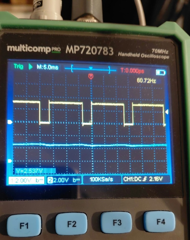
You can influence speed and stability by tuning the 3 parameters.
AI can support. You can ask it to suggest parameters to make it move faster to the set point, to react faster or slower on load changes, to improve stability, to avoid ringing or overshoot...
This is how Google Gemini AI explains the role of the parameters: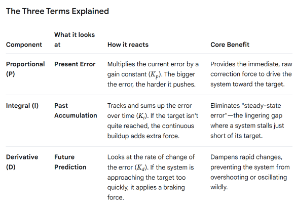
Resources used:
- ADC0, with input pin PA25. Its interrupt flags when conversion done
- PWM timer TIMG1, with output pin PA26
- generic timer PWMG0, to make the control loop tick every 200 ms. It fires an Interrupt to signal the loop has to be executed.
- GPIO pin PA27 to make a LED light up when the loop runs.
The loop is so fast that you can't see it, but you can put an oscilloscope over it.
The attached project targets the MSPM0L1306 Launchpad. But you can adapt it to EasyL1105 with SysConfig.
references:
- TI IQMath library. It's part of the MSPM0 SDK.
- MSPM0 IQMath example.
- PID controller on Wikipedia
- EasyL1105 development board.
- Expressif also uses that IQMath library.
Thank you for reading.
VS Code project: mspm0_pid_20261012.zip
(check this post for the expected VS Code workspace settings: MSPM0 project with VS Code, CMake and GCC - part 6: empty "template" project )
part of the EasyL1105 series. all posts
