element14 Community
element14 Community
    Register Log In
  • Site
  • Search
  • Log In Register
  • Community Hub
    Community Hub
    • What's New on element14
    • Feedback and Support
    • Benefits of Membership
    • Personal Blogs
    • Members Area
    • Achievement Levels
  • Learn
    Learn
    • Ask an Expert
    • eBooks
    • element14 presents
    • Learning Center
    • Tech Spotlight
    • STEM Academy
    • Webinars, Training and Events
    • Learning Groups
  • Technologies
    Technologies
    • 3D Printing
    • FPGA
    • Industrial Automation
    • Internet of Things
    • Power & Energy
    • Sensors
    • Technology Groups
  • Challenges & Projects
    Challenges & Projects
    • Design Challenges
    • element14 presents Projects
    • Project14
    • Arduino Projects
    • Raspberry Pi Projects
    • Project Groups
  • Products
    Products
    • Arduino
    • Avnet Boards Community
    • Dev Tools
    • Manufacturers
    • Multicomp Pro
    • Product Groups
    • Raspberry Pi
    • RoadTests & Reviews
  • About Us
  • Store
    Store
    • Visit Your Store
    • Choose another store...
      • Europe
      •  Austria (German)
      •  Belgium (Dutch, French)
      •  Bulgaria (Bulgarian)
      •  Czech Republic (Czech)
      •  Denmark (Danish)
      •  Estonia (Estonian)
      •  Finland (Finnish)
      •  France (French)
      •  Germany (German)
      •  Hungary (Hungarian)
      •  Ireland
      •  Israel
      •  Italy (Italian)
      •  Latvia (Latvian)
      •  
      •  Lithuania (Lithuanian)
      •  Netherlands (Dutch)
      •  Norway (Norwegian)
      •  Poland (Polish)
      •  Portugal (Portuguese)
      •  Romania (Romanian)
      •  Russia (Russian)
      •  Slovakia (Slovak)
      •  Slovenia (Slovenian)
      •  Spain (Spanish)
      •  Sweden (Swedish)
      •  Switzerland(German, French)
      •  Turkey (Turkish)
      •  United Kingdom
      • Asia Pacific
      •  Australia
      •  China
      •  Hong Kong
      •  India
      •  Korea (Korean)
      •  Malaysia
      •  New Zealand
      •  Philippines
      •  Singapore
      •  Taiwan
      •  Thailand (Thai)
      • Americas
      •  Brazil (Portuguese)
      •  Canada
      •  Mexico (Spanish)
      •  United States
      Can't find the country/region you're looking for? Visit our export site or find a local distributor.
  • Translate
  • Profile
  • Settings
Embedded and Microcontrollers
  • Technologies
  • More
Embedded and Microcontrollers
Blog PID temperature controller for the EasyL1105 MSPM0 board - Pt. 3: PWM
  • Blog
  • Forum
  • Documents
  • Quiz
  • Polls
  • Files
  • Members
  • Mentions
  • Sub-Groups
  • Tags
  • More
  • Cancel
  • New
Join Embedded and Microcontrollers to participate - click to join for free!
  • Share
  • More
  • Cancel
Group Actions
  • Group RSS
  • More
  • Cancel
Engagement
  • Author Author: Jan Cumps
  • Date Created: 2 Oct 2025 6:27 PM Date Created
  • Views 424 views
  • Likes 5 likes
  • Comments 25 comments
  • MSPM0L1105
  • MSPM0
  • easyL1105
  • texas instruments
Related
Recommended

PID temperature controller for the EasyL1105 MSPM0 board - Pt. 3: PWM

Jan Cumps
Jan Cumps
2 Oct 2025
PID temperature controller for the EasyL1105 MSPM0 board - Pt. 3: PWM

 shabaz designed a development kit for the recent Texas Instruments MSPM0 microcontroller series. 
This 4 part blog series documents the steps to design a PID temperature controller. Part 3: add PWM to generate a PID controlled output.

image
(post that introduces the kit)

Goal of this 3nd post

  • add PWM generation logic, based on  PWM example for the EasyL1105 MSPM0 board 
  • drive duty cycle from PID's output signal

not a goal of this post: have the PID regulation working 100%.

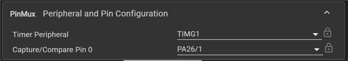
Set up PWM SysConfig

The code uses timer TIMG1, channel 0, to drive PA26. There's no interrupt involved. The duty cycle gets adjusted in the regulation loop.

At this point, I have set the PWM period count to 65535, in an attempt to have the output range identical (but 32768 offset) to the input. 

image

image

Code

note: this design doesn't regulate perfectly yet. At this point in the blog series, all modules are in place and they are tied to the PID. But finetuning PID parameters, input, output, ADC and PWM settings is for post 4.

void perform_pwm() {
    DL_TimerG_setCaptureCompareValue(PWM_0_INST, i32_Output_PID + 32768,
        DL_TIMER_CC_0_INDEX); // update ccr0 value  
}


int main(void) {
    SYSCFG_DL_init();

    // /* timer 5 interrupt ticks per second */ 
    // /* Enable Timer0 NVIC */
    NVIC_EnableIRQ(TIMER_0_INST_INT_IRQN);

    NVIC_EnableIRQ(ADC12_0_INST_INT_IRQN);
    gCheckADC = false;

	/* Initialize the parameters of PID */
	Initialize_PID_Parameter();

    /* Start PWM */
    DL_TimerG_startCounter(PWM_0_INST);

    /* Start Timer counting */
    DL_TimerG_startCounter(TIMER_0_INST);    

    while (1) {
        if (perform) {
            perform = false;
            DL_GPIO_setPins(GPIO_GRP_LEDS_PORT,
                GPIO_GRP_LEDS_PIN_LED_GREEN_PIN);

            perform_adc();
            
            perform_pid();

            perform_pwm();

            DL_GPIO_clearPins(GPIO_GRP_LEDS_PORT,
                GPIO_GRP_LEDS_PIN_LED_GREEN_PIN);
        }
    }
}

void perform_pid() {
    /* Execute PID control in every TM0 interrupt. */
    i32_Output_PID = PID(&PID_Var, i32_Target_Command, gAdcResult);
}

If you compare the perform_pid() with the one from the previous post, you 'll see that it now uses ADC as feedback, and output to drive the PWM.

Demo circuit

I used the same (random) low pass filter as in  MSP432 and TI-RTOS: PID Library Part 2 - Real World Example , to turn the PWM into a DC signal.

image

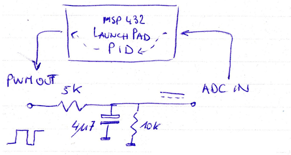
The filter sits between PWM out  (P26) and ADC in (PA25).

You don't have permission to edit metadata of this video.
Edit media
x
image
Upload Preview
image

ccs project for EasyL1105: pid_EasyL1105_20251002_02.zip

Related posts

  • Sign in to reply

Top Comments

  • Jan Cumps
    Jan Cumps 18 days ago in reply to colporteur +1
    It's a Control Technique algorithm. A function that will try to regulate a process' output, in relation to a desired setting. First used in 1911. It requires that you give it feedback on the current…
Parents
  • shabaz
    shabaz 25 days ago

    After a lot of tweaking, it's still not perfect, but I think acceptable.

    For the results in the chart below, I initially set a temperature of 70 degrees, and experimented with adding an aluminium thermal mass on top briefly to force the temperature down by a few degrees, and then removing it to see the response back to the set temperature.  I kept the mass on top at one stage (labeled Kept Mass), to see the temperature recover with the mass present too.

    Then, I reduced the set temperature by two degrees to 68 degC, then increased it back to 70 degrees, then set it to 150 degC, then again did the thermal mass test, then finally turned the set temperature down to 100 degC.

    From the chart, what can be determined is that there is overshoot, I struggled to tame that, and didn't succeed. The overshoot is usually under 1.5 degC, but under certain conditions (such as deliberately cooling the system by about 6-8 deg C by temporarily adding a thermal mass and then removing it), when it tries to recover, the overshoot can reach about 2.5 degC.

    The damping occurs reasonably well, the error is under 0.5 degC often within the first oscillation, before it dampens out. Maybe it would be better for the system to slowly approach the temperature so that it doesn't overshoot or undershoot at all.Or maybe I'm being too picky. Apparently 3D printer hot end control systems overshoot too, and even 5 degC is considered acceptable for that use-case.

    The undershoot shown in the chart below (when lowering the set temperature) is better than the overshoot; usually under 1 degC.

    The PID code is complicated now, it kicks in the 'I' portion only within a certain range for instance. I relied heavily on Chat GPT to handle that.

    In summary, although it functions, I'm sure performance could be improved a lot, by control system experts. But, for the actual end application (heating punches for leather), and probably a whole load of other applications, I think the current performance may be acceptable (it took an entire day of tests and tweaks to get it to this state: (

    I hope the control system doesn't have any unexpected behavior under certain conditions, but I'll find out over time, as it gets used. I need to move on to the PCB, to get the project into at least a usable state.

    image

    • Cancel
    • Vote Up 0 Vote Down
    • Sign in to reply
    • More
    • Cancel
  • shabaz
    shabaz 24 days ago in reply to shabaz

    Video of the annoying flicker! The display is very bright, and the large temperature digits are readable from at least a couple of metres away, which is really nice, but cosmetically it's ruined by the flicker.

    I know of some methods to significantly reduce this, but all of them will no longer be general-purpose (currently I can place arbitrary text on the display), but if sticking to numbers only, it should be possible to pre-render and store in Flash, and that would fit in the MSPM0. Anyway, that's a mini-project in itself, for now, I'll leave the flicker as-is : (

    You don't have permission to edit metadata of this video.
    Edit media
    x
    image
    Upload Preview
    image

    • Cancel
    • Vote Up 0 Vote Down
    • Sign in to reply
    • More
    • Cancel
Comment
  • shabaz
    shabaz 24 days ago in reply to shabaz

    Video of the annoying flicker! The display is very bright, and the large temperature digits are readable from at least a couple of metres away, which is really nice, but cosmetically it's ruined by the flicker.

    I know of some methods to significantly reduce this, but all of them will no longer be general-purpose (currently I can place arbitrary text on the display), but if sticking to numbers only, it should be possible to pre-render and store in Flash, and that would fit in the MSPM0. Anyway, that's a mini-project in itself, for now, I'll leave the flicker as-is : (

    You don't have permission to edit metadata of this video.
    Edit media
    x
    image
    Upload Preview
    image

    • Cancel
    • Vote Up 0 Vote Down
    • Sign in to reply
    • More
    • Cancel
Children
No Data
element14 Community

element14 is the first online community specifically for engineers. Connect with your peers and get expert answers to your questions.

  • Members
  • Learn
  • Technologies
  • Challenges & Projects
  • Products
  • Store
  • About Us
  • Feedback & Support
  • FAQs
  • Terms of Use
  • Privacy Policy
  • Legal and Copyright Notices
  • Sitemap
  • Cookies

An Avnet Company © 2025 Premier Farnell Limited. All Rights Reserved.

Premier Farnell Ltd, registered in England and Wales (no 00876412), registered office: Farnell House, Forge Lane, Leeds LS12 2NE.

ICP 备案号 10220084.

Follow element14

  • X
  • Facebook
  • linkedin
  • YouTube