


A real hardware test of the port of the very good Arduino PID library to MSP432 LaunchPad and TI-RTOS.
PID is a control algorithm. It tries to keep the output of a device at a desired level by controlling its input. Part 1 describes the port from Arduino C++ to C. This part, we generate a DC voltage with the LaunchPad, sample that, and keep its level under control with the PID library.
I'll also introduce a few advanced RTOS principles:
|
What you need:
- MSP432 LaunchPad
- 1 micro-USB cable
- Code Composer Studio
- TI-RTOS for MSP43X
- three 10K resistors and a 4µ7 capacitor (or whatever spare parts you happen to find on your desk)
- a solder iron or a breadboard with a few wires
- a voltmeter or oscilloscope (both optional)
What are we Trying?
It's Control Theort time.
We're making a device that's able to manage to keep a voltage at a certain level.
We'll have three parts:
- PID engine from the previous blog manages the voltage. It uses two other components to do that.
- PWM module generates a block signal. An RC filter converts that to DC. Our PID engine can modify the duty cycle (and as a result the DC level).
- ADC module samples the DC and hands that data over to PID
The PID will constantly play with the PWM module until the DC matches the requested level.
RC Filter
Our MSP432 doesn't have a DAC module. We can't generate an analog value straight away.
It does have a PWM module however. That generates a block wave. We can control the frequency and the duty cycle.
The higher the duty cycle, the more energy our PWM signal holds.
We can use an RC filter to turn that energy into a DC signal. The DC signal's voltage is proportional to the duty cycle of your PWM signal (not to its frequency).

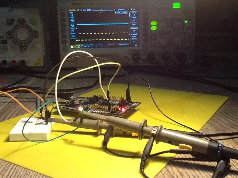
On the scope trace here you can see the yellow PWM signal that's generated by the MSP432. That goes into our RC filter.
The duty cycle of that signal is just a little above 86%.
The blue trace is the DC output of that filter. It's almost 2V.
If the duty cycle of the PWM is set below 86%, the DC signal will decrease. It's at max when the duty cycle is 100%, 0V when the duty cycle is 0%.

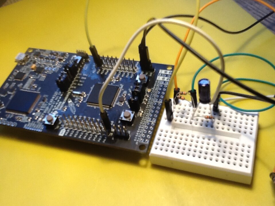
The RC filter is 3 components. You have a 5K resistor and a 4µ7 capacitor that filter the PWM into DC.
The 10K resistor in parallel with the capacitor keeps the voltage to the output below the ADC reference (together with the 5K resistor it acts as a 2/3 voltage divider). It's also a bleeder resistor that discharges the capacitor when you disconnect the filter from its input for some reason.
You can make the 5K from two parallel 10K resistors. That keeps the BOM down to a single very common value.
These values aren't critical at all. Anything that's in the ballpark of what I'm showing here will work.
You can also change the PWM frequency if you have different components lying around.
Connect the input of the RC filter to the output of your LaunchPad's PWM signal. We will use P2.6.
Wire the ground of the filter to one of the many ground pins on the LaunchPad.
The output needs to go to P5.5,
You can check in the PWM and ADC setup sections later in this blog how and why these pins are configured and used.
The TI-RTOS FirmWare - Synchronise with Mailboxes and Events
The CCS project is attached to this post. You can us it to check out some neat RTOS techniques: Messaging, Events and Synchronisation.
There are three tasks.
- PID task manages everything. It's scheduled to run at a given interval by the TI-RTOS.
It asks samples from the ADC module and tells the PWM task to change its duty cycle. - The PWM task sleeps until it gets a command from the PID task to change the duty cycle.
- The ADC task sleeps until it gets a nodge from PID to give the sampled DC value.
Message and Event
We're using the Mailbox functionality to exchange the data between the two tasks. Mailbox has synchronisation built in.
You can let a task wait until it's either told to read a message or write one.
The PID task that's scheduled by the RTOS is the one that tells the other tasks to do their work.
The PWM task sleeps (idle, no cpu time consumed) and waits for a read event.
    while (1) {
        /* wait for mailbox to be posted by writer() */
        if (Mailbox_pend(mbPWM, &msg, BIOS_WAIT_FOREVER)) {
            PWM_setDuty(pwm1, msg.pwm);
        }
    }
When the PID task decides that the PWM duty cycle needs to change (because the output isn't at the right level), it sends a message.
             if (pidCompute()) {
                 pMsg.pwm = trunc(Output);
                 /* enqueue message */
                 Mailbox_post(mbPWM, &pMsg, 10);
The PWM task that was idle all the time wakes up (magic of RTOS - it sends a read event if you define that), reads the message and sets PWM to the what was requested in that message.
Then the PWM goes idle until it receives a new message.
The ADC task sleeps, unless there's a place on the message box (and there's only one place available) to write data.
    while (1) {
        /* Blocking mode conversion */
        ADC_convert(adc0, &adcValue0);
        msg.adc = adcValue0;
        /* enqueue message */
        /* wait for mailbox to be read by reader() */
        Mailbox_post(mbADC, &msg, BIOS_WAIT_FOREVER);
    }
The PID task will make a place available in that mailbox by reading the available message.
If there's no sample available it doesn't wait. We want the PID task to never block. It should run at a steady pace.
         if (! Mailbox_pend(mbADC, &aMsg, BIOS_NO_WAIT) == 0) { // no sample
             Input = aMsg.adc; // todo set to same base as output
            // send to PID library and change PWM when needed

            // ...

         }
A full cycle of the PID task is:
     while (1) {
         Task_sleep(((UInt)arg0));

         if (! Mailbox_pend(mbADC, &aMsg, BIOS_NO_WAIT) == 0) { // no sample
             Input = aMsg.adc; // todo set to same base as output
             // some calculations that you can check in the source code are removed
             if (pidCompute()) {
                 pMsg.pwm = trunc(Output);
                 /* enqueue message */
                 Mailbox_post(mbPWM, &pMsg, 10);
             }
         }
    }
The messages are a very simple structure that we define ourselves:
typedef struct MsgPWM {
    uint32_t pwm;
} MsgPWM;

typedef struct MsgADC {
    uint32_t adc;
} MsgADC;
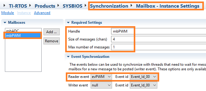
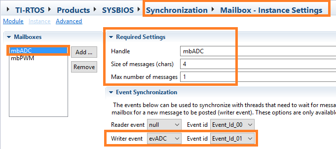
Their size is important, because the Mailbox mechanism makes a byte per byte copy of them when sending and receiving.
You can see in the screenprints of the Mailbox setups above that I enter a char size of 4. That's because the structure of the message contains one 32 bit value. That's 4 chars.
The PWM Module Setup
By default, the MSP432 LaunchPad configures two PWM pins. They both go to one of the LEDs on the board.
We route it to pin P2.6. Check the PWM post of this series for the details (read it if you don't understand what the code snippet below is doing)
You change that in the file MSP_EXP432P401R.c.
const PWMTimerMSP432_HWAttrsV1 pwmTimerMSP432HWAttrs[MSP_EXP432P401R_PWMCOUNT] = {
    {
        .timerBaseAddr = TIMER_A1_BASE,
        .clockSource = TIMER_A_CLOCKSOURCE_SMCLK,
        .compareRegister = TIMER_A_CAPTURECOMPARE_REGISTER_1,
        .gpioPort = GPIO_PORT_P2,
        .gpioPinIndex = GPIO_PIN6,
        .pwmMode = GPIO_PRIMARY_MODULE_FUNCTION
    },

// ...

    /* Use Port Map on Port2 get Timer outputs on pins with LEDs (2.1, 2.2) */
    const uint8_t portMap [] = {
        PM_NONE, PM_NONE, PM_TA1CCR2A, PM_NONE,
        PM_NONE, PM_NONE,     PM_TA1CCR1A,     PM_NONE
    };
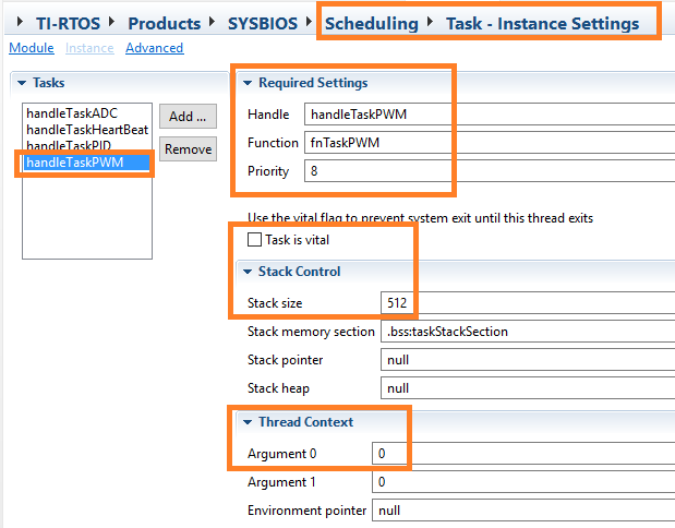
In our PWM task's initialisation section, we arm PWM:
Void fnTaskPWM(UArg arg0, UArg arg1)
{
PWM_Handle pwm1;
PWM_Params params;
uint32_t pwmCounts = PWM_PERIOD;
MsgPWM msg;
PWM_Params_init(¶ms);
params.dutyUnits = PWM_DUTY_COUNTS;
params.dutyValue = 0;
params.periodUnits = PWM_PERIOD_COUNTS;
params.periodValue = pwmCounts;
pwm1 = PWM_open(Board_PWM0, ¶ms);
if (pwm1 == NULL) {
System_abort("Board_PWM0 did not open");
}
PWM_start(pwm1);
while (1) {
// the wile loop is described above, in the TI-RTOS section
This task isn't scheduled to run at regular times in RTOS. It doesn't use the Task_sleep() function like the PID task.
That's because the Message Box schedules it.
The ADC Module Setup
Here, we're doing the same as in the ADC blog of this series. Our ADC input is pin 5.5, with a reference level of 2.5V, 14-bit.
const ADCMSP432_HWAttrs adcMSP432HWAttrs[MSP_EXP432P401R_ADCCOUNT] = {
    {
        .channel = ADC_INPUT_A0,
        .gpioPort = GPIO_PORT_P5,
        .gpioPin = GPIO_PIN5,
        .gpioMode = GPIO_TERTIARY_MODULE_FUNCTION,
        .refVoltage = REF_A_VREF2_5V,
        .resolution = ADC_14BIT
    },
    // ...
The initialisation:
Void fnTaskADC(UArg arg0, UArg arg1)
{
ADC_Handle adc0;
ADC_Params params;
uint16_t adcValue0;
MsgADC msg;
ADC_Params_init(¶ms);
adc0 = ADC_open(Board_ADC0, ¶ms);
while (1) {
// the wile loop is described above, in the TI-RTOS section
The RTOS configuration for the task is identical to that op the PWM job.
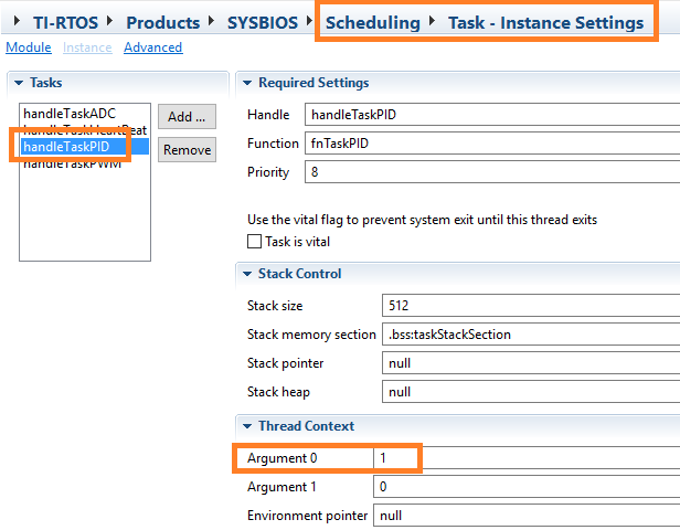
The PID Loop
Finally the PID initialisation:
Void fnTaskPID(UArg arg0, UArg arg1)
{
    MsgADC      aMsg;
    MsgPWM      pMsg;
    //Define Variables we'll be connecting to
    double Setpoint, Input, Output;
    //Specify the links and initial tuning parameters
    double Kp= 1; // one duty cycle count
    double Ki=4, Kd=0; // todo make these good values for our strategy
    Input = 0.0;
    //initialize the variables we're linked to
     Setpoint = PID_BASE;
     Setpoint *= 0.25; // relative to the ADC reference value (2V5)
     pidInit(&Input, &Output, &Setpoint, Kp, Ki, Kd, PID_DIRECT);
     pidSetOutputLimits(0, PID_BASE);
     pidSetSampleTime(arg0);
     //turn the PID on
     pidSetMode(PID_AUTOMATIC);

     while (1) {
    // the wile loop is described above, in the TI-RTOS section
You can hook up a voltmeter over the output of the RC filter and measure the output level.
If you want to check out what's happening with a scope, the interesting signals are the filters input (PWM signal) and output (DC with ripple)
Check out the project code. It's attached to this blog.
Here are some things you can change in the code and see what's happening:
- define another set value by changing the multiplier. 0 = 0%, 1 = 100%
Setpoint *= 0.25; // relative to the ADC reference value (2V5)
- change the PID parameters
    double Kp= 1; // one duty cycle count
    double Ki=0, Kd=0; // todo make these good values for our strategy
- change the control loop frequency. Argument 0 contains the sleep time in microseconds.
- look at the order of events. Is the sample taken at the right time?
Enjoy!
Top Comments