


|
shabaz designed a development kit for the recent Texas Instruments MSPM0 microcontroller series.
|

Goal of this 1st post
- select a PID algorithm that's fit for an MSPM0, without floating point
- set up a timer that makes the code execute on precise intervals
- have a heartbeat pulse to monitor time health (via green LED, counter or scope)
- make it build and execute
Not a goal in post 1: ADC, PWM. Conversion to PID savvy UOM of both. Tuning the PID algorithm.
Most of this stage of the design is borrowed from examples and previous posts.
|
resources used
|
Framework: PID algorithm
The ARM M0 doesn't have floating point hardware. I found a PID example that is written by Nuvoton for that family (see resources used). I'm using both the PID algorithm and the timer approach.
- wait for a timer tick, 5 times per second
- call the PID algorithm to keep the circuit controlled
int32_t PID(PIDC_T* C, int32_t i32_Cmd, int32_t i32_Feedback)
{
    int32_t output;

    /* Calculate error */
    C->i32_Err = i32_Cmd - i32_Feedback;

    /* Integral calculation */
    C->i32_I += C->i32_Ki * C->i32_Err;

    /* PID calculation */
    output = C->i32_Kp * C->i32_Err + C->i32_I + C->i32_Kd * (C->i32_Err - C->i32_Last_Err);

    /* Set output in Q15.0 format */
    output = output >> 15;

    if(output > C->i32_Out_Limit)
        output = C->i32_Out_Limit;
    else if(output < -C->i32_Out_Limit)
        output = -C->i32_Out_Limit;

    /* Update last error */
    C->i32_Last_Err = C->i32_Err;

    /* Return the output of PID Controller */
    return output;
}
What I changed: I don't do the PID (or any other logic) in the timer handler. The handler just sets a flag, and the loop() executes the logic if that flag is set. This is an architectural choice. We 'll have to do ADC, PID and PWM. I prefer not to have all of that executed in an interrupt handler. For low power designs, I'd leave it in the interrupt.
void perform_pid() {


    /* Execute PID control in every TM0 interrupt. */
    i32_Output_PID = PID(&PID_Var, i32_Target_Command, i32_Plant_Signal);

    /* Following is for test only */
    /* Simulate it is unit gain feedback */
    i32_Plant_Signal = i32_Output_PID;	// TODO: this is test code. need to define correct feedback based on sensor hw

    // TODO: add PWM
    cnt++; // TODO: remove test

}
int main(void) {
    // ...

	/* Initialize the parameters of PID */
	Initialize_PID_Parameter();

    // ...

    while (1) {
        if (perform) {
            perform = false;
            // ...

            perform_pid();

            // ...
        }
    }
}
The PID algorithm uses Q15 format, to represent - and calculate with - floating points as integers.
|
What does AI say about Q15 format? The Q15 format, also known as the 1.15 format, is a fixed-point number representation that uses 16 bits to store a two's complement signed fractional number, with one bit for the sign, zero bits for the integer part, and 15 bits for the fractional part. It is commonly used in Digital Signal Processing (DSP) for representing numbers in the range of -1.0 to +0.999969482, where the value is the stored integer divided by 2^15.
How it Works
Example
Why Use Q15?
|
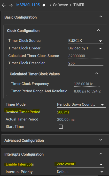
Framework: Timer
The timer logic is based on a TI example for this controller (see resources used). It fires an interrupt 5 times per second.
There's a little bit of setup in main():
int main(void) {
    SYSCFG_DL_init();

    // /* timer 5 interrupt ticks per second */
    // /* Enable Timer0 NVIC */
    NVIC_EnableIRQ(TIMER_0_INST_INT_IRQN);

	// ...

    // /* Start Timer counting */
    DL_TimerG_startCounter(TIMER_0_INST);

    while (1) {
        if (perform) {
            perform = false;

            // ...

            perform_pid();

            // ...
        }
    }
}
Our handler checks if it's the right interrupt. Then sets a flag and moves on.
volatile bool perform = false;

void TIMER_0_INST_IRQHandler(void) {
    switch (DL_TimerG_getPendingInterrupt(TIMER_0_INST)) {
        case DL_TIMER_IIDX_ZERO:
            perform = true;
            break;
        default:
            break;
    }
}
Framework: heartbeat and placeholders for ADC and PWM
With the timer in place, and the PID executed after each tick, we're ready to put in some hooks for the next parts:
an empty implementation for the ADC and PWM logic. These will be implemented in the next posts.
void perform_adc() {
    // TODO: implement
}

void perform_pwm() {
    // TODO: implement
}
Add a heartbeat, and ADC + PWM calls to the loop()
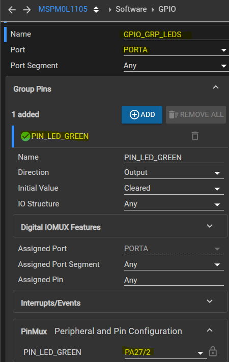
The heartbeat gives an option to externally monitor if we're staying within timer limits. A pin is pulled high when an end-to-end cycle starts, and switched off when finished. I've used the EasyL1105 pin that has the green LED attached. Although it 'll be barely visible, you can use it to check that the code runs every 200 ms. For better control, add an oscilloscope or counter.
    DL_TimerG_startCounter(TIMER_0_INST);

    while (1) {
        if (perform) {
            perform = false;
            DL_GPIO_setPins(GPIO_GRP_LEDS_PORT,
                GPIO_GRP_LEDS_PIN_LED_GREEN_PIN);

            perform_adc();

            perform_pid();

            perform_pwm();

            DL_GPIO_clearPins(GPIO_GRP_LEDS_PORT,
                GPIO_GRP_LEDS_PIN_LED_GREEN_PIN);
        }
    }
}
Thanks for reading. Next, get ADC working.
ccs project for EasyL1105: pid_EasyL1105_20250925.zip
This post contains AI generated info. This info is put in a table with pink coloured background.
-

Jan Cumps
-
Cancel
-
Vote Up
0
Vote Down
-
-
Sign in to reply
-
More
-
Cancel
Comment-

Jan Cumps
-
Cancel
-
Vote Up
0
Vote Down
-
-
Sign in to reply
-
More
-
Cancel
Children