


This is a continuation of my previous post. If you haven't seen it yet, I would strongly recommend taking a look, since we'll be continuing from where we left off. Everything mentioned and used in the project is located in my GitHub repo.
Previously I was able to make a design, which would collect 2048 samples across a full rotation of a quarter wave plate (QWP). Samples are read as 16bit numbers. If we were to constantly send arrays of 2048 readings, we'd have to send 32kb of data per cycle. Current hardware can run at ~24cycles/s which means 768kbps, which might not seem like much, but with a 100MHz system clock, our UART can achieve only 230400 baud rate, which is insufficient. To utilize the full performance we can process data on the FPGA, and then send it over UART to the host PC.
DSP Introduction
To do this, we'll have to implement a digital signal processing (DSP) module. Typically DSPs are used to implement different filters, etc. For this project, we'll take a look at a different approach. But before that, we'll have to know a little bit about the signal that we're working with. By using Mueller calculus, we can calculate the intensity of light transmitted through a rotating QWP and a linear polarizer. Well assume that the angle of QWP is ωt+δ. We can also assume that the angle of the polarizer is θ. Intensity of the light can then be written as:
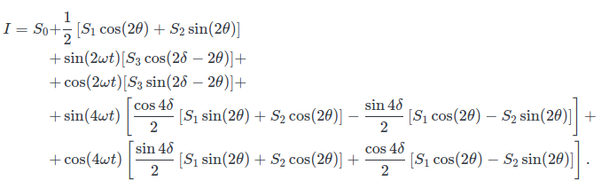
Here different S represent the Stokes parameters, which is what we want to measure. We can see that our signal will carry 5 components, a DC component along with 2 AC components at double the rotation frequency and 2 AC components at quadruple frequency. Therefore we should create a DSP that will measure/read these 5 components. By doing this, we can directly obtain the values of expressions written in the square brackets.
DSP Implementation
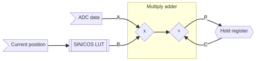
There are multiple approaches, for example, we could do a fast Fourier transform. A more efficient approach is just to get the 5 components directly. This can be done similarly to how it is done in spectrum analyzers or lock-in amplifiers. We can simply take our signal, mix it with reference frequency and integrate it. Mixing signals simply means multiplying them together. So to do this in FPGA we should sample the signal using an ADC, then multiply it with a correct value of sine/cosine for the current position. After that, the product should be added together with previous products. The flow of this is roughly shown in the following diagram.
As we can see, we'll need to provide the values of sine/cosine. There are multiple approaches. For example, we could create a Block RAM, configure it as ROM and then fill it with data. Luckily Xilinx already provides the tools, that do this automatically. Using the DDS compiler IP, we can configure it to SIN/COS LUT. This way a ROM populated with values of sine/cosine will be created automatically. To interface it, we can use a simple AXI Stream to set the phase data (the argument of sine/cosine) and then read it on the output AXI Stream. Setting the phase is extremely simple as we just write the 32bit phase input and set the tvalid signal high. Data is output from the LUT in the same way.
Since we're working with a quadrature encoder with 512 counts per revolution, we'll get 2048 (11bits wide) positions in a single revolution. This way we'll need to configure the double frequency LUT to 10bit depth and the quadruple frequency LUT to 9bit depth. Next is the selection of LUT width (output resolution). This can be determined such that the smallest difference between two consecutive entries in the LUT are greater than 1. For a 10bit deep LUT, the width should be 16bits or wider.
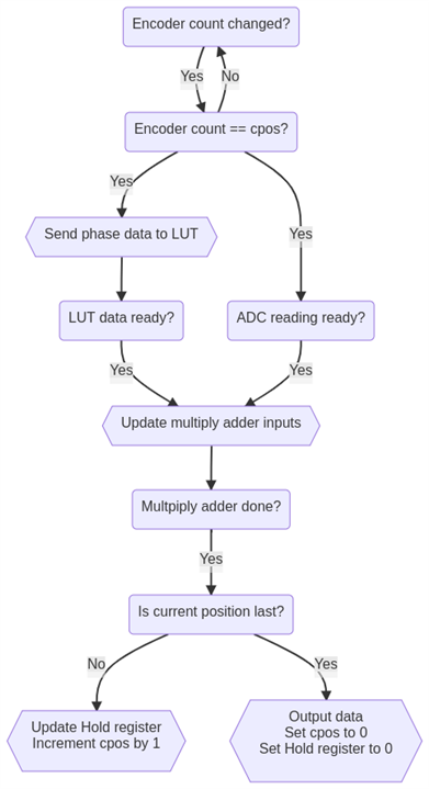 Finally, we'll need some logic, that will move data between the ADC, LUTs, multiply adders, internal hold register and outputs. The operation is relatively simple. When the encoder count changes to the desired position, we'll update the input of the LUTs. When LUTs and ADC have data ready, we'll write their output values to 4 multiply adders (MADD) to A and B inputs. We'll also write the ADC data directly to the single Adder IP. MADDs need 3 cycles to perform the multiplication and addition. When they are done, we'll write their outputs to 5 hold registers and C inputs on the MADDs. Similarly, the output of the adder is written back to the B input. Finally, we increment the desired position by 1. If we are in the last position we write data from all 5 hold registers to outputs, after which we reset the value of hold registers to 0. Additionally, the DSP controller outputs a data-ready signal to the interrupt input of the MicroBlaze.
`timescale 1ns / 1ps


module DSP_controller(
    //General signals
    input               fpga_clk_i,
    input               nres_i,

    //ADC signals
    input               adc_data_ready_i,
    input       [15:0]  adc_data_i,

    //Encoder signal
    input       [10:0]  encoder_cnt_i,

    //Multiply adder p signals
    input       [47:0]  madd_sin1f_p,
    input       [47:0]  madd_cos1f_p,
    input       [47:0]  madd_sin2f_p,
    input       [47:0]  madd_cos2f_p,

    //Multiply adder c signals
    output reg  [47:0]  madd_sin1f_c,
    output reg  [47:0]  madd_cos1f_c,
    output reg  [47:0]  madd_sin2f_c,
    output reg  [47:0]  madd_cos2f_c,

    //Multiply adder b adc_data
    output reg  [15:0]  madd_sin1f_b,
    output reg  [15:0]  madd_cos1f_b,
    output reg  [15:0]  madd_sin2f_b,
    output reg  [15:0]  madd_cos2f_b,

    //Adder s signal
    input       [31:0]  add_s,

    //Adder b signal
    output reg  [31:0]  add_b,

    //Adder and Multiply adder a signal
    output reg  [15:0]  adc_data,

    //Output registers
    output reg  [31:0]  res_0f,
    output reg  [47:0]  res_sin1f,
    output reg  [47:0]  res_cos1f,
    output reg  [47:0]  res_sin2f,
    output reg  [47:0]  res_cos2f,

    //Double frequency (10bit wide) sin/cos lookup table phase data AXI stream output
    output      [15:0]  m0_axis_phase_tdata,
    output              m0_axis_phase_tvalid,

    //Double frequency (10bit wide) sin/cos lookup table AXI stream data input
    input       [31:0]  s0_axis_data_tdata,
    input               s0_axis_data_tvalid,

    //Quad frequency (9bit wide) sin/cos lookup table phase data AXI stream
    output      [15:0]  m1_axis_phase_tdata,
    output              m1_axis_phase_tvalid,

    //Quad frequency (9bit wide) sin/cos lookup table AXI stream data input
    input       [31:0]  s1_axis_data_tdata,
    input               s1_axis_data_tvalid,

    //Data ready output
    output reg          data_ready_o

);
    reg                 cnt_lsb_del;    //single cycle delayed lsb of encoder_cnt_i
    reg         [10:0]  cpos;   //Current position
    reg         [9:0]  cphase;  //Current phase
    reg                 idle;   //Idle flag
    reg                 m_axis_tvalid;  //Tvalid flag used for AXI stream outputs

    reg                 madd_wait_state;    //Wait state flag for multiply adder
    reg         [1:0]   madd_wait_cnt;  //Wait state duration count for multiply adder


    assign m0_axis_phase_tdata = {6'b0, cphase}; //Set phase input of the 1xfreq DDS (10 bit wide input -1024 different values- as it should go through array twice per period)
    assign m1_axis_phase_tdata = {6'b0, cphase}; //Set phase input of the 2xfreq DDS (9 bit wide input as it should go through array twice per period)

    //Signal that valid data is present on AXI stream outputs
    assign m0_axis_phase_tvalid = m_axis_tvalid;
    assign m1_axis_phase_tvalid = m_axis_tvalid;

    //INITIALS
    initial cpos = 0;
    initial idle = 1;
    initial m_axis_tvalid = 0;
    initial madd_wait_state = 0;
    initial madd_wait_cnt = 0;


    always @(posedge fpga_clk_i) cnt_lsb_del <= encoder_cnt_i[0]; //Get a delayed LSB of encoder count to compare on change for triggering.

    always @(posedge fpga_clk_i)
    begin
        if(~nres_i) //CORE RESET
            begin
                cpos <= 0;
                idle <= 1;
                m_axis_tvalid <= 0;
                madd_wait_state <= 0;
                madd_wait_cnt <= 0;

                madd_sin1f_c <= 0;
                madd_cos1f_c <= 0;

                madd_sin2f_c <= 0;
                madd_cos2f_c <= 0;

                add_b <= 0;
            end
        else
            begin
                if(idle) //Check whether we are idle or not
                    begin
                        if(cnt_lsb_del != encoder_cnt_i[0]) //Check whether the encoder count changed?
                        begin
                            if(cpos == encoder_cnt_i) //Check whether we are in desired position
                            begin
                                cpos    <= cpos + 1;    //Advance for 1 count
                                idle    <= 0;   //Core is not idle anymore
                                cphase  <= cpos[9:0];   //Write phase data to AXI streams
                                m_axis_tvalid <= 1; //Set both tvalid flag to high on both master axis to signal the correct phase on the input of the DDS cores.
                                data_ready_o <= 0;  //Output data is not valid anymore

                            end

                            if(cpos == 0)   //Reset the summation registers and output the generated data -- start of a new cycle
                            begin
                                //Write calculated data to result registers
                                res_sin1f <= madd_sin1f_c;
                                res_cos1f <= madd_cos1f_c;
                                res_sin2f <= madd_sin2f_c;
                                res_cos2f <= madd_cos2f_c;
                                res_0f <= add_b;
                                //Reset the "cary" registers
                                madd_sin1f_c <= 0;
                                madd_cos1f_c <= 0;

                                madd_sin2f_c <= 0;
                                madd_cos2f_c <= 0;

                                add_b <= 0;

                                //Data should be ready now
                                data_ready_o <= 1;
                            end
                        end
                    end
                else //If we're not idle
                    begin

                        if(&{adc_data_ready_i, s0_axis_data_tvalid, s1_axis_data_tvalid, ~madd_wait_state}) //If DDSs and the ADC have data ready
                        begin
                            m_axis_tvalid <= 0; //We got the data from DDSs, so we can reset the tvalid flag

                            madd_sin1f_b <= s0_axis_data_tdata[31:16];  //Output of DDS is 32 bit, higher 16bits represent the value of sine
                            madd_cos1f_b <= s0_axis_data_tdata[15:0];   //Output of DDS is 32 bit, lower 16bits represent the value of cosine

                            madd_sin2f_b <= s1_axis_data_tdata[31:16];  //Output of DDS is 32 bit, higher 16bits represent the value of sine
                            madd_cos2f_b <= s1_axis_data_tdata[15:0];   //Output of DDS is 32 bit, lower 16bits represent the value of cosine

                            adc_data <= adc_data_i; //Write data from adc to Adder/Multiply adder inputs
                            madd_wait_state <= 1;   //Start waiting for multiply adders to finish (3 cycles)
                            madd_wait_cnt <= 2'b11;


                        end

                        if(madd_wait_state)
                        begin
                            if(madd_wait_cnt == 0)  //Multiply adders are done
                                begin
                                    //Move the results from Adder Multiply adders outputs back to their C inputs (B for adder)
                                    madd_sin1f_c <= madd_sin1f_p;
                                    madd_cos1f_c <= madd_cos1f_p;

                                    madd_sin2f_c <= madd_sin2f_p;
                                    madd_cos2f_c <= madd_cos2f_p;

                                    add_b <= add_s;

                                    //Wait state is over
                                    madd_wait_state <= 0;

                                    //Switch back to idle -- wait for new encoder increment
                                    idle <= 1;
                                end
                            else
                                begin
                                    madd_wait_cnt <= madd_wait_cnt - 1;
                                end
                        end


                    end


            end

    end


endmodule
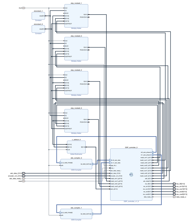
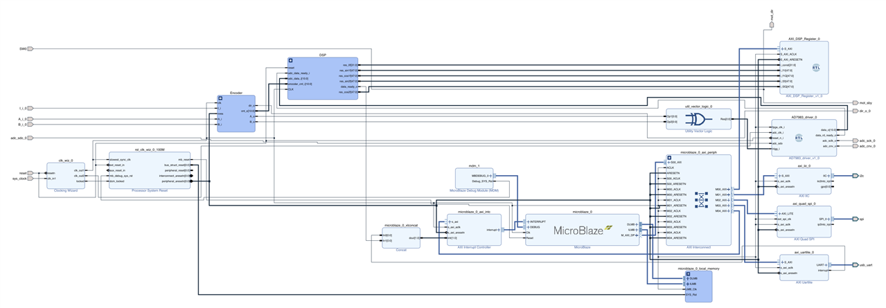
To summarize I have used 2 DDS compilers configured as SIN/COS LUT to generate the reference sine/cosine signals. These then get multiplied using 4 Multiply adders with the signal from the ADC. Additionally, there is an adder which sums up all ADC readings for a single revolution. Finally, there is a custom RTL code which moves data between inputs and outputs. The full DSP "core" can be seen in the following image.
FPGA
To read the data using Microblaze, I have modified the Axi-Lite slave registers such that they now allow 5 outputs, which are connected to the AXI network. Since we now have the DSP to process the ADC data, we can remove the BRAM used in a previous blog post and all of its peripherals. Finally, we can add in the DSP core, which requires the reset and clock signals from the FPGA along with the encoder count and the ADC data output along with ADC data ready output. The DSP core has 5 output registers which hold the results of 5 components in the measured signal. The 4 frequency components are 48bits wide but only the 32 most significant bits can be read using the AXI-Lite slave. This is done because we needed to "divide" the signal by 16bits (65535) since the outputs of the LUTs were 16bits wide (e.g. 65535*sin(x)). Additionally, there is a data-ready signal which is connected to the interrupt on the MicroBlaze.
Everything else is mostly the same as in the previous post.
Microblaze firmware
The firmware running on the Microblaze is extremely simple. First, it configures the motor controller, UART and the interrupts. After that, it simply writes data from 5 32bit wide registers to UART.
//INCLUDES
#include <stdio.h>
#include "platform.h"
#include "xil_printf.h"
#include "xparameters.h"
#include "xintc.h"
#include "xil_exception.h"
#include "xil_io.h"
#include "motor_controller.h"
#include "xiic.h"

//I2C DEFINES
#define IIC_DEVICE_ID	   	XPAR_IIC_0_DEVICE_ID
#define IIC_BASE_ADDRESS	XPAR_IIC_0_BASEADDR
#define IIC_MOTOR_ADDRESS	0x29

//DSP DEFINES
#define DSP_CTRL_ADDR XPAR_AXI_DSP_REGISTER_0_BASEADDR

//INTERRUPT DEFINES
#define INTC_DEVICE_ID		XPAR_INTC_0_DEVICE_ID
#define DSP_INTERRUPT_CHANNEL 1


//FUNCTIONS
void WriteFromDSP(void *CallbackRef);


int main() {
	init_platform();	//Initialize the platform (UART)
	microblaze_enable_interrupts();	//Enable the interrupts

	xil_printf("I: Initializing!\n");
	motor_default_settings(IIC_BASE_ADDRESS, IIC_MOTOR_ADDRESS);	//Configure the motor controller to known usable settings
	motor_configure(IIC_BASE_ADDRESS, IIC_MOTOR_ADDRESS);			//Configure the motor to I2C operation, set number of poles and max RPM
	motor_start_rpm(IIC_BASE_ADDRESS, IIC_MOTOR_ADDRESS, 5);		//Set motor start RPM
	motor_set_speed(IIC_BASE_ADDRESS, IIC_MOTOR_ADDRESS, 400);		//Configure motor setpoint speed (not in rpm e.g. with curren motor setpoint of 400 results in 1440 RPM)
	xil_printf("I: Motor Started!\n");
	xil_printf("I: Configuring Interrupts!\n");


	cleanup_platform();
	//Configure the interrupt channel. This will lead to interrupt getting triggered every time that fresh data is available.
	XIntc_RegisterHandler(XPAR_INTC_0_BASEADDR, DSP_INTERRUPT_CHANNEL, (XInterruptHandler)WriteFromDSP, (void *)1);
	XIntc_MasterEnable(XPAR_INTC_0_BASEADDR);
	XIntc_EnableIntr(XPAR_INTC_0_BASEADDR, 0x3);


}

void WriteFromDSP(void *CallbackRef)
{
	/* Print data that is read from DSP registers. Format is A;B;C;D;E
	 * A corresponds to  the constant component of the signal
	 * B corresponds to the sin(2f) component of the signal
	 * C corresponds to the cos(2f) component of the signal
	 * D corresponds to the sin(4f) component of the signal
	 * E corresponds to the cos(4f) component of the signal
	 */
	xil_printf("%i;%d;%d;%d;%d\r\n", Xil_In32(DSP_CTRL_ADDR),
					Xil_In32(DSP_CTRL_ADDR+4),
					Xil_In32(DSP_CTRL_ADDR+8),
					Xil_In32(DSP_CTRL_ADDR+12),
					Xil_In32(DSP_CTRL_ADDR+16));

}
Using the polarimeter and some measurements.
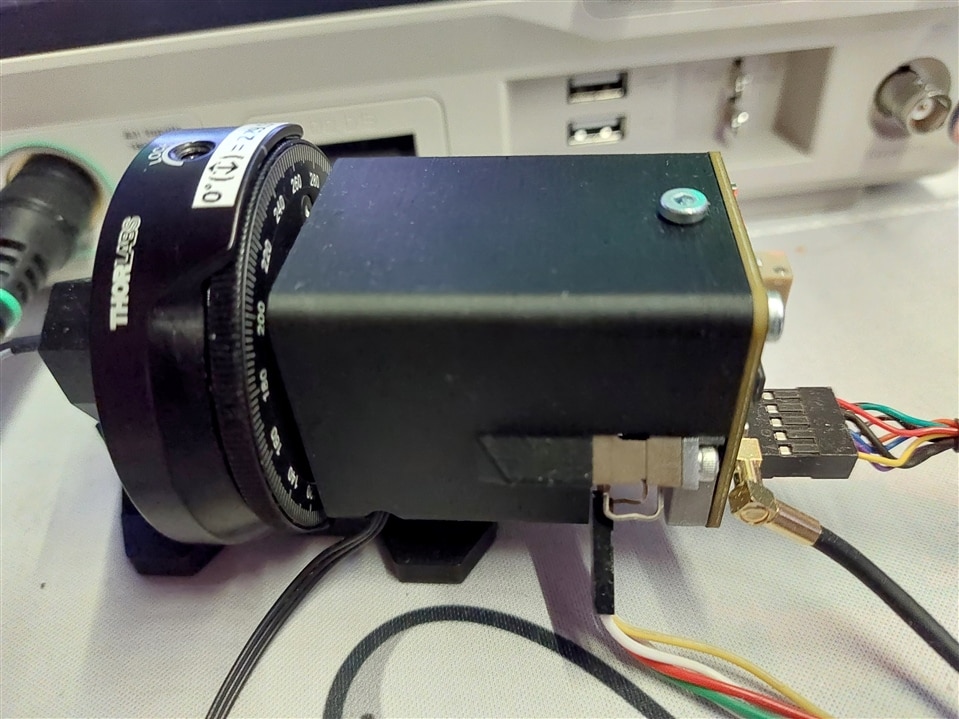
To test everything I have assembled a simple mount that holds a diode laser with optics, followed by a Linear polarizer in a rotation mount. Finally, the polarimeter sensor measures the light transmitted by the polarizer.
To process data, I have written a program in Python which reads data from FPGA and then calculates the Stokes Parameters. The program is threaded such that data reads are done separately from the UI updates. This should prevent any overflowing of the serial buffers.
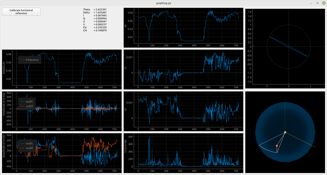
Data from the FPGA is plotted on the left side. Stokes parameters are plotted in the middle. Lastly, I am plotting the polarization ellipse on the top right. In the bottom right, a Poincare sphere is plotted. To use the program a horizontal reference polarization has to be set. This is done by shining a "reference" linear polarized light into the sensor and running the calibration. During the calibration, 100 samples will be collected, which will be averaged and used to compute the values of θ and δ mentioned above.
In the image below we can see a measurement of linearly polarized light. You can also see the history while I was playing with the polarizer.
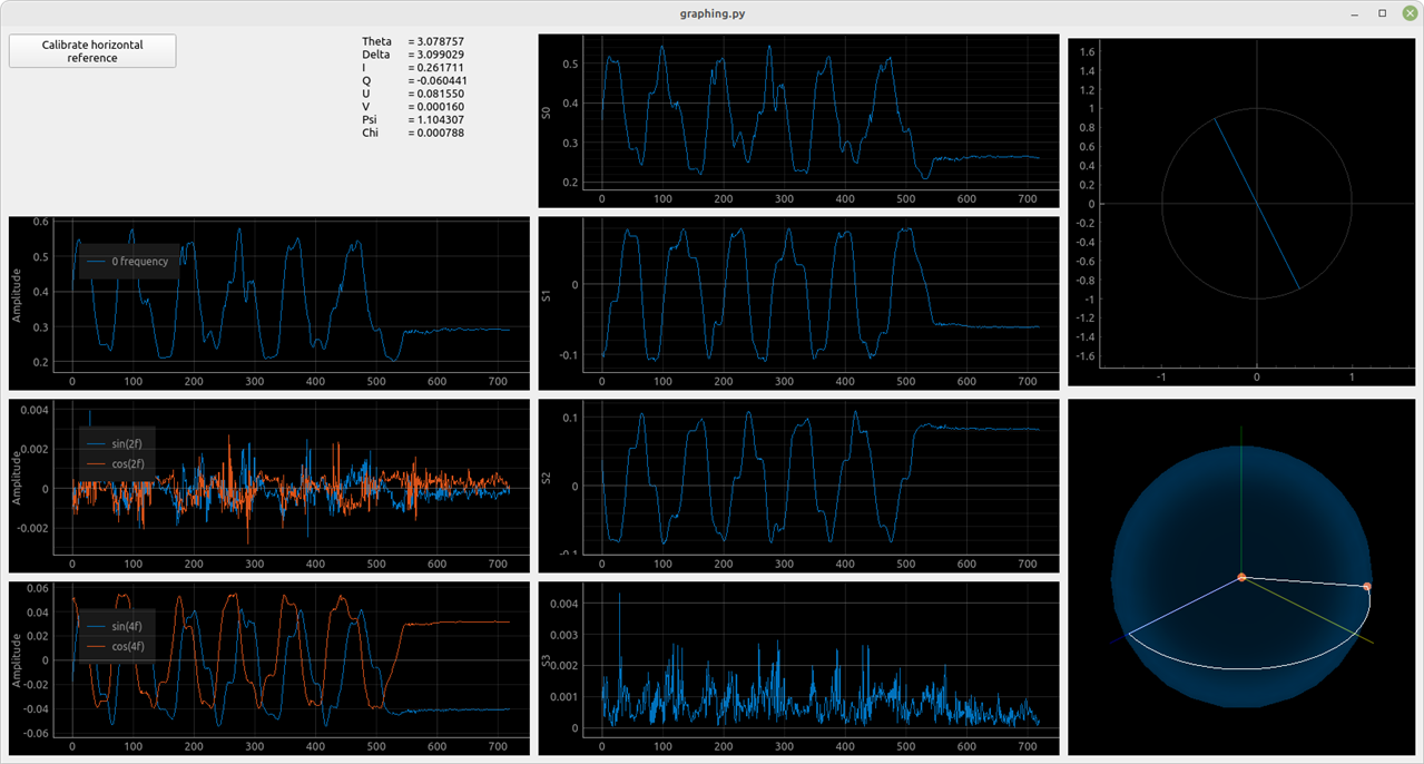
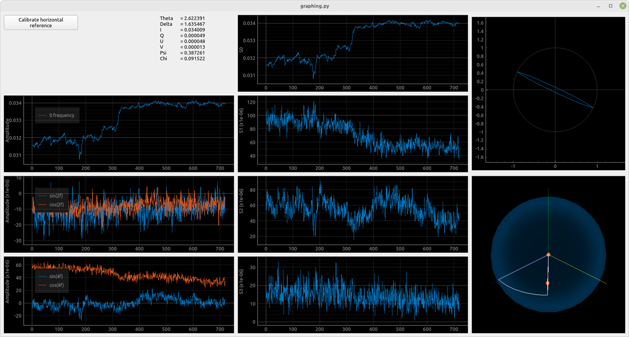
I have noticed, that If I was spinning the polarizer the S0 (or the intensity Stokes parameter) was changing. This is because the laser diode I used was emitting polarized light. And now that I have the tools, I could measure it.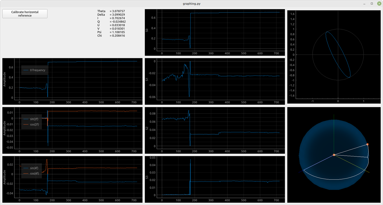
We can see, that the emitted light is elliptical. I also tried getting measurements of different light sources I had on hand. Also, keep in mind that the optical components inside the sensor used are meant for 850nm wavelength.
| {gallery}Random measurements |
|---|
|
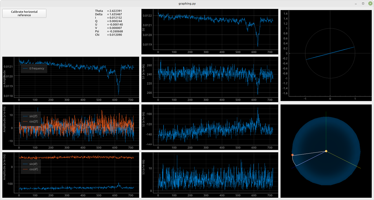
Measured polarization of incandescent light. Small and noisy values S1, S2, and S3 are can be interpreted as unpolarized light. |
|
Measured polarization of a phone flashlight. Light is unpolarized. |
|
Measured polarization of a red laser pointer. Polarization is linear. |
A note on result interpretation
Currently, the software draws a point on a fixed-size sphere and an ellipse with a fixed-size major axis. In the images above I added two examples of unpolarized light, incandescent and LED light. To know whether light is polarized or unpolarized can be determined using a "polarization" factor:
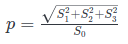
Using this we can evaluate values of p for measurements above:
| Measurement | value of p |
| Linear polarizer | 0.400 |
| Test laser | 0.053 |
| Incandescent light | 0.012 |
| LED | 0.002 |
| Red laser pointer | 0.019 |
As can be seen, the LED is the least polarized, followed by the incandescent. We can see that the initial laser (OPV330, VCSEL technology) used for testing is much more polarized than the red laser pointer, which is probably due to the difference between laser cavities.
Conclusion.
Hopefully, this was as interesting to read as it was to put together. When info about the 7 Ways to Leave Your Spartan-6 was posted, I did not know what to make. Luckily I got a recommendation to build a polarimeter from my mentor. I found the project to be a nice learning experience since I have never worked with any kind of DSP. Furthermore, I truly hope that this was able to showcase some use cases of digital signal analysis. Even though a polarimeter is a niche tool it uses some methods such that a similar FPGA design could be used to make a lock-in amplifier or even a simple spectrum analyzer.
As mentioned in my GitHub repo, this project will also be used as a part of my Master's thesis. Hence I plan to do further work. Currently, it is in the last stages of a "proof of concept". Soon I will try to get it tested in a lab. There are also some important changes incoming, such as an FPGA shield PCB to hold all modules and power supplies. PCB on the sensor with some sort of connector, probably with a custom diode amplifier design. The current Python program is mostly just for testing along with the fact that python is not the best for making standalone software, etc. The ability to control the polarimeter from the host needs to be implemented. I also want to add the ability for the device to be used as an SPI slave, such that it can be used with e.g. a display module or a Raspberry Pi. I am also thinking about porting to a Zynq, which should be relatively simple since we're using a 7-series FPGA (It would be much more difficult if I have used Spartan-6...).
If there are any questions or comments please let me know.
Top Comments