element14 Community
element14 Community
    Register Log In
  • Site
  • Search
  • Log In Register
  • Community Hub
    Community Hub
    • What's New on element14
    • Feedback and Support
    • Benefits of Membership
    • Personal Blogs
    • Members Area
    • Achievement Levels
  • Learn
    Learn
    • Ask an Expert
    • eBooks
    • element14 presents
    • Learning Center
    • Tech Spotlight
    • STEM Academy
    • Webinars, Training and Events
    • Learning Groups
  • Technologies
    Technologies
    • 3D Printing
    • FPGA
    • Industrial Automation
    • Internet of Things
    • Power & Energy
    • Sensors
    • Technology Groups
  • Challenges & Projects
    Challenges & Projects
    • Design Challenges
    • element14 presents Projects
    • Project14
    • Arduino Projects
    • Raspberry Pi Projects
    • Project Groups
  • Products
    Products
    • Arduino
    • Avnet & Tria Boards Community
    • Dev Tools
    • Manufacturers
    • Multicomp Pro
    • Product Groups
    • Raspberry Pi
    • RoadTests & Reviews
  • About Us
    About the element14 Community
  • Store
    Store
    • Visit Your Store
    • Choose another store...
      • Europe
      •  Austria (German)
      •  Belgium (Dutch, French)
      •  Bulgaria (Bulgarian)
      •  Czech Republic (Czech)
      •  Denmark (Danish)
      •  Estonia (Estonian)
      •  Finland (Finnish)
      •  France (French)
      •  Germany (German)
      •  Hungary (Hungarian)
      •  Ireland
      •  Israel
      •  Italy (Italian)
      •  Latvia (Latvian)
      •  
      •  Lithuania (Lithuanian)
      •  Netherlands (Dutch)
      •  Norway (Norwegian)
      •  Poland (Polish)
      •  Portugal (Portuguese)
      •  Romania (Romanian)
      •  Russia (Russian)
      •  Slovakia (Slovak)
      •  Slovenia (Slovenian)
      •  Spain (Spanish)
      •  Sweden (Swedish)
      •  Switzerland(German, French)
      •  Turkey (Turkish)
      •  United Kingdom
      • Asia Pacific
      •  Australia
      •  China
      •  Hong Kong
      •  India
      •  Japan
      •  Korea (Korean)
      •  Malaysia
      •  New Zealand
      •  Philippines
      •  Singapore
      •  Taiwan
      •  Thailand (Thai)
      •  Vietnam
      • Americas
      •  Brazil (Portuguese)
      •  Canada
      •  Mexico (Spanish)
      •  United States
      Can't find the country/region you're looking for? Visit our export site or find a local distributor.
  • Translate
  • Profile
  • Settings
FPGA
  • Technologies
  • More
FPGA
Blog Entering The World Of FPGA's with a DEO-NANO P0082 - Part 5 (modelling a M74HC590)
  • Blog
  • Forum
  • Documents
  • Quiz
  • Events
  • Polls
  • Files
  • Members
  • Mentions
  • Sub-Groups
  • Tags
  • More
  • Cancel
  • New
Join FPGA to participate - click to join for free!
  • Share
  • More
  • Cancel
Group Actions
  • Group RSS
  • More
  • Cancel
Engagement
  • Author Author: e14 Contributor
  • Date Created: 24 Aug 2017 7:17 PM Date Created
  • Views 4960 views
  • Likes 6 likes
  • Comments 28 comments
  • p0082
  • terasic
  • deo-nano p0082
  • de0-nano
  • enterfpga
  • p0082(terasic)
  • terasic p0082 de0-nano fpga development kit
Related
Recommended

Entering The World Of FPGA's with a DEO-NANO P0082 - Part 5 (modelling a M74HC590)

e14 Contributor
e14 Contributor
24 Aug 2017

Ive been recently using an M74HC590 binary counter to capture some data from an opto-encoder and thought that since I'd modelled a basic binary counter into the FPGA, why don't I go the whole hog and model this real world component into it too and make a final blog post in this series.


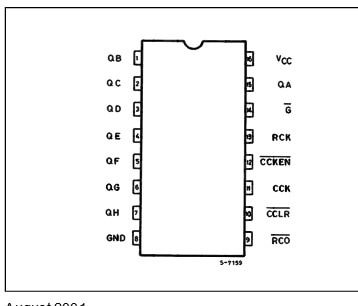
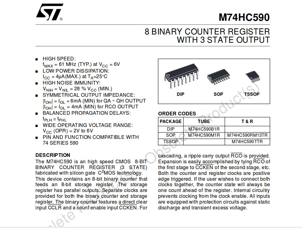
Here's the front page and the pinout  in the datasheet for the M74HC590 that I'll be modelling:
image

image


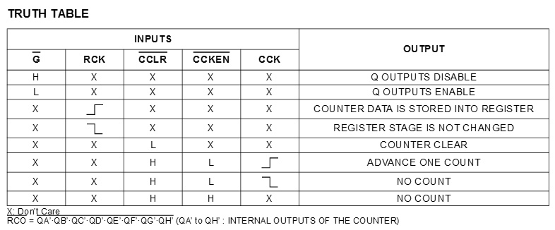
So we know what the inputs and outputs are of the device are but what about the way it functions internally? Well I looked through the datasheet and found a truth table that I could work things out from.
 

image


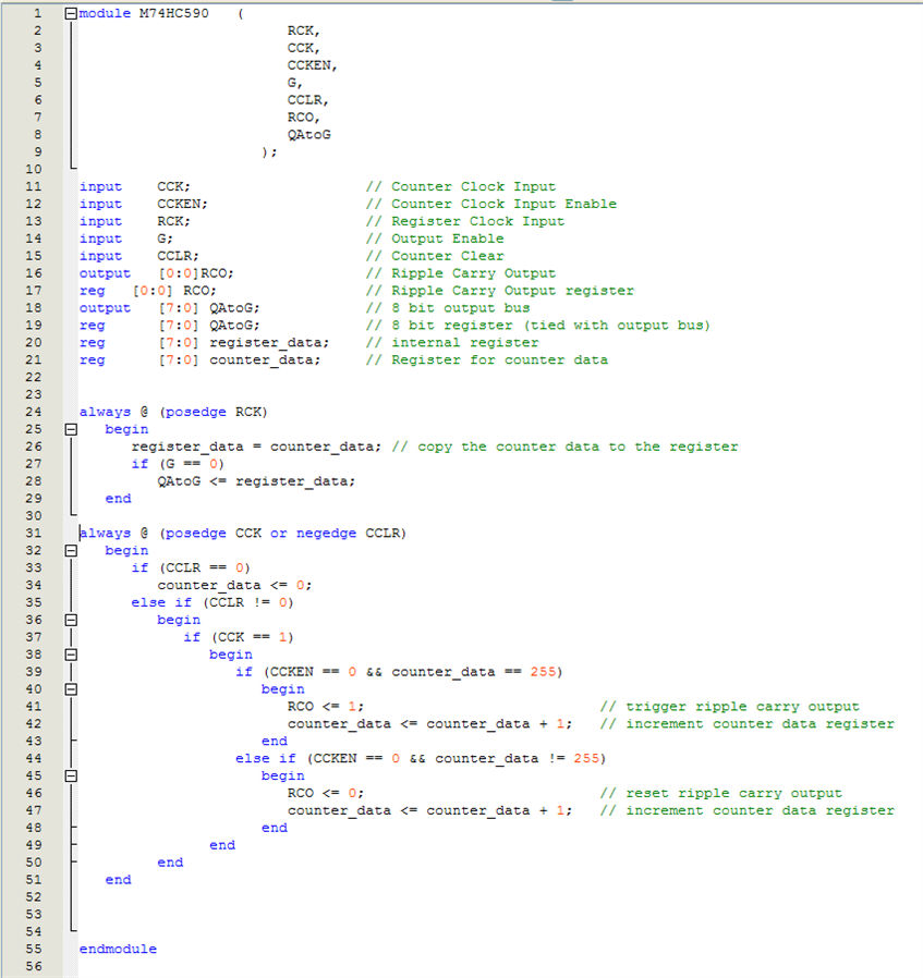
Using this data, I made up the following Verilog file:
 

image


As you can see Ive copied the pin labels etc.. and used nested if's to do most of the logic.


image


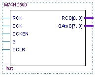
Once were happy with the Verilog file, we generate the board symbol shown here. Theres the corresponding input pins and the output pins QA throught to QG are shown as a single wire representing the 8bit output bus.


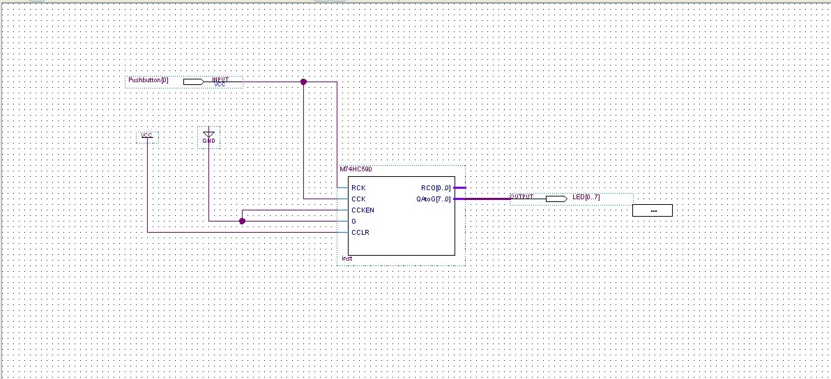
In the following schematic, Ive added the symbol for the Verilog file and made some connections to it:
 

image


The CCKEN and G pins have been connected to an internal Ground and CCLR has been connecting to an internal voltage source (VCC). These could have been broken out to real pins on the DE0-NANO P0082 board and connected manually but I did it this way for simplicity.


The RCK and CCK pins have both been connected to a push button on the development board.


The QA - QG outputs have all been connected to the LED's on the development board and the RCO pin has been left unconnected for the time being. This output would be connected to another 8-bit counter if they were being cascaded into a 16-bit counter.


From here it was just a case of assigning the LED's and pushbutton to the correct pins and the device is ready to test. The video at the bottom of this shows the final programmed development board. Because the CCK and RCK pins were attached to a push button, simply pressing that button causes the device to count up press by press.


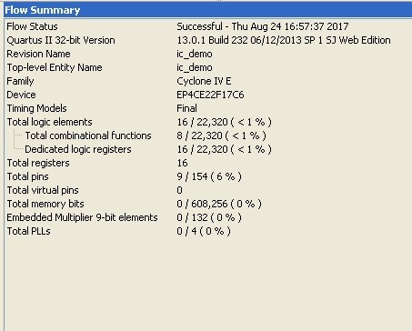
Heres the compiler summary for the above component, very few of the actual resources were used (in most cases less than 1%):
 

image


Hopefully this gives an insight into how fpga's can be utilised by modelling existing components that we already know, this is the final blog post in this mini-series but I will be posting occasional updates of my progress on an rgb led matrix driver that Im working towards with the DE0-NANO. I intend to cheat a little bit to start with and initialise some registers with a test pattern while I work out how to drive the signal properly. Once that's done I can work backwards into a more complex design.
image


You don't have permission to edit metadata of this video.
Edit media
x
image
Upload Preview
image

  • Sign in to reply

Top Comments

  • e14 Contributor
    e14 Contributor over 9 years ago in reply to rachaelp +5
    Yes Im planning on doing another post or 2 when I get underway with the led matrix display driver and then who knows maybe some other project in the future too. Hopefully others will stumble across this…
  • e14 Contributor
    e14 Contributor over 9 years ago in reply to michaelkellett +3
    Thanks for explaining! It does appear to function as expected so I'm going to call it a partial win, although I'm plenty sure that your explanation for why it's not the best way to go about it will become…
  • michaelkellett
    michaelkellett over 9 years ago in reply to e14 Contributor +3
    Good luck - it's good for me to be forced to think about Verilog. I'll try to repeat your code in VHDL in the next few days and post it here so you can see the difference. MK
Parents
  • rachaelp
    rachaelp over 9 years ago

    As johnbeetem gave you his implementation of your design in Verilog, I've gone ahead and thrown something similar together in VHDL. I've not run it through a compiler or checked syntax and it's off the top of my head so I might have got something wrong as I am a tad rusty but here goes:


    library IEEE;
    use IEEE.std_logic_1164.all;
    use IEEE.numeric_std.all;
    
    entity 74HC590 is
    begin
       port (
          CCK   : in  std_logic;                    // Counter clock, rising edge.
          CCKEN : in  std_logic;                    // Counter clock enable, active LOW.
          RCK   : in  std_logic;                    // Register clock, rising edge.
          G     : in  std_logic;                    // Output enable, active LOW.
          CCLR  : in  std_logic;                    // Counter clear, active LOW.
          RCO   : out std_logic;                    // Ripple carry output, active low.
          Q     : out std_logic_vector (7 downto 0) // Chip output, may be high-Z.
       )
    end entity;
    
    architecture RTL of 74HC590 is
    
    signal countVal : std_logic_vector (7 downto 0);
    signal RCO_i    : std_logic;
    signal CCK_last : std_logic;
    
    begin
    
    -- Counter process
    COUNT1: process (RCK) -- Only RCK needs to be in the sensitivity list as the process is fully synchronous.
    begin
       if rising_edge (RCK) then
          countVal <= countVal;
          CCK_last <= CCK;
          if (CCLR = '0') then
             countVal <= X"00";
          elsif (CCKEN = '0') then
             if (CCK = '1' and CCK_last = '0') then
                if (countVal >= X"FF") then
                   countVal <= X"00";
                else
                   countVal <= countVal + X"01";
                end if;
             end if;
          end if;
       end if;
    end process;
    
    RCO_i <= '0' when countVal = X"FF" else '1';
    
    -- Assign to outputs and create the tristate buffers
    Q <= countVal when G = '1' else (others => 'Z');
    RCO <= RCO_i when G = '1' else 'Z';
    
    end architecture;


    It's also possible to have an asynchronous reset but as michaelkellett pointed out, you don't necessarily want to have asynchronous things going on in your FPGA. A global reset can be ok but again you need to be careful to ensure at startup your entire chip comes out of reset at the same time.


    Best Regards,


    Rachael

    • Cancel
    • Vote Up +3 Vote Down
    • Sign in to reply
    • More
    • Cancel
  • jc2048
    jc2048 over 9 years ago in reply to rachaelp

    missing when in line 46?


    I can still remember some of this - perhaps I ought to save up and get myself an FPGA to play with.

    • Cancel
    • Vote Up +3 Vote Down
    • Sign in to reply
    • More
    • Cancel
  • rachaelp
    rachaelp over 9 years ago in reply to jc2048

    Yes you are right. I will fix that. If that's the only error my in my head compiler missed I'll be happy image

    • Cancel
    • Vote Up +3 Vote Down
    • Sign in to reply
    • More
    • Cancel
Comment
  • rachaelp
    rachaelp over 9 years ago in reply to jc2048

    Yes you are right. I will fix that. If that's the only error my in my head compiler missed I'll be happy image

    • Cancel
    • Vote Up +3 Vote Down
    • Sign in to reply
    • More
    • Cancel
Children
No Data
element14 Community

element14 is the first online community specifically for engineers. Connect with your peers and get expert answers to your questions.

  • Members
  • Learn
  • Technologies
  • Challenges & Projects
  • Products
  • Store
  • About Us
  • Feedback & Support
  • FAQs
  • Terms of Use
  • Privacy Policy
  • Legal and Copyright Notices
  • Sitemap
  • Cookies

An Avnet Company © 2026 Premier Farnell Limited. All Rights Reserved.

Premier Farnell Ltd, registered in England and Wales (no 00876412), registered office: Farnell House, Forge Lane, Leeds LS12 2NE.

Follow element14

  • X
  • Facebook
  • linkedin
  • YouTube