Exploring 7 Series MIG Part - 1
Hello, last week I received the Arty S7 board as part of the 7 Ways to Leave Your Spartan 6 Challenge, on power-up LEDs started blinking using the preloaded binaries. Happy to see it working, but I was confused looking at the DDR part on the board. Digilent advertised it to be MT41K128M16XX-15E from Micron, but the part present was PMF511816EBR from Piecemakers. After looking into the timing parameters of both the parts they looked the same, so I decided to test the DDR to make sure it really works.
7 Series FPGAs do not have hard memory controllers instead, they have hard PHY which exposes DFI Interface. DDR Controllers must be used to act as a mediator to provide access between user interfaces say AXI and DFI. Xilinx provides Memory Interface Generator (MIG) memory controller for this purpose.
7 series MIG IP configuration is a bit complicated compared to the new generation MPSoC MIG. Initially, I was not able to find example designs for Arty, and even Arty S7 board automation seems to be broken. So here is the documentation on running the SDK Memory Tests application for initial testing of DDR.
Vivado project creation steps are skipped to reduce the length of this blog, create a new project by selecting the Arty S7-50 board and create a new block design before proceeding.
Click on the Board option under the sources tab. Double click on System Reset and click OK.
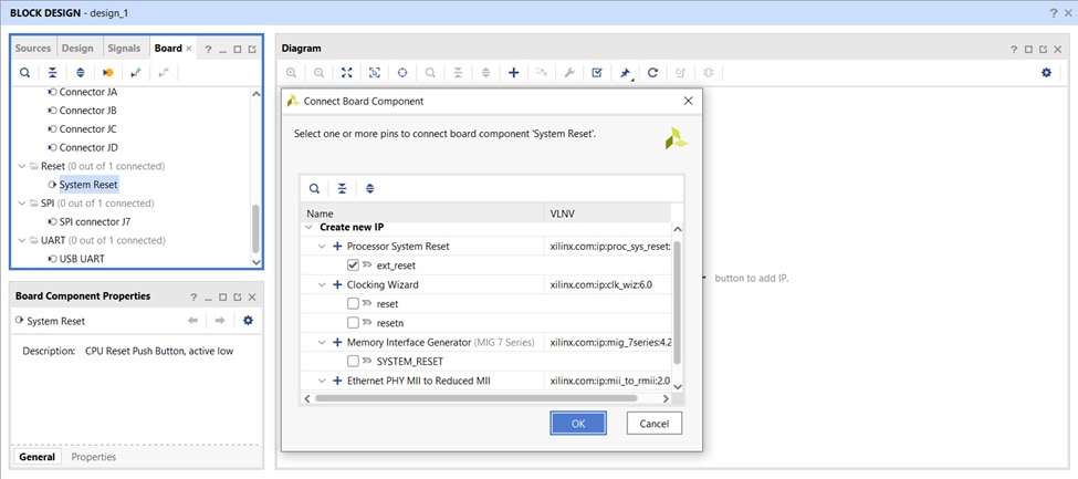
Processor System Reset IP will be added to the canvas. Double click on System Clock and Click OK.
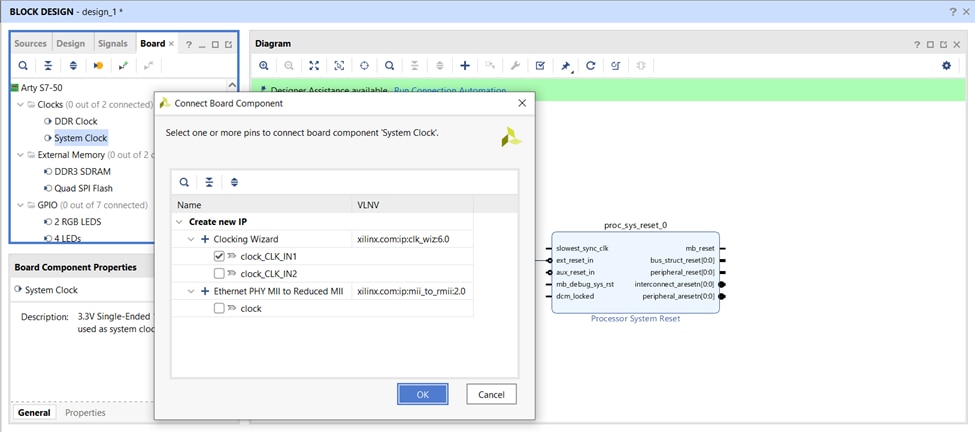
A clocking wizard which takes in a 12MHz clock and generates a 100MHz clock will be added. Double click on the clocking wizard and change reset polarity to active low, as the System Reset present on Arty is active low reset.
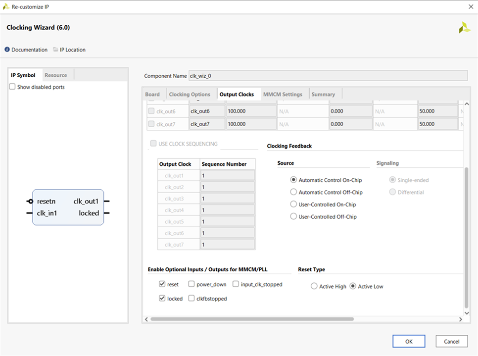
Now run connection automation to make necessary connections. Add MicroBlaze to the IP canvas.
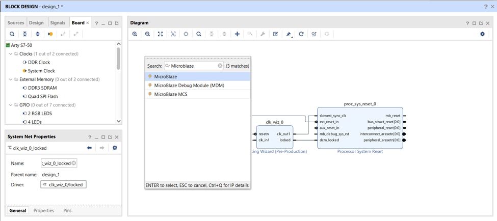
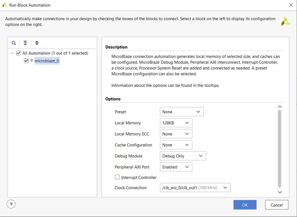
Run Block Automation to add the necessary debug module and BRAM. Make sure the following settings are selected while running automation.
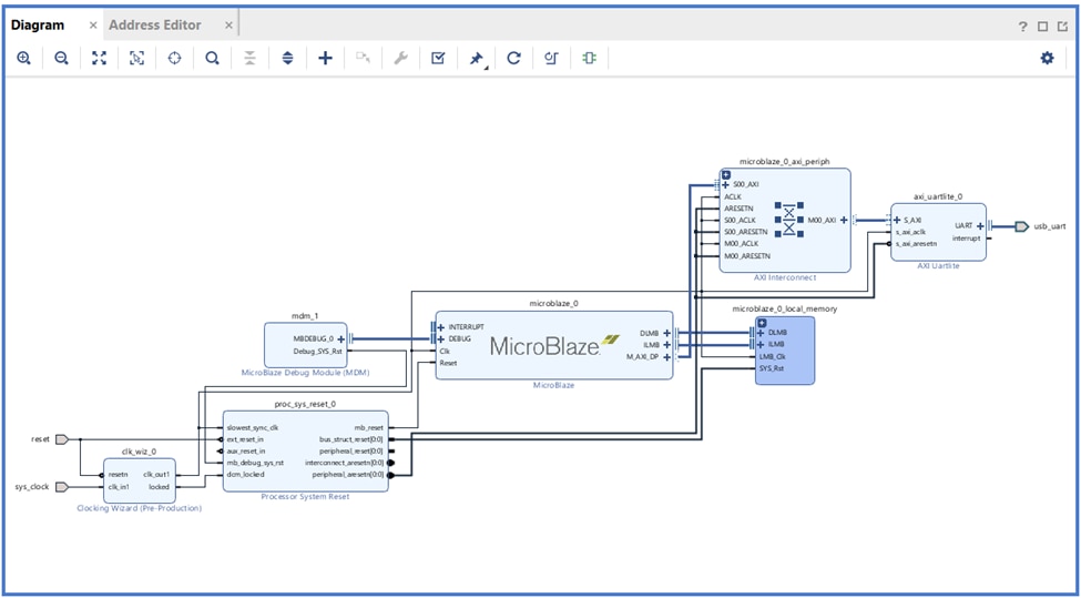
Add AXI UART Lite to IP canvas, Run Connection Automation. Now base design with MicroBlaze and UART is ready.
Arty S7-50 has a 250M Bytes (128M bits x 16) DDR in older versions of boards MT41K128M16XX-15E from Micron was used but the latest boards have PMF511816EBR from Piecemakers. Both parts have the same timing parameters, even new chips are capable of working at 1.35V.
Instead of running block automation let us configure MIG IP manually. Before proceeding make sure to download UCF File from Digilent Github. The file contains all DDR pin details and will be used later.
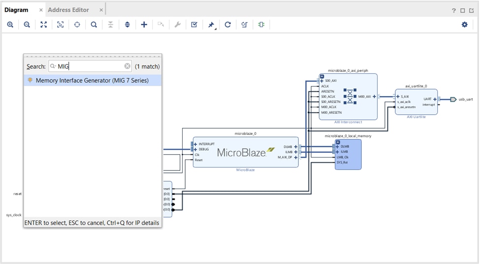
Add Memory Interface Generator to IP canvas.
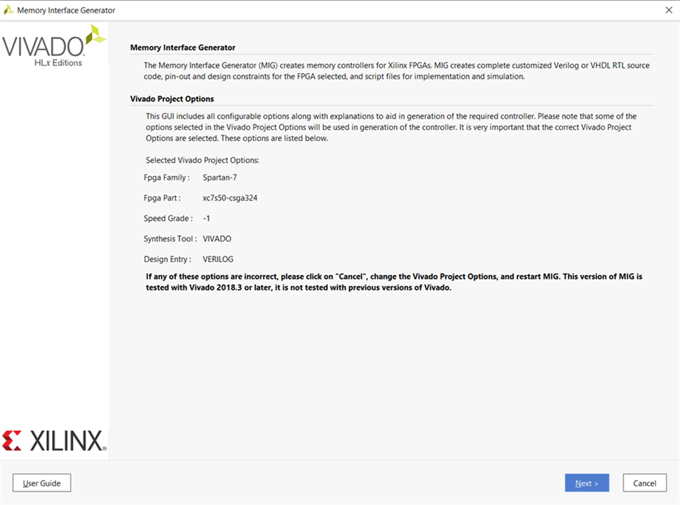
Double click on MIG IP and click Next to skip the welcome page.
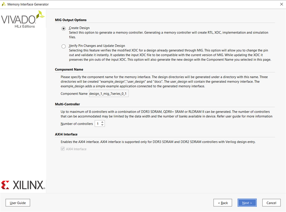
Make sure create design is selected and click on Next.
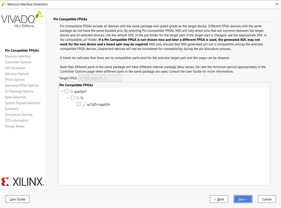
We will provide pin information in later step, so click on next instead of specifying compatible pins.
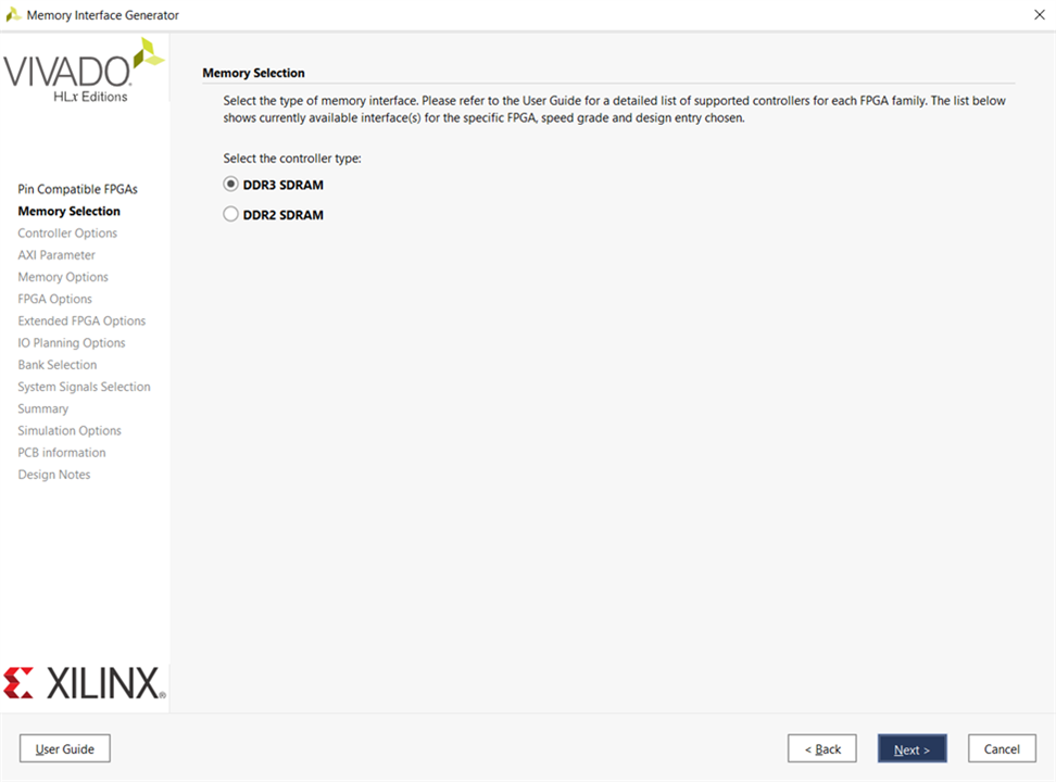
Select DDR3 SDRAM and click on Next.
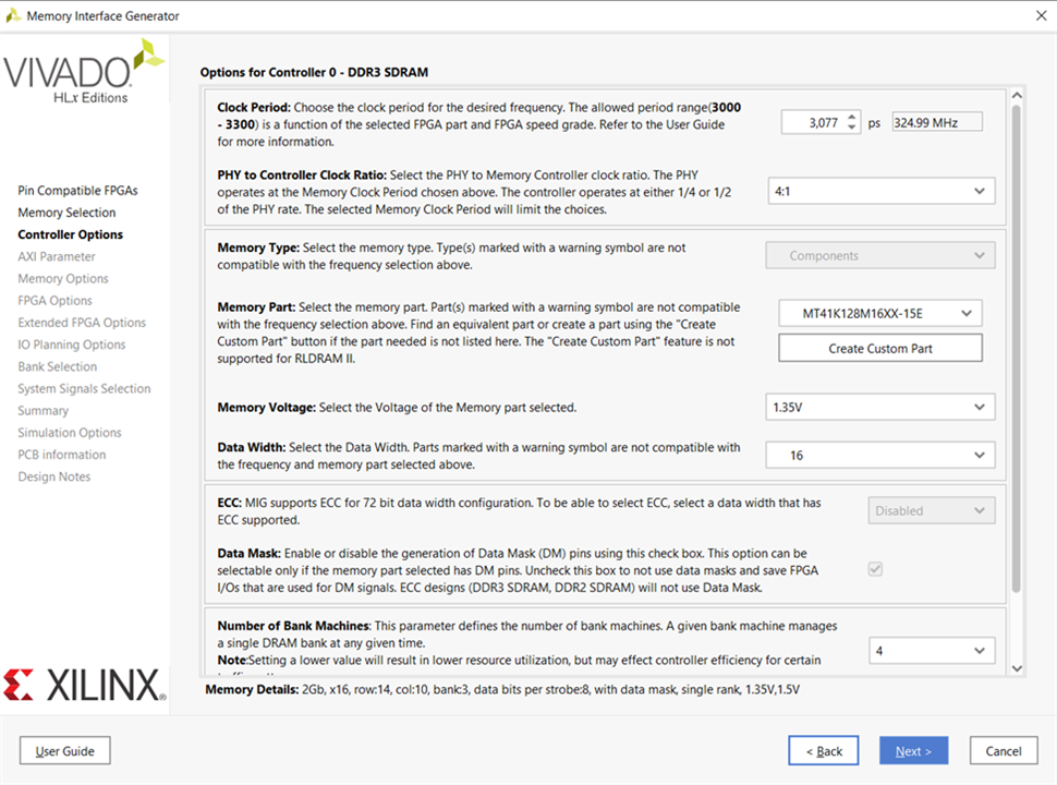
DDR will be operated at a 650Mbps data rate, with data width being 16 bits, 324.99 MHz clock must be fed. Make the following selections under the Options for Controller tab and click Next.
Clock Period: 3077 (324.99 MHz), This is the clock that will be provided as input for the DDR chip i.e., physical layer memory clock frequency.
PHY to Controller Clock Ratio: 4:1, Ration of physical layer clock frequency to user interface clock frequency.
Memory Part: MT41K128M16XX-15E, Memory part used in the board as Piecemakers part is not displayed select Micron part.
Memory Voltage 1.35 V, Voltage at which DDR chip will be operated.
Data Width: 16, Data width of the DDR chip.
ORDERING: Normal, this mode allows the memory controller to reorder commands to achieve maximum possible efficiency.
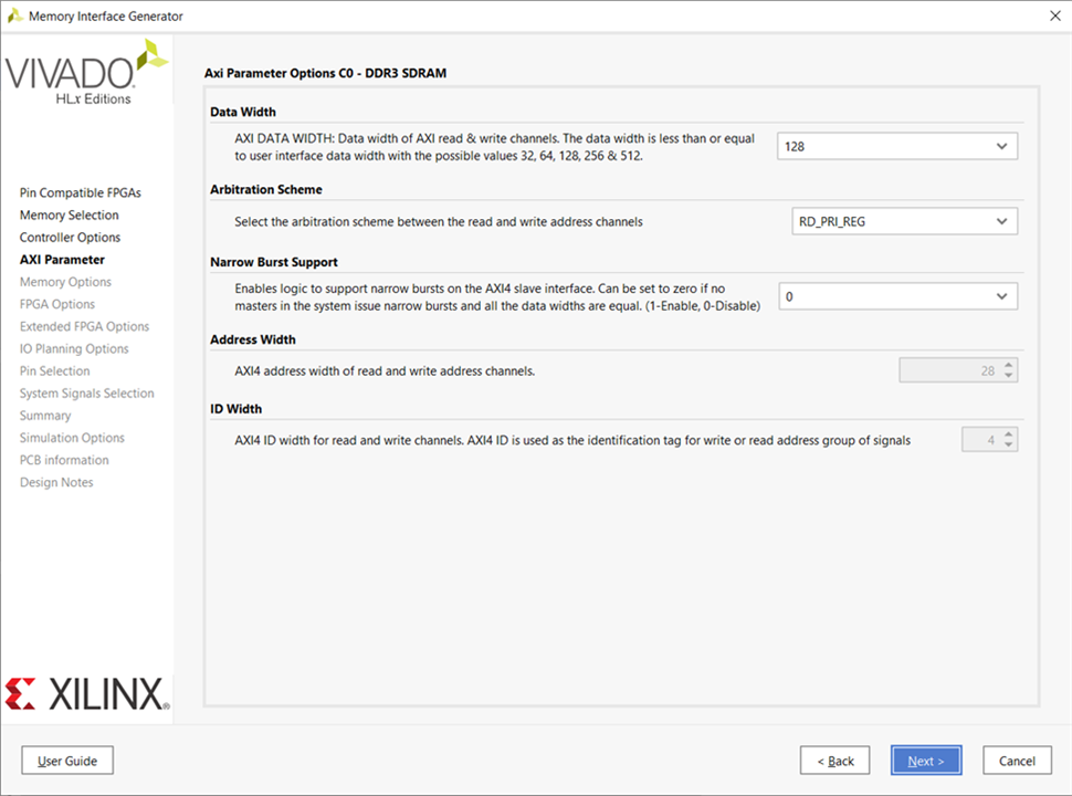
Settings under the AXI Parameter Options tab will not be changed so click on Next.
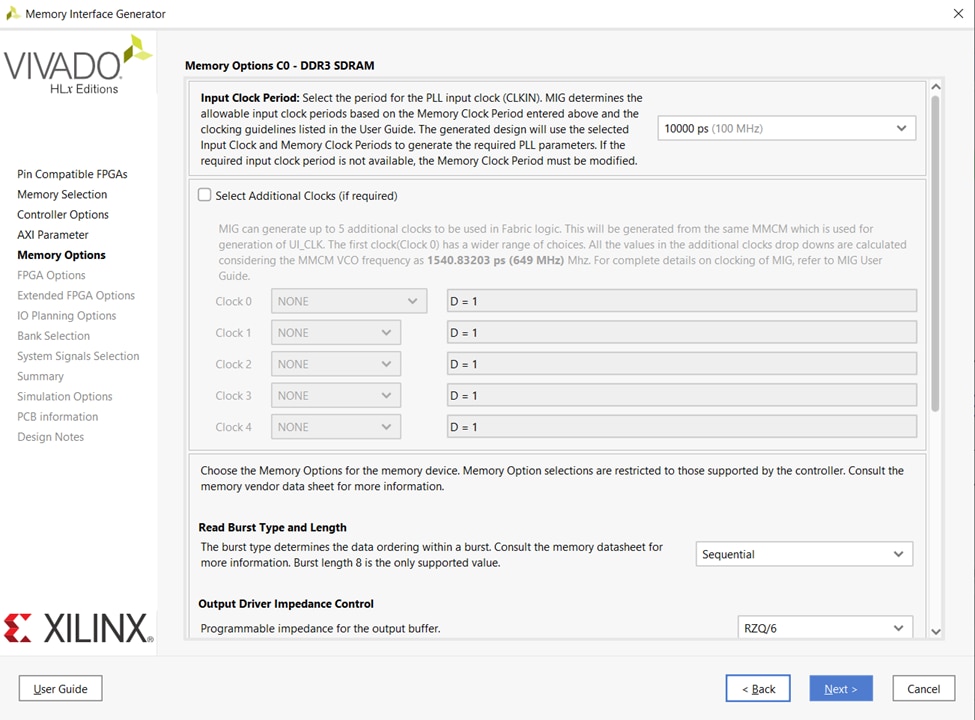
Make the following selections under the Memory Options tab and click Next.
Input Clock Period: 10000ps (100MHz), This is the reference clock provided to the MIG controller.
Output Driver Impedance Control: RZQ/6
RTT nominal – On Die Termination (ODT): RZQ/6
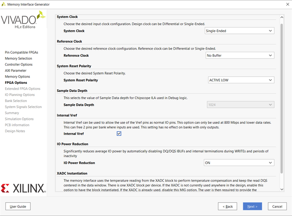
Select System Clock options as shown below click Next.
System Clock: Single Ended, Arty S7 board has a 100MHz single-ended 100MHz clock.
Reference Clock: No Buffer
System Reset Polarity: Active Low, Arty S7 has an active low system reset.
Internal Vref: Tik Mark
XADC Instantiation: Enabled
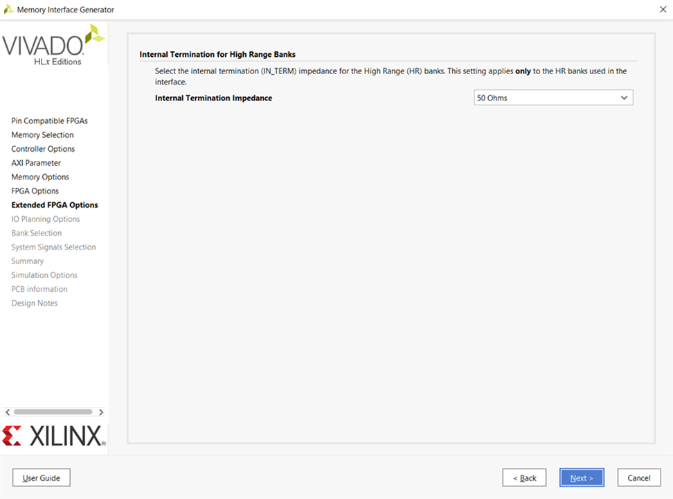
Select Internal Termination Impedance: 50 Ohms and click Next.
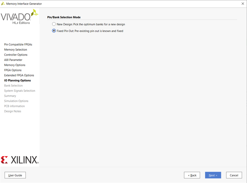
Select Fixed Pin Out: Pre-Existing pinout is known and fixed and Click Next.
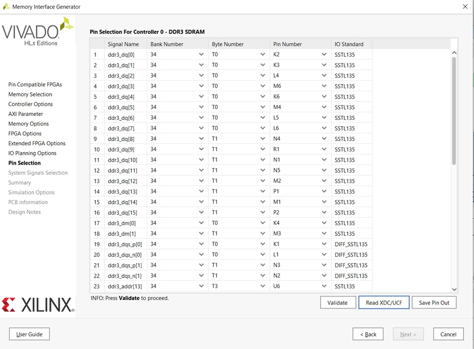
Now it’s time to import the UCF file previously downloaded select Read XDC/UCF click on Validate and click Next.
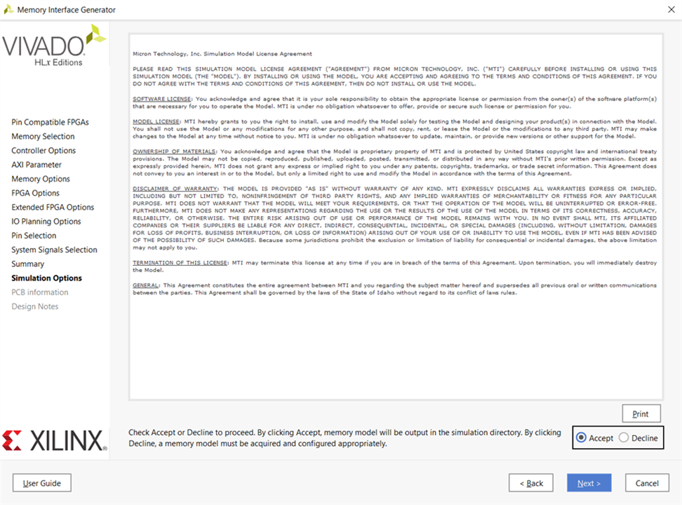
Keep on clicking Next until the Agreement window appears, accept the terms and click Next.
Click Next.
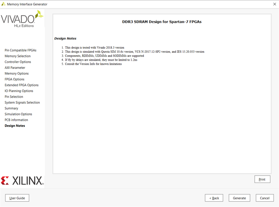
Click on Generate.
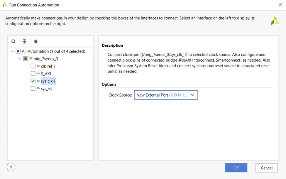
Run connection automation by selecting New External Port for DDR sys_clk_i.
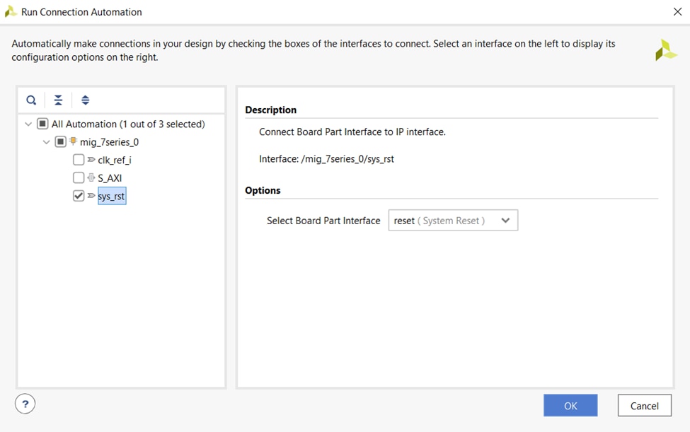
Run connection automation by selecting system reset as DDR reset.
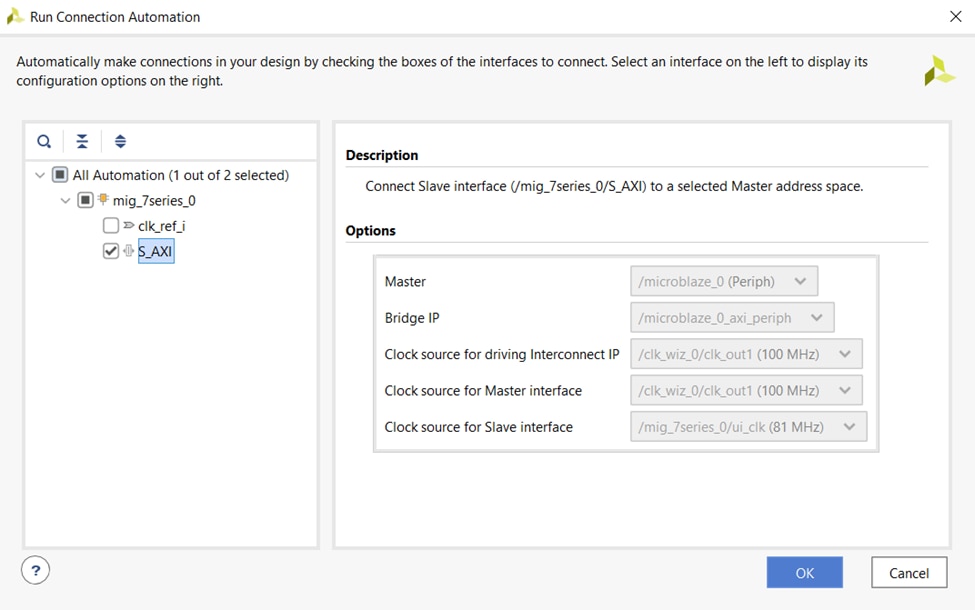
Similarly run connection automation by selecting DDR AXI Interface. AXI Interface will be running on 81.247969 MHz ui_clk generated by DDR MIG. This clock is ¼ th of physical interface clock as mentioned previously.
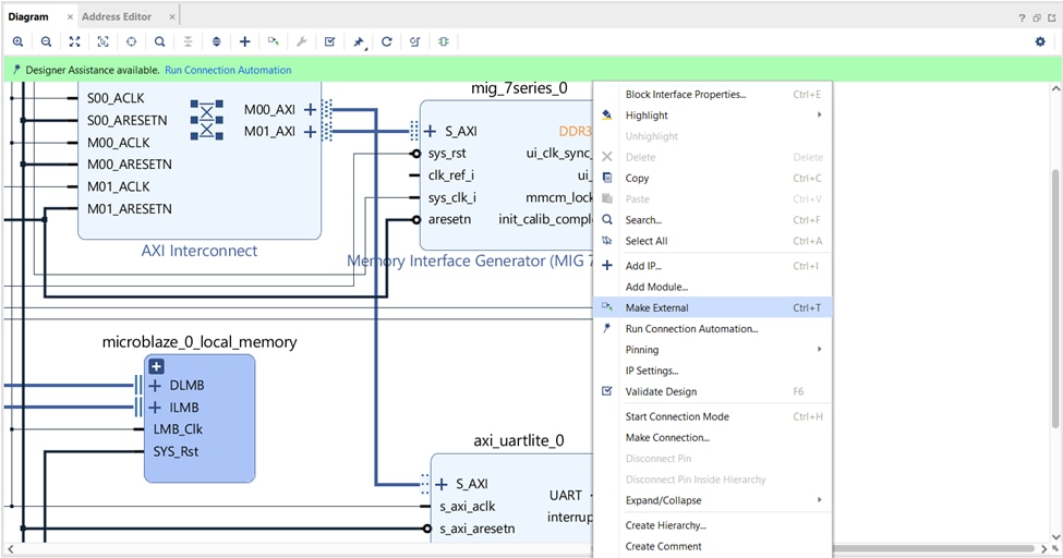
Right click on DDR port and make it external.
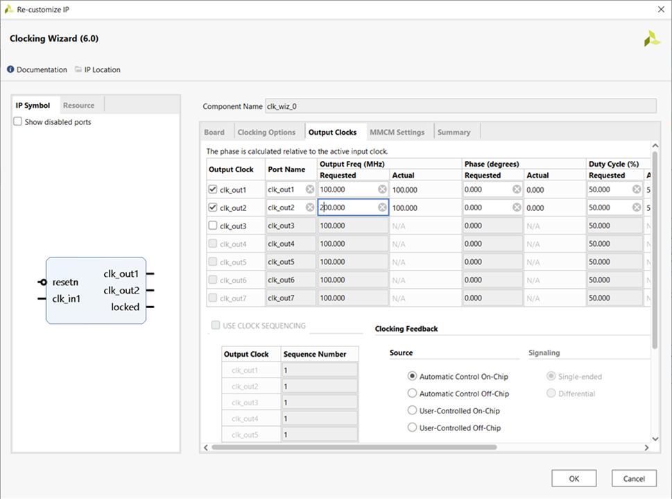
Double click on the 12MHz clocking wizard and generate secondary output clock of 200 MHz.
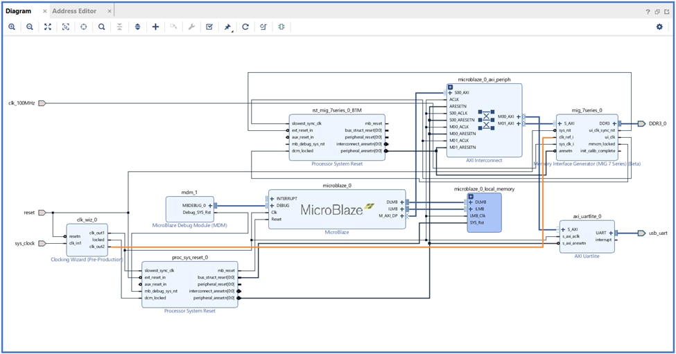
Connect 200MHz clock from clocking wizard to DDR clk_ref_i. The completed block design looks like as shown in the below image.
Validate the design and generate the bitstream. Export hardware and launch SDK.
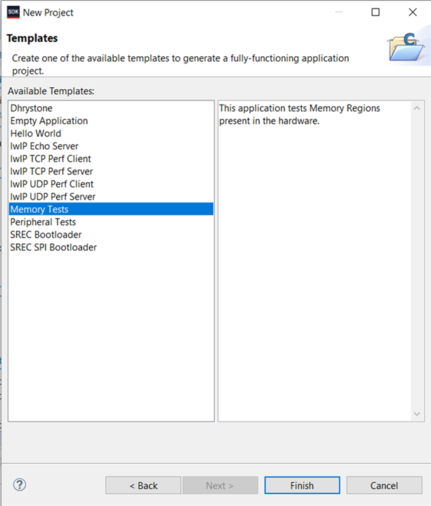
Go to File New Application Project Select the Memory Test application template and build the project.
Now program the FPGA and on successfully completing the Memory Test log as shown below will be displayed on the console.

The Tcl file of the block design is included in Github Repo.
Thank you for reading this blog, even though it is a bit lengthy hope I have covered some details on testing DDR on Arty-S7.
References


-

saadtiwana_int
-
Cancel
-
Vote Up
0
Vote Down
-
-
Sign in to reply
-
More
-
Cancel
-

hrishi98
in reply to saadtiwana_int
-
Cancel
-
Vote Up
0
Vote Down
-
-
Sign in to reply
-
More
-
Cancel
Comment-

hrishi98
in reply to saadtiwana_int
-
Cancel
-
Vote Up
0
Vote Down
-
-
Sign in to reply
-
More
-
Cancel
Children