


Introduction
This is a follow-up to Fast VHDL CORDIC Sine and Cosine Component on Lattice XP2 Device Using Diamond 3.12
I thought I had actually used the CORDIC component for real, but I was getting confused with other blogs, so now I'm going to try out the CORDIC component that I developed there with a physical FPGA board.
I'm going to utilise the Lattice XP2 Brevia 2 board, along with a Pimoroni audio CODEC, that I previously used in this blog:
Quadrature Sinewave Generator on Lattice XP2 using Brevia 2 Development Board
replacing the Taylor series calculation with the CORDIC one. There's nothing special about the XP2 - the CORDIC component should run on any FPGA that has sufficient logic elements to suffice for the resolution chosen - it's just convenient because it saves me building anything fresh for the moment.
A small complication (for me, not you) is that 2026 is going to be my 'year of Linux on the workbench', so I've moved all this to Xubuntu 22.04 LTS instead of the Win 8.1 laptop that I was previously using. I needed to do something because neither Radiant (Lattice) nor Libero (Microchip), both of which I want to start using, will run on old Windows systems. Curiously, I found Lattice Diamond the most straightforward one to get going on Linux, the others needing a bit of manual assistence to sort out missing libraries. Doing Diamond first also seemed to help with getting the licensing in place for Radiant. Something that I initially struggled with was the USB board-programming side of things, but there are scripts to put the UDEV rules in place that you run for yourself after the software installs, and then it becomes plug-and-play, just like Windows. (Tip: use the script as it does more than just put the rules file in place, and also do a full reboot of the system afterwards to bring everything into effect.) I now have the machine working happily with the Brevia 2 board, programmed from within Diamond, and a Lattice iCE40UP5K EVB, programmed from within Radiant. I was going to install iCEcube2 as well, but the Linux version is too old to be 64-bit and there are a lot of old libraries that would need to be added, including some not in the standard repositories, so I haven't for the moment.
What I'm going to do
I'm not going to do anything too complicated to start with, just compute full-amplitude, 16-bit, fixed-frequency sine and cosine with the CORDIC component and feed them as right and left samples to an I2S component that outputs to the DAC on the Pimoroni board. That fits comfortably in the 5k logic elements of the XP2 part. I've chosen 440Hz for the frequency and this time I'm working 48ksps - no particular reason, other than to try something a little different.
Here's the VHDL. Two component files, and a top-level one to tie it all together. On Lattice, you may need to use Synplify for the synthesis, rather than LSE.
------------------------------------------------------------------
--              ***** cordic_top.vhd *****                      --
-- Physical test of fast CORDIC sine and cosine component using --
-- Brevia 2 (XP2) evaluation board connected to I2S codec.      --
-- Nothing too complicated: just the CORDIC component, working  --
-- 16-bit, generating 440Hz sine and cosines, and output over   --
-- an i2s interface running at 48ksps.                          --
------------------------------------------------------------------
-- JC 13th January 2026                                         --
------------------------------------------------------------------
-- Rev    Date         Comments                                 --
-- 01     13-Jan-2026                                           --
------------------------------------------------------------------

library ieee;
use ieee.std_logic_1164.all;
use ieee.numeric_std.all;

--- top level port that connects to the device pins

entity cordic_top is port(
        --- clocks
		clk_in:			in std_logic;								--- system clock in (50 MHz oscillator)
		clk_12_288:	    in std_logic;								--- clock from my 12.288MHz crystal oscillator
		--- I2S connections - these are the connections out to the Pimoroni Pico Audio board
		mute_n:			out std_logic;								--- mute
		i2s_data:		out std_logic;								--- i2s data
		i2s_bck:		out std_logic;								--- i2s bit clock
		i2s_lrck:		inout std_logic;							--- i2s left/right word 'clock'
		--- misc control signals on Brevia 2 evaluation board that it might be good to hold at fixed levels
		spi_csn:		out std_logic;								---
		holdn:			out std_logic;								---
		sram_cen:		out std_logic;								---
		sram_oen:		out std_logic;								---
		sram_wen:		out std_logic;								---
		uart_tx:		out std_logic);							---

end cordic_top;

architecture arch_cordic_top of cordic_top is

constant sig_resol: POSITIVE := 16;             --- signal resolution (bits)
constant pha_resol: POSITIVE := 32;             --- phase resolution (bits)
signal theta: SIGNED(pha_resol-1 downto 0) := X"00000000";
signal phase_increment: SIGNED(pha_resol-1 downto 0);
signal sine: SIGNED(sig_resol-1 downto 0);
signal cosine: SIGNED(sig_resol-1 downto 0);
signal delay_i: STD_LOGIC := '0';
signal delay_o: STD_LOGIC;
signal i2s_load,i2s_load_del: STD_LOGIC;

--- declare the cordic component

component cordic is
    generic(
    	input_resol: POSITIVE;          --- input resolution
        output_resol: POSITIVE);        --- output resolution
    port(
        clk_in: in STD_LOGIC;           --- clock in
        delay_in: in STD_LOGIC;         --- delay in
        delay_out: out STD_LOGIC;       --- delay out
        theta: in SIGNED(pha_resol-1 downto 0);       --- phase in
        sine: out SIGNED(sig_resol-1 downto 0);       --- sine out
        cosine: out SIGNED(sig_resol-1 downto 0));    --- cosine out
end component;

--- declare the I2S component

component i2s is
    generic(
        input_resol: POSITIVE);                       --- input resolution
    port(
        clk_in: in STD_LOGIC;                         --- clock in
        i2s_ldata_i: in SIGNED(sig_resol-1 downto 0); --- left data in
        i2s_rdata_i: in SIGNED(sig_resol-1 downto 0); --- right data in
        i2s_bck_o: out STD_LOGIC;                     --- bit clock out
        i2s_load_o: out STD_LOGIC;                          --- load out
        i2s_lrck_o: out STD_LOGIC;                    --- left/right out
        i2s_data_o: out STD_LOGIC);                   --- data out
end component;

begin

    --- instance of cordic component

    cordic_1: component cordic
        generic map(
            input_resol => pha_resol,  --- input resolution
            output_resol => sig_resol) --- output resolution
        port map(
            clk_in => clk_12_288,      --- clock in
            delay_in => delay_i,       --- delay in
            delay_out => delay_o,      --- delay out
            theta => theta,            --- phase in
            sine => sine,              --- sine out
            cosine => cosine);         --- cosine out

    --- instance of i2s component

    i2s_1: component i2s
        generic map(
            input_resol => sig_resol)  --- input resolution
        port map(
            clk_in => clk_12_288,      --- clock in
            i2s_ldata_i => sine,       --- left data in
            i2s_rdata_i => cosine,     --- right data in
            i2s_bck_o => i2s_bck,      --- bit clock out
            i2s_load_o => i2s_load,    --- s/r load
            i2s_lrck_o => i2s_lrck,    --- left/right out
            i2s_data_o => i2s_data);   --- data out


	fpga_sinewave_stuff: process (clk_12_288)
		begin

			if (clk_12_288'event and clk_12_288 = '1') then

			    i2s_load_del <= i2s_load;

				--- phase accumulator update (immediately after load of right data)

				if ((i2s_load = '0' and i2s_load_del = '1') and i2s_lrck = '1') then
					theta <= theta + phase_increment;
				end if;

            end if;

            --- for now, I'm just going to have a constant increment for the phase
            --- at 48ksps, this should result in a 440Hz sine and cosine

            phase_increment(31 downto 0) <= b"0000_0010_0101_1000_1011_1111_0010_0110";

	    end process fpga_sinewave_stuff;

	--- Hold these device control pins at a fixed level to stop them flapping around

	spi_csn <= '1';
	holdn <= '1';
	sram_cen <= '1';
	sram_oen <= '1';
	sram_wen <= '1';
	uart_tx <= '1';
	mute_n <= '1';

end arch_cordic_top;
-------------------------------------------------------------------------------
-- cordic.vhd                                                                --
--                                                                           --
-- VHDL component to implement a fast, pipelined CORDIC sine                 --
-- and cosine calculation.                                                   --
--                                                                           --
-- Two generics specify the desired resolutions for input and output.        --
-- A delay chain sits alongside the CORDIC pipeline to relate the output to  --
-- the input.                                                                --
--                                                                           --
-- Developed for XP2 using LSE in Diamond 3.14, but fairly                   --
-- standard VHDL and no Lattice IP components so should work                 --
-- with any FPGA.                                                            --
--                                                                           --
-- Number of CORDIC stages is one more than the output resolution.           --
-- Internal data width is (output resolution * 1.25) + 3 bits.               --
--                                                                           --
-- More information at project page:                                         --
-- https://community.element14.com/technologies/fpga-group/b/blog/posts/fast-vhdl-cordic-sine-and-cosine-component-on-lattice-xp2-device-using-diamond-3-12                                                              --
-------------------------------------------------------------------------------
-- (c)2023 Jon Clift 7th April 2023                                          --
-- Free to use however you want. No warranty as to correctness.              --
-- No guarantee of fitness for any purpose. No obligation to support.        --
-------------------------------------------------------------------------------
-- Rev Date         Comments                                                 --
-- 01  31-Mar-2023  internally overflows with sin or cos close to 1          --
-- 02  07-Apr-2023  added extra bit of headroom                              --
-- 03  05-Nov-2023  added another bit to internal resolution                 --
-------------------------------------------------------------------------------

library ieee;
use ieee.std_logic_1164.all;
use ieee.numeric_std.all;
use ieee.math_real.all;

entity cordic is
    generic(
        input_resol: POSITIVE;                     --- input resolution
        output_resol: POSITIVE);                   --- output resolution
    port(
        clk_in: in STD_LOGIC;                      --- clock in
        delay_in: in STD_LOGIC;                    --- delay in
        delay_out: out STD_LOGIC;                  --- delay out
        theta: in SIGNED(input_resol-1 downto 0);       --- phase in
        sine: out SIGNED(output_resol-1 downto 0);       --- sine out
        cosine: out SIGNED(output_resol-1 downto 0));    --- cosine out
end entity cordic;

architecture arch_cordic of cordic is

--- declare the addsub component

component addsub is
    generic(
        resol: POSITIVE);                --- resolution (bits)
    port(
        clk_in: in STD_LOGIC;                 --- clock in
        a: in SIGNED(resol-1 downto 0);      --- a in
        b: in SIGNED(resol-1 downto 0);      --- b in
        d: in STD_LOGIC;                      --- d=0 add, d=1 subtract
        s: out SIGNED(resol-1 downto 0));    --- sum out
end component addsub;

constant WORD_SIZE: POSITIVE := output_resol + (output_resol/4) + 3;

type MY_STD_LOGIC_ARRAY_TYPE is array(output_resol downto 0) of STD_LOGIC;
type MY_SIGNED_ARRAY_TYPE is array(output_resol downto 0) of SIGNED(WORD_SIZE-1 downto 0);

signal temp_phase: SIGNED(WORD_SIZE downto 0);
signal start_angle: SIGNED(WORD_SIZE-1 downto 0);
signal del: MY_STD_LOGIC_ARRAY_TYPE;
signal sin, cos, angle: MY_SIGNED_ARRAY_TYPE;
signal angle_coeff: MY_SIGNED_ARRAY_TYPE;
signal sin_start_value, cos_start_value, cos_start_value_p, cos_start_value_n: SIGNED(WORD_SIZE-1 downto 0);
signal initial_dir, not_initial_dir: STD_LOGIC;
signal dir, not_dir: MY_STD_LOGIC_ARRAY_TYPE;
signal shift_cos, shift_sin: MY_SIGNED_ARRAY_TYPE;

-- function to resize fractional binary numbers (note: numeric_std RESIZE doesn't work for this because the assumed binary point is down the other end)

function fractional_resize (arg: SIGNED; new_size: NATURAL) return SIGNED is
    variable result: SIGNED(new_size-1 downto 0) := (others => '0');
    begin
        if (new_size = arg'length) then
	        result := arg;
        end if;
        if (new_size < arg'length) then
            result(new_size-1 downto 0) := arg(arg'left downto arg'length - result'length);
        end if;
        if (new_size > arg'length) then
            result(new_size-1 downto new_size-result'length) := arg(arg'left downto 0);
        end if;
        return result;
    end fractional_resize;

-- now for the component code

begin

 	temp_phase <= fractional_resize(theta,temp_phase'length);
    start_angle(start_angle'length-1 downto 0) <= temp_phase(temp_phase'length-2 downto 0);

    --- process to calculate the inverse-tangent coefficients and the overall gain (which will determine the cos start values)
	--- synthesis will understand to just calculate the values and then hardwire them into the final logic
	--- none of this floating-point calculation stuff will end up as logic in the FPGA

    calc_process: process
	    variable temp: REAL;
	    begin
        coeff_calc: for i in 0 to output_resol loop
            angle_coeff(i) <= to_signed(integer(round((2.0**real(WORD_SIZE-1)) * (arctan(2.0**(-1.0 * real(i))) / math_pi_over_2))),WORD_SIZE);
        end loop coeff_calc;
		temp := 1.0;
        gain_calc: for i in 0 to output_resol loop
            temp := temp * sqrt(1.0 + (2.0**(-2.0 * real(i))));
        end loop gain_calc;
		temp := (0.5 - (2.0**(-1.0 * real(output_resol-1))/2.0)) / temp;   --- adjustment to stop overflow (not very scientific!)
        cos_start_value_p <= to_signed(integer(trunc((2.0**real(WORD_SIZE-1)) * temp)),WORD_SIZE);
        cos_start_value_n <= to_signed(integer(trunc(-1.0 * (2.0**real(WORD_SIZE-1)) * temp)),WORD_SIZE);
		sin_start_value <= (others => '0');
		wait;
    end process calc_process;

	--- now generate the logic for the cordic stages

    cordic_stages: for k in 0 to output_resol generate

    begin
        first_stage: if(k = 0) generate
        begin
            first_stage_process: process (clk_in,theta)
            begin
                if (clk_in'event and clk_in='1') then
                    del(0) <= delay_in;
				end if;
			end process;
			cos_start_value <= cos_start_value_p when ((theta(theta'length-1) xor theta(theta'length-2)) = '0') else cos_start_value_n;
			initial_dir <= theta(theta'length-2);
			not_initial_dir <= not theta(theta'length-2);
            addsub_1: component addsub generic map(resol => WORD_SIZE) port map(clk_in => clk_in, a => sin_start_value, b => cos_start_value, d => initial_dir, s => sin(0));
            addsub_2: component addsub generic map(resol => WORD_SIZE) port map(clk_in => clk_in, a => cos_start_value, b => sin_start_value, d => not_initial_dir, s => cos(0));
            addsub_3: component addsub generic map(resol => WORD_SIZE) port map(clk_in => clk_in, a => start_angle, b => angle_coeff(0), d => not_initial_dir, s => angle(0));
		end generate first_stage;

		other_stages: if(k /= 0) generate
		begin
            other_stages_process: process (clk_in)
            begin
                if (clk_in'event and clk_in='1') then
                    del(k) <= del(k-1);
				end if;
			end process;
    		shift_cos(k) <= shift_right(cos(k-1),k);
	    	shift_sin(k) <= shift_right(sin(k-1),k);
			dir(k) <= angle(k-1)(WORD_SIZE-1);
			not_dir(k) <= not angle(k-1)(WORD_SIZE-1);
            addsub_4: component addsub generic map(resol => WORD_SIZE) port map(clk_in => clk_in, a => sin(k-1), b => shift_cos(k), d => dir(k), s => sin(k));
            addsub_5: component addsub generic map(resol => WORD_SIZE) port map(clk_in => clk_in, a => cos(k-1), b => shift_sin(k), d => not_dir(k), s => cos(k));
            addsub_6: component addsub generic map(resol => WORD_SIZE) port map(clk_in => clk_in, a => angle(k-1), b => angle_coeff(k), d => not_dir(k), s => angle(k));
		end generate other_stages;

    end generate cordic_stages;

    --- connect outputs to signals in design
	--- sine and cosine results need resizing (this is crude truncation)
	--- also need to exclude the additional overhead bit

    delay_out <= del(output_resol);
    sine(output_resol-1) <= sin(output_resol)(WORD_SIZE-1);
    sine(output_resol-2 downto 0) <= sin(output_resol)(WORD_SIZE-3 downto (WORD_SIZE-output_resol)-1);
    cosine(output_resol-1) <= cos(output_resol)(WORD_SIZE-1);
    cosine(output_resol-2 downto 0) <= cos(output_resol)(WORD_SIZE-3 downto (WORD_SIZE-output_resol)-1);

end arch_cordic;

-------------------------------------------------------------------------------
-- addsub                                                                    --
--                                                                           --
-- VHDL component to implement 2's complement add or subtract                --
-- no output carry                                                           --
-- registered output for the pipeline                                        --
-------------------------------------------------------------------------------
library ieee;
use ieee.std_logic_1164.all;
use ieee.numeric_std.all;

entity addsub is
    generic(
        resol: POSITIVE);             --- desired resolution (bits)
    port(
        clk_in: in STD_LOGIC;                 --- clock in
        a: in SIGNED(resol-1 downto 0);      --- a in
        b: in SIGNED(resol-1 downto 0);      --- b in
        d: in STD_LOGIC;                      --- d=0 add, d=1 subtract
        s: out SIGNED(resol-1 downto 0));    --- sum out
end entity addsub;

-- this version uses numeric_std addition and subtraction.
-- synthesis seems to build both and place a mux on output to select which result we want.
-- not necessarily good for space
-- but synthesis knows how to use fast carry-chain logic to good advantage

architecture arch_addsub of addsub is

signal result: SIGNED(resol-1 downto 0):= (others => '0');

begin

    add_sub_process: process (clk_in)
    begin
        if (rising_edge(clk_in)) then
	        if(d = '0') then
                result <= a + b;
            else
                result <= a - b;
            end if;
	    end if;
    end process;

    s <= result;

end arch_addsub;
-------------------------------------------------------------------------------
-- i2s.vhd                                                                   --
--                                                                           --
-- VHDL component to implement an I2S digital sound interface                --
--                                                                           --
-- Developed for XP2 using LSE in Diamond 3.12                               --
-- This is for use with a 12.288MHz input clock and 48ksps sampling          --
--                                                                           --
-------------------------------------------------------------------------------
-- (c)2023 Jon Clift 5th November 2023                                       --
-- Free to use however you want. No warranty as to correctness.              --
-- No guarantee of fitness for any purpose. No obligation to support.        --
-------------------------------------------------------------------------------
-- Rev Date         Comments                                                 --
-- 01  05-Nov-2023                                                           --
-- 02  13-Jan-2026  Added i2s_load_o to port                                 --
-------------------------------------------------------------------------------

library ieee;
use ieee.std_logic_1164.all;
use ieee.numeric_std.all;

entity i2s is
    generic(
        input_resol: POSITIVE);                            --- input resolution
    port(
        clk_in: in STD_LOGIC;                              --- clock in
        i2s_ldata_i: in SIGNED(input_resol-1 downto 0);   --- left data in
        i2s_rdata_i: in SIGNED(input_resol-1 downto 0);   --- right data in
        i2s_bck_o: out STD_LOGIC;                           --- bit clock out
        i2s_load_o: out STD_LOGIC;                          --- load out
        i2s_lrck_o: out STD_LOGIC;                          --- left/right out
        i2s_data_o: out STD_LOGIC);                        --- data out
end entity i2s;

architecture arch_i2s of i2s is

signal prescale_count: UNSIGNED(1 downto 0) := b"00";
signal i2s_bit_count: UNSIGNED(5 downto 0) := b"000000";
signal i2s_sr: SIGNED(31 downto 0);
signal i2s_bit_en_falling,i2s_load: STD_LOGIC;

begin

	i2s_stuff: process (clk_in)
		begin

			if (clk_in'event and clk_in = '1') then

				--- prescaler divides by 4 to give I2S bit rate of 3.072M (64 x sample rate)
				--- prescale_count(1) will be the I2S bck

				prescale_count(1 downto 0) <= prescale_count(1 downto 0) + 1;	--- count up

				--- generate an enable that precedes the I2S bit clock falling edge for one clock cycle

				if (prescale_count = "10") then				--- is this count 2?
					i2s_bit_en_falling <= '1';					--- yes: high on next cycle (count 3)
				else
					i2s_bit_en_falling <= '0';
				end if;

				--- bit_count now counts off the 64 bit times in the I2S cycle
				--- that's 2 x 32-bit samples for dual-channel 48ksps
				--- i2s_bit-count(5) will be the I2S lrck

				if (i2s_bit_en_falling = '1') then					--- qualify with the enable
					i2s_bit_count(5 downto 0) <= i2s_bit_count(5 downto 0) + 1;	--- count up
				end if;

				--- my shift register for the data is 32 bits
				--- this load signal then has to occur twice during the I2S cycle
				--- once for the left sample and once for the right

				if (i2s_bit_en_falling = '1') then					--- qualify with the enable
					if (i2s_bit_count(4 downto 0) = b"11111") then
						i2s_load <= '1';
					else
						i2s_load <= '0';
					end if;
				end if;

				--- i2s output shift register
				--- for any bit cycle, either loads a new sample or does a shift
				--- the sample can be either left or right value, the multiplexing is bundled into the code

				if (i2s_bit_en_falling = '1') then									--- qualify with the bit enable
					if (i2s_load = '1') then										--- load?
						if (i2s_bit_count(5) = '0') then							--- use lrclk to select what to load...
							i2s_sr(31 downto 32-input_resol) <= i2s_ldata_i(input_resol-1 downto 0);		    ---   left data
							i2s_sr(31-input_resol downto 0) <= (others => '0');					---   pad with zeroes
						else														--- or
							i2s_sr(31 downto 32-input_resol) <= i2s_rdata_i(input_resol-1 downto 0);		    ---   right data
							i2s_sr(31-input_resol downto 0) <= (others => '0');					---   pad with zeroes
						end if;
					else															--- else
						i2s_sr(31 downto 1) <= i2s_sr(30 downto 0);	            ---   shift out the register contents
						i2s_sr(0) <= '0';	            							---   lsb
					end if;
				end if;

			end if;

			--- connect the external control signals to signals in the design

			i2s_bck_o <= prescale_count(1);		--- i2s bit clock
			i2s_lrck_o <= i2s_bit_count(5);		--- i2s left/right word clock
			i2s_data_o <= i2s_sr(31);				--- i2s data
			i2s_load_o <= i2s_load;				--- i2s load

		end process i2s_stuff;


end arch_i2s;
Results
Here are the output waveforms displayed on an oscilloscope.
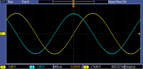
This is the line output from the Pimoroni board. To achieve those high levels, the DAC part has capacitor switchers to generate the voltage rails.
This is the FFT of one of the waveforms.
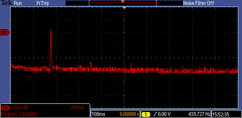
It's not all that pure - there are obvious traces of the harmonics poking up from the noise floor of the 8-bit scope sampling if you work across from the fundamental at 440Hz. This is the same thing I saw when the waves were generated with a Taylor series, so it strongly suggests that the problem lies with the output DAC and not the calculation.
Also, the frequency is a little bit off. It could well be that I calculated the phase increment wrongly, but I think that it's actually the fault of the 12.288MHz xtal oscillator. So I'll need to have a look at that.
Usage is about 30% of the '5K' XP2 device on the Brevia 2 board.

Miscellaneous Notes
The Taylor series converges more quickly, but needs multipliers.
The CORDIC needs a stage for each bit of resolution, but only needs modest amounts of logic (add/subtract of constants).
With sensible pipelining they'll both run very fast, but, with increasing resolution, carry chains become an issue, and the Taylor will slow once multiple multipliers need to be combined.
Both need embedded constants - for the CORDIC I did that 'automagically' with the VHDL math library, but be aware that VHDL only stipulates that maths be done to whatever the underlying platform can manage (presumably 64-bit floats from the FPU on a PC?), so for very high resolutions you'd probably need a different way to derive those constants.
The Taylor series is an approximation that's accurate around zero and steadily becomes less accurate as you move away.
The CORDIC is a form of successive approximation, but because the underlying algorithm is essentially a rotating vector, will only work over half a turn (but is easy to extend to a full turn by having two choices as to the start point of the vector). Depending what your use of the CORDIC is, it can make sense to scale everything so that the phase is a binary fraction (of a complete turn). I did that here to simplify the phase handling for waveform generation. If you want it for calculation purposes, you'd need to remove the normalisation I did and take it back to radians.)
Potentially, both can be extended to cover a wider range of trig functions and not just the sine and cosine.
What Next?
Although I'm tempted to develop this further on the XP2 board, I'm actually going to quickly port it to an iCE40UP5K evaluation board. That's because I want to do a simple 'roadtest' of that board and I also want to get familiar with using Radiant. To make that one a little bit more interesting, though, I'm going to rework the output to SPDIF rather than I2C. More 'trailing edge' than 'leading edge', as everyone now seems to be abandoning it in favour of USB, but there we go.


