


Introduction
This is still work in progress - I've only reached the simulation phase and haven't tried it on a device yet - but I thought it might be of some interest.
Back when I did my 'Making Waves' blogs [1], I implemented a fast, unrolled, pipelined CORDIC sine and cosine. That was fixed in resolution and, even though the resolution was low, the code was already quite cumbersome as there was a lot of needless repetition describing each stage of the pipeline. Now that I have a proper CODEC connected to my XP2 dev board it seemed like a good point to rework the VHDL, in a more generic form, so that it could be used as a component, with the user choosing the resolution and with the stages of the pipeline generated iteratively. It's also an opportunity for me to move into the 21st century and get to grips with using numeric_std. I'm going to try and work just with standard VHDL (ie inference, with no Lattice IP components) to make it as portable as possible.
Although I've called it a CORDIC component, in this form it's specific to generating the sine/cosine pair. The components that are offered by manufacturers as IP seem to be more general. It wouldn't take too much work to adapt what I've done to other CORDIC uses.
One minor complication with all this might be my use of the ieee math_real library, though it's probably much less of a problem now than it once would have been. I'm not using it for synthesis, it's just in there for calculating the trig constants, but it's possible that your synthesis may not like it. In that case, you'd need to work out the coefficients some other way and include them as an array of values.
The CORDIC Component
Here's the code of the component.
I've chosen to have two generics, one to specify the resolution of the input and one the resolution of the output.
----------------------------------------------------------------------------------
-- cordic.vhd 																	--
--																				--
-- VHDL component to implement a fast, pipelined CORDIC sine					--
-- and cosine calculation.														--
--																				--
-- Two generics specify the desired resolutions for input and output.			--
-- A delay chain sits alongside the CORDIC pipeline to relate the output to		--
-- the input. You'd need something equivalent somewhere in your design and		--
-- this way it can adjust to the number of stages within the component			--
-- without the user needing knowledge of the internals. 						--
-- 																				--
-- Developed for XP2 using LSE in Diamond 3.12, but fairly						--
-- standard VHDL and no Lattice IP components so should work					--
-- with any FPGA.																--
--																				--
-- When I've got it working, I'll try for some typical area figures on the		--
-- various FPGAs I have to hand as a guide. Speed will naturally tend to		--
-- slow with higher resolution as a consequence of the longer carry chains.		--
--																				--
-- Number of CORDIC stages is one more than the output resolution.				--
-- Internal data width is (output resolution * 1.25) + 2 bits.					--
--																				--
-- Those two came from a paper on the subject, not my personal experience.		--
--																				--
-- More information at project page:											--
-- element14.com																--
----------------------------------------------------------------------------------
-- (c)2023 Jon Clift 31st March 2023											--
-- Free to use how you want. No warranty as to correctness,						--
-- no guarantee of fitness for any purpose, nor any obligation to support.		--
----------------------------------------------------------------------------------
-- Rev Date        Comments														--
-- 01  31-Mar-2023																--
----------------------------------------------------------------------------------

library ieee;
use ieee.std_logic_1164.all;
use ieee.numeric_std.all;
use ieee.math_real.all;

entity cordic is
	generic(
		input_resol: POSITIVE; --- input resolution
		output_resol: POSITIVE); --- output resolution
	port(
		clk_in: in STD_LOGIC; --- clock in
		delay_in: in STD_LOGIC; --- delay in
		delay_out: out STD_LOGIC; --- delay out
		theta: in SIGNED(input_resol-1 downto 0); --- phase in
		sine: out SIGNED(output_resol-1 downto 0); --- sine out
		cosine: out SIGNED(output_resol-1 downto 0)); --- cosine out
	end entity cordic;

architecture arch_cordic of cordic is

--- declare the addsub component

component addsub is
	generic(
		resol: POSITIVE); --- resolution (bits)
	port(
		clk_in: in STD_LOGIC; --- clock in
		a: in SIGNED(resol-1 downto 0); --- a in
		b: in SIGNED(resol-1 downto 0); --- b in
		d: in STD_LOGIC; --- d=0 add, d=1 subtract
		s: out SIGNED(resol-1 downto 0)); --- sum out
	end component addsub;

constant WORD_SIZE: POSITIVE := output_resol + (output_resol/4) + 2;

type MY_STD_LOGIC_ARRAY_TYPE is array(output_resol downto 0) of STD_LOGIC;
type MY_SIGNED_ARRAY_TYPE is array(output_resol downto 0) of SIGNED(WORD_SIZE-1 downto 0);

signal temp_phase: SIGNED(WORD_SIZE downto 0);
signal start_angle: SIGNED(WORD_SIZE-1 downto 0);
signal del: MY_STD_LOGIC_ARRAY_TYPE;
signal sin, cos, angle: MY_SIGNED_ARRAY_TYPE;
signal angle_coeff: MY_SIGNED_ARRAY_TYPE;
signal sin_start_value, cos_start_value, cos_start_value_p, cos_start_value_n: SIGNED(WORD_SIZE-1 downto 0);
signal initial_dir, not_initial_dir: STD_LOGIC;
signal dir, not_dir: MY_STD_LOGIC_ARRAY_TYPE;
signal shift_cos, shift_sin: MY_SIGNED_ARRAY_TYPE;

-- function to resize fractional binary numbers (note: numeric_std RESIZE doesn't work for this because the assumed binary point is down the other end)

function fractional_resize (arg: SIGNED; new_size: NATURAL) return SIGNED is
	variable result: SIGNED(new_size-1 downto 0) := (others => '0');
	begin
		if (new_size = arg'length) then
			result := arg;
		end if;
		if (new_size < arg'length) then
			result(new_size-1 downto 0) := arg(arg'left downto arg'length - result'length);
		end if;
		if (new_size > arg'length) then
			result(new_size-1 downto new_size-result'length) := arg(arg'left downto 0);
		end if;
	return result;
end fractional_resize;

-- now for the component code

begin

temp_phase <= fractional_resize(theta,temp_phase'length);
start_angle(start_angle'length-1 downto 0) <= temp_phase(temp_phase'length-2 downto 0);

--- process to calculate the inverse-tangent coefficients and the overall gain (which will determine the cos start values)
--- synthesis will understand to just calculate the values and then hardwire them into the final logic
--- none of this floating-point calculation stuff will end up as logic in the FPGA

calc_process: process
	variable temp: REAL;
	begin
		coeff_calc: for i in 0 to output_resol loop
			angle_coeff(i) <= to_signed(integer(round((2.0**real(WORD_SIZE-1)) * (arctan(2.0**(-1.0 * real(i))) / math_pi_over_2))),WORD_SIZE);
		end loop coeff_calc;
		temp := 1.0;
		gain_calc: for i in 0 to output_resol loop
			temp := temp * sqrt(1.0 + (2.0**(-2.0 * real(i))));
		end loop gain_calc;
		temp := 0.5 / temp; --- temporary: limit to half amplitude
		cos_start_value_p <= to_signed(integer(round((2.0**real(WORD_SIZE-1)) * temp)),WORD_SIZE);
		cos_start_value_n <= to_signed(integer(round(-1.0 * (2.0**real(WORD_SIZE-1)) * temp)),WORD_SIZE);
		sin_start_value <= (others => '0');
		wait;
	end process calc_process;

--- now generate the logic for the cordic stages

	cordic_stages: for k in 0 to output_resol generate
	begin

	first_stage: if(k = 0) generate
		begin
			first_stage_process: process (clk_in,theta)
				begin
					if (clk_in'event and clk_in='1') then
						del(0) <= delay_in;
					end if;
				end process;
			cos_start_value <= cos_start_value_p when ((theta(theta'length-1) xor theta(theta'length-2)) = '0') else cos_start_value_n;
			initial_dir <= theta(theta'length-2);
			not_initial_dir <= not theta(theta'length-2);
			addsub_1: component addsub generic map(resol => WORD_SIZE) port map(clk_in => clk_in, a => sin_start_value, b => cos_start_value, d => initial_dir, s => sin(0));
			addsub_2: component addsub generic map(resol => WORD_SIZE) port map(clk_in => clk_in, a => cos_start_value, b => sin_start_value, d => not_initial_dir, s => cos(0));
			addsub_3: component addsub generic map(resol => WORD_SIZE) port map(clk_in => clk_in, a => start_angle, b => angle_coeff(0), d => not_initial_dir, s => angle(0));
		end generate first_stage;

	other_stages: if(k /= 0) generate
		begin
			other_stages_process: process (clk_in)
				begin
					if (clk_in'event and clk_in='1') then
						del(k) <= del(k-1);
					end if;
				end process;
			shift_cos(k) <= shift_right(cos(k-1),k);
			shift_sin(k) <= shift_right(sin(k-1),k);
			dir(k) <= angle(k-1)(WORD_SIZE-1);
			not_dir(k) <= not angle(k-1)(WORD_SIZE-1);
			addsub_4: component addsub generic map(resol => WORD_SIZE) port map(clk_in => clk_in, a => sin(k-1), b => shift_cos(k), d => dir(k), s => sin(k));
			addsub_5: component addsub generic map(resol => WORD_SIZE) port map(clk_in => clk_in, a => cos(k-1), b => shift_sin(k), d => not_dir(k), s => cos(k));
			addsub_6: component addsub generic map(resol => WORD_SIZE) port map(clk_in => clk_in, a => angle(k-1), b => angle_coeff(k), d => not_dir(k), s => angle(k));
		end generate other_stages;

	end generate cordic_stages;

--- connect outputs to signals in design
--- sine and cosine results need resizing
--- this is crude truncation

	delay_out <= del(output_resol);
	sine <= sin(output_resol)(WORD_SIZE-1 downto WORD_SIZE-output_resol);
	cosine <= cos(output_resol)(WORD_SIZE-1 downto WORD_SIZE-output_resol);

end arch_cordic;

-------------------------------------------------------------------------------
-- addsub --
-- --
-- VHDL component to implement 2's complement add or subtract --
-- no output carry --
-------------------------------------------------------------------------------
library ieee;
use ieee.std_logic_1164.all;
use ieee.numeric_std.all;

entity addsub is
	generic(
		resol: POSITIVE); --- desired resolution (bits)
	port(
		clk_in: in STD_LOGIC; --- clock in
		a: in SIGNED(resol-1 downto 0); --- a in
		b: in SIGNED(resol-1 downto 0); --- b in
		d: in STD_LOGIC; --- d=0 add, d=1 subtract
		s: out SIGNED(resol-1 downto 0)); --- sum out
	end entity addsub;

-- this version uses numeric_std addition and subtraction.
-- synthesis seems to build both and place a mux on output to select which result we want.
-- not necessarily good for space
-- but synthesis knows how to use fast carry-chain logic to good advantage

architecture arch_addsub of addsub is

signal result: SIGNED(resol-1 downto 0):= (others => '0');

begin

	add_sub_process: process (clk_in)
		begin
			if (rising_edge(clk_in)) then
				if(d = '0') then
					result <= a + b;
				else
					result <= a - b;
				end if;
			end if;
		end process;

--- connect outputs to signals in design

s <= result;

end arch_addsub;

-- this version was me trying to build a combined adder/subtractor.
-- problem with it was that synthesis doesn't recognise to use the fast carry logic

--architecture arch_addsub of addsub is

--signal result: SIGNED(resol-1 downto 0):= (others => '0');
--signal carry: STD_LOGIC_VECTOR(resol-1 downto 0):= (others => '0');

--begin

--addsub_bits: for k in 0 to resol-1 generate

--begin
--first_bit: if(k = 0) generate
--begin
--first_stage_process: process (clk_in)
--begin
--if (rising_edge(clk_in)) then
--result(k) <= (not a(k) and b(k) and not d) or
--(a(k) and not b(k) and not d) or
--(not a(k) and b(k) and d) or
--(a(k) and not b(k) and d);
--end if;
--end process;
--carry(k) <= (a(k) and b(k) and not d) or
--(not a(k) and not b(k) and d) or
--(a(k) and not b(k) and d) or
--(a(k) and b(k) and d);
--end generate first_bit;

--other_bits: if(k /= 0) generate
--begin
--other_bits: process (clk_in)
--begin
--if (rising_edge(clk_in)) then
--result(k) <= (not a(k) and b(k) and not carry(k-1) and not d) or
--(a(k) and not b(k) and not carry(k-1) and not d) or
--(not a(k) and not b(k) and carry(k-1) and not d) or
--(a(k) and b(k) and carry(k-1) and not d) or
--(not a(k) and not b(k) and not carry(k-1) and d) or
--(a(k) and b(k) and not carry(k-1) and d) or
--(not a(k) and b(k) and carry(k-1) and d) or
--(a(k) and not b(k) and carry(k-1) and d);
--end if;
--end process;
--carry(k) <= (a(k) and b(k) and not carry(k-1) and not d) or
--(not a(k) and b(k) and carry(k-1) and not d) or
--(a(k) and not b(k) and carry(k-1) and not d) or
--(a(k) and b(k) and carry(k-1) and not d) or
--(a(k) and not b(k) and not carry(k-1) and d) or
--(not a(k) and not b(k) and carry(k-1) and d) or
--(a(k) and not b(k) and carry(k-1) and d) or
--(a(k) and b(k) and carry(k-1) and d);
--end generate other_bits;

--end generate addsub_bits;

-- connect outputs to signals in design

--s <= result;

--end arch_addsub;
Because of the pipeline it's synchronous, so there's an input clock. The input that the sine and cosine are calculated from is theta, the phase of the waveform. There's also a delay chain, with an input and an output. You'd need something equivalent, somewhere in your overall design, but by incorporating it into the component it can be generated under the control of the generic, alongside the pipeline, without the user needing to know the detail of the inner working of the component.
As we want to choose the resolution (at the time of synthesis) with the generics, the width of some of the signal vectors and the size of some of the arrays also need to change. You can see how I've done that using the generic variables.
Each stage of the pipeline has outputs for the angle, sine, and cosine. To make that manageable, I've created each of them as an array of type SIGNED. The array index is the stage that the value corresponds to.
The stages of the CORDIC pipeline are generated one at a time in the cordic_stages loop. The first stage has to be different to the others because its inputs come from the required phase theta and the starting values for sin and cos whereas the later ones all simply take their inputs from the preceding stage. Note that these loops aren't synthesised into logic as actual loops, the loops are being used to guide the synthesis into building the logic I want from a repetition of basic units. Though the generics specify the resolution and hence the length of the pipeline, they are fixed constants and the resulting structure produced by the synthesis is then fixed at the resolution specified and can't vary.
For the moment, I've chosen to work with the IEEE numeric_std library as a bit of a learning exercise for me, to look more closely at what it does. That immediately gives me SIGNED (two's complement) and UNSIGNED (straight binary) types to work with. For this I've used the SIGNED type, as sines and cosines range positive and negative. The library also gives overloaded operators for addition and subtraction on those types, which I'll need, and various conversion functions, some of which I'll also need. Looking at the code for the addition operator in the library, it is what you'd expect - bit addition and carry, with a carry chain. That then means that the maximum speed of my CORDIC pipeline will be largely determined by the length of the carry chains for the addition and subtraction, which in turn depend on the resolution (the internal resolution, not that at the output). I did wonder if there was any value looking at faster ways of handling the carries, but from what I can make out it seems the fast carry logic in the FPGA wins with smaller wordlengths (so, I'm going to keep it simple, make a note to investigate further some other time, and for the moment use the library). The SIGNED type is intended and treated by the library as a whole number (ie implied binary point at the lsb end). For what I'm doing here I'm going to instead treat it as a fixed-point number, so my values can have a binary fractional part. There will be an implied binary point and I'll have to manage that carefully myself (that's no real problem with addition and subtraction, which are the only operators I'll need here, but I'll have to be a little wary of the library conversion functions).
Each stage of the CORDIC sine algorithm requires an inverse tangent constant that gets added to or subtracted from the angle. With my previous CORDIC, I calculated those values outside of the VHDL using a C program. Now that the resolution changes with the generic, I'm going to get the VHDL itself to calculate them, using the trig functions in the math_real library. You can see the process at the start that instantly calculates them (calc_process), places the SIGNED results into an array (indexed by CORDIC stage), and then waits forever. At the generate stage, the synthesis will pull a value out of what is effectively a virtual array and treat it as though it were a simple constant. Those constants should then end up internally in the FPGA as simple wiring, bits high or low, though there will then be scope for some further optimization which will confuse things a little when we look at the results of the synthesis. Hopefully, the synthesis will also understand that the library's shift function I've used with each CORDIC stage can be implemented between the stages with simple wiring, and not try to give me a shifter.
The final complication (inherent in the CORDIC method) is that as we move the imaginary vector, that the sin and cosine represent, at each stage of the algorithm, there's a small gain. If we start with a unity vector of length 1.0, we would then need to scale the sin and cosine values at the end to normalise them. That would take a multiply operation. Since the gain is fixed and can be predetermined - it's a function of the number of stages - an alternative approach is to set the initial vector to a smaller length so that at the end the sin and cos are correctly scaled in the range we would expect. That's also done with a calculation in calc_process at the start, because it's only when we know the number of stages that the gain can be calculated, but again it will end up as a wired constant. Note that it's only the cosine start value that needs to be modified in this way because the vector starts either at 0 or 180 degrees and so the start sine value is always 0.
Testbench
A starting point for testing the component is giving it various phase values (theta) and checking that it generates the correct sine and cosine as an output when they eventually drop out of the end of the pipeline.
That could be done by hand with the simulator, but I'll save myself a lot of fiddling around if I write a testbench to automate it.
Here's a simple testbench to take the phase in 256 steps from -180 to +180 and repeat
------------------------------------------------------------------
-- ***** XP2_cordic_testbench.vhd ***** --
-- Simple testbench for CORDIC sine and cosine component --
-- This is procedural. The stimulus values for theta are --
-- calculated, along with the expected result for the sine and -- -- cos, sent to the component on successive clock edges, and -- -- the values output, after the pipeline delay, are compared -- -- with those expected. --
------------------------------------------------------------------
-- JC 31st March 2023 --
------------------------------------------------------------------
-- Rev Date Comments --
-- 01 31-Mar-2023 --
------------------------------------------------------------------

library ieee;
use ieee.std_logic_1164.all;
use ieee.numeric_std.all;
use ieee.math_real.all;

entity cordic_testbench is end cordic_testbench;

architecture arch_cordic_testbench of cordic_testbench is

constant T_clk: TIME := 10ns; --- clock low or clock high time, clock period is 2 * T_clk
constant in_res: POSITIVE := 24; --- input resolution (bits)
constant out_res: POSITIVE := 16; --- output resolution (bits)
constant steps: POSITIVE := 256; --- number of test vectors
--constant steps: POSITIVE := 32; --- number of test vectors

type IN_SIGNED_ARRAY_TYPE is array(steps-1 downto 0) of SIGNED(in_res-1 downto 0);
type OUT_SIGNED_ARRAY_TYPE is array(steps-1 downto 0) of SIGNED(out_res-1 downto 0);

signal clk_in: STD_LOGIC := '0';
signal theta_i: SIGNED(in_res-1 downto 0);
signal sine_o: SIGNED(out_res-1 downto 0);
signal cosine_o: SIGNED(out_res-1 downto 0);
signal delay_i: STD_LOGIC := '0';
signal delay_o: STD_LOGIC;
signal test_vector: IN_SIGNED_ARRAY_TYPE;
signal calc_sine: OUT_SIGNED_ARRAY_TYPE;
signal calc_cosine: OUT_SIGNED_ARRAY_TYPE;

--- declare the cordic component

component cordic is
generic(
input_resol: POSITIVE; --- desired input resolution (bits)
output_resol: POSITIVE); --- desired output resolution (bits)
port(
clk_in: in STD_LOGIC; --- clock in
delay_in: in STD_LOGIC; --- delay in
delay_out: out STD_LOGIC; --- delay out
theta: in SIGNED(in_res-1 downto 0); --- phase in
sine: out SIGNED(out_res-1 downto 0); --- sine out
cosine: out SIGNED(out_res-1 downto 0)); --- cosine out
end component;

begin
--- instance of cordic component

cordic_1: component cordic
generic map(
input_resol => in_res, --- input resolution
output_resol => out_res) --- output resolution
port map(
clk_in => clk_in, --- clock in
delay_in => delay_i, --- delay in
delay_out => delay_o, --- delay out
theta => theta_i, --- phase in
sine => sine_o, --- sine out
cosine => cosine_o); --- cosine out

--- Calculate the test vectors (the angle theta that's input to the CORDIC component),
--- along with the expected sine and cosine results for each to compare with what the CORDIC has calculated.
--- This runs once, immediately at the start of simulation to fill the array, and then waits forever.

stimulus_calc: process
variable angle: REAL:= -1.0;
variable angle_increment: REAL;
begin
angle_increment := 2.0 / real(steps);
calc_loop: for i in 0 to steps-1 loop
test_vector(i) <= to_signed(integer(round((2.0**real(in_res-1)) * angle)),in_res);
-- test_vector(i) <= "0010000000000000";
calc_sine(i) <= to_signed(integer(round((2.0**real(out_res-1)) * sin(angle * MATH_PI))),out_res);
calc_cosine(i) <= to_signed(integer(round((2.0**real(out_res-1)) * cos(angle * MATH_PI))),out_res);
angle := angle + angle_increment;
end loop calc_loop;
wait;
end process stimulus_calc;

--- generate a continuous clock for the component

clock_proc: process
begin
clk_in <= '1' after T_clk, '0' after 2 * T_clk;
wait for 2 * T_clk;
end process clock_proc;

--- push the test vectors to the component in turn and,
--- after the appropriate delay, compare the values that come back with sine and cos
--- epsilon is the difference in bits

stimulus_proc: process
variable sine_epsilon: SIGNED(sine_o'length downto 0);
variable cosine_epsilon: SIGNED(cosine_o'length downto 0);
begin
test_loop: for i in 0 to steps-1 loop
wait until clk_in'event and clk_in = '0';
theta_i <= test_vector(i);
if(i = 0) then
delay_i <= '1';
else
delay_i <= '0';
end if;
end loop test_loop;
end process stimulus_proc;

end arch_cordic_testbench;
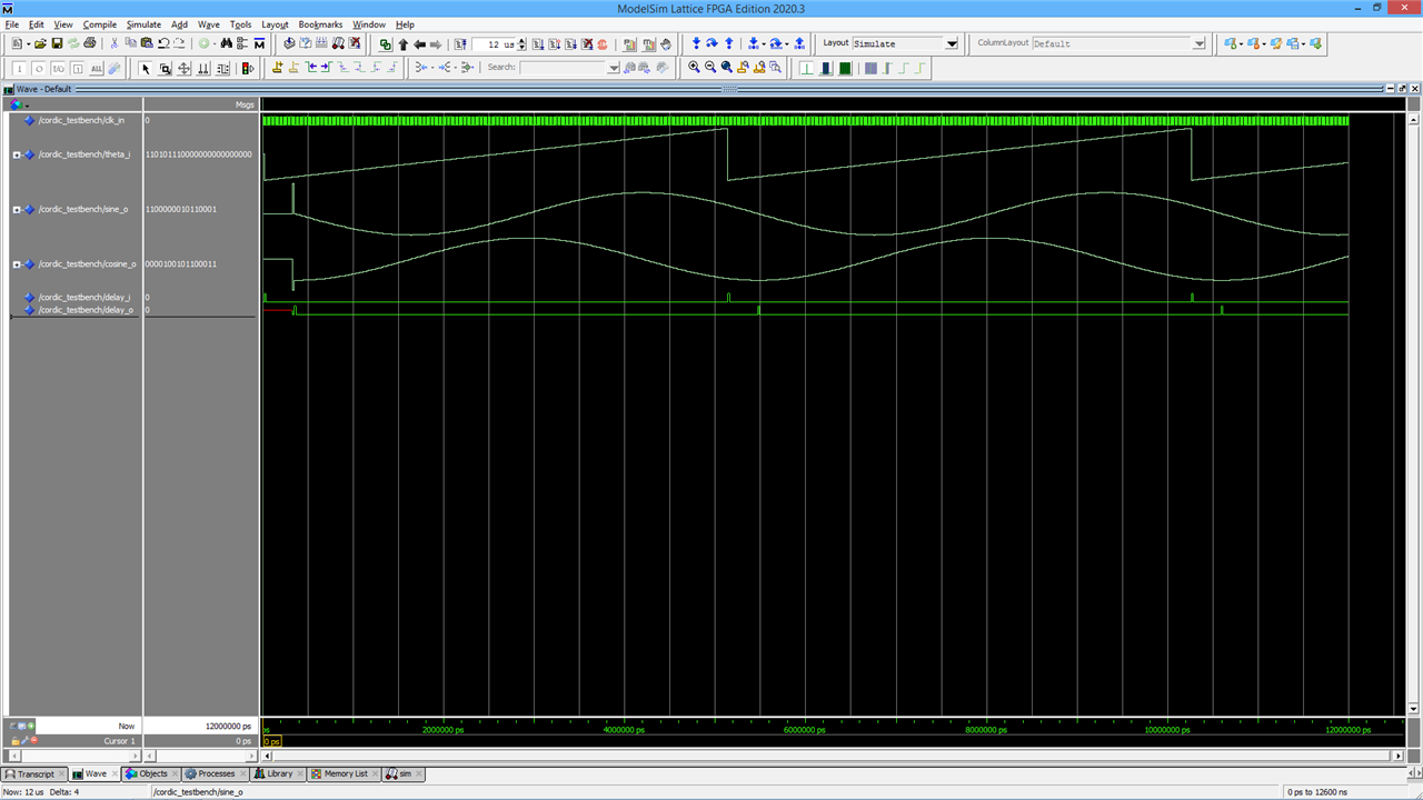
and here are the results of running the simulation where we can see the sine and cosine outputs doing their stuff.
Work in Progress
That's the point I've currently reached with it. I need to do a bit more with the simulator to verify that the sine and cosine values are correct. Then I'll try it with the various FPGAs I've got access to (all quite small - the largest is the Cyclone 10CL016 on the Vidor 4000 board, but for that I'd have to try and puzzle out again how to get the image on to it).
I've tried synthesising at various output resolutions to target the 5k XP2 on my Brevia evaluation board, to get a feel for the size and how it scales (in theory it should be roughly a square law), and this is what I'm seeing
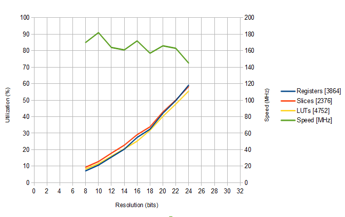
At 24 bits, it's around the 60% mark, so quite cramped if there were very much with it. At 16 bits, it's coming in at around a much more comfortable 30%, so I could probably do a project of some sort with that. The speed values are the rough ones given by the synthesis overview. Leaving aside the natural variation from different placement/routing runs, it's evident that the speed is gradually dropping with greater resolution, though more than a hundred million sine/cosine pairs a second isn't too bad a result.
The CORDIC Component Version 2
I've reworked the component so that there's now a single bit of extra headroom. I've also adjusted the starting magnitude of the cos vector by a very slight amount to take into account that the 2's complement representation doesn't allow us to represent the same number of positive and negative numbers.
The bit of headroom steals from the existing internal resolution (if it's a problem, the internal resolution can be adjusted).
-------------------------------------------------------------------------------
-- cordic.vhd                                                                --
--                                                                           --
-- VHDL component to implement a fast, pipelined CORDIC sine                 --
-- and cosine calculation.                                                   --
--                                                                           --
-- Two generics specify the desired resolutions for input and output.        --
-- A delay chain sits alongside the CORDIC pipeline to relate the output to  --
-- the input.                                                                --
--                                                                           --
-- Developed for XP2 using LSE in Diamond 3.12, but fairly                   --
-- standard VHDL and no Lattice IP components so should work                 --
-- with any FPGA.                                                            --
--                                                                           --
-- Number of CORDIC stages is one more than the output resolution.           --
-- Internal data width is (output resolution * 1.25) + 2 bits.               --
--                                                                           --
-- Those two came from a paper on the subject, not my personal experience.   --
--                                                                           --
-- More information at project page:                                         --
-- element14.com                                                             --
-------------------------------------------------------------------------------
-- (c)2023 Jon Clift 7th April 2023                                          --
-- Free to use however you want. No warranty as to correctness.              --
-- No guarantee of fitness for any purpose. No obligation to support.        --
-------------------------------------------------------------------------------
-- Rev Date         Comments                                                 --
-- 01  31-Mar-2023  internally overflows with sin or cos close to 1          --
-- 02  07-Apr-2023  added extra bit of headroom                              --
-------------------------------------------------------------------------------

library ieee;
use ieee.std_logic_1164.all;
use ieee.numeric_std.all;
use ieee.math_real.all;

entity cordic is
    generic(
        input_resol: POSITIVE;                     --- input resolution
        output_resol: POSITIVE);                   --- output resolution
    port(
        clk_in: in STD_LOGIC;                      --- clock in
        delay_in: in STD_LOGIC;                    --- delay in
        delay_out: out STD_LOGIC;                  --- delay out
        theta: in SIGNED(input_resol-1 downto 0);       --- phase in
        sine: out SIGNED(output_resol-1 downto 0);       --- sine out
        cosine: out SIGNED(output_resol-1 downto 0));    --- cosine out
end entity cordic;

architecture arch_cordic of cordic is

--- declare the addsub component

component addsub is
    generic(
        resol: POSITIVE);                --- resolution (bits)
    port(
        clk_in: in STD_LOGIC;                 --- clock in
        a: in SIGNED(resol-1 downto 0);      --- a in
        b: in SIGNED(resol-1 downto 0);      --- b in
        d: in STD_LOGIC;                      --- d=0 add, d=1 subtract
        s: out SIGNED(resol-1 downto 0));    --- sum out
end component addsub;

constant WORD_SIZE: POSITIVE := output_resol + (output_resol/4) + 2;

type MY_STD_LOGIC_ARRAY_TYPE is array(output_resol downto 0) of STD_LOGIC;
type MY_SIGNED_ARRAY_TYPE is array(output_resol downto 0) of SIGNED(WORD_SIZE-1 downto 0);

signal temp_phase: SIGNED(WORD_SIZE downto 0);
signal start_angle: SIGNED(WORD_SIZE-1 downto 0);
signal del: MY_STD_LOGIC_ARRAY_TYPE;
signal sin, cos, angle: MY_SIGNED_ARRAY_TYPE;
signal angle_coeff: MY_SIGNED_ARRAY_TYPE;
signal sin_start_value, cos_start_value, cos_start_value_p, cos_start_value_n: SIGNED(WORD_SIZE-1 downto 0);
signal initial_dir, not_initial_dir: STD_LOGIC;
signal dir, not_dir: MY_STD_LOGIC_ARRAY_TYPE;
signal shift_cos, shift_sin: MY_SIGNED_ARRAY_TYPE;

-- function to resize fractional binary numbers (note: numeric_std RESIZE doesn't work for this because the assumed binary point is down the other end)

function fractional_resize (arg: SIGNED; new_size: NATURAL) return SIGNED is
    variable result: SIGNED(new_size-1 downto 0) := (others => '0');
    begin
        if (new_size = arg'length) then
	        result := arg;
        end if;
        if (new_size < arg'length) then
            result(new_size-1 downto 0) := arg(arg'left downto arg'length - result'length);
        end if;
        if (new_size > arg'length) then
            result(new_size-1 downto new_size-result'length) := arg(arg'left downto 0);
        end if;
        return result;
    end fractional_resize;

-- now for the component code

begin

 	temp_phase <= fractional_resize(theta,temp_phase'length);
    start_angle(start_angle'length-1 downto 0) <= temp_phase(temp_phase'length-2 downto 0);

    --- process to calculate the inverse-tangent coefficients and the overall gain (which will determine the cos start values)
	--- synthesis will understand to just calculate the values and then hardwire them into the final logic
	--- none of this floating-point calculation stuff will end up as logic in the FPGA

    calc_process: process
	    variable temp: REAL;
	    begin
        coeff_calc: for i in 0 to output_resol loop
            angle_coeff(i) <= to_signed(integer(round((2.0**real(WORD_SIZE-1)) * (arctan(2.0**(-1.0 * real(i))) / math_pi_over_2))),WORD_SIZE);
        end loop coeff_calc;
		temp := 1.0;
        gain_calc: for i in 0 to output_resol loop
            temp := temp * sqrt(1.0 + (2.0**(-2.0 * real(i))));
        end loop gain_calc;
		temp := (0.5 - (2.0**(-1.0 * real(output_resol-1))/2.0)) / temp;   --- adjustment to stop overflow (not very scientific!)
        cos_start_value_p <= to_signed(integer(trunc((2.0**real(WORD_SIZE-1)) * temp)),WORD_SIZE);
        cos_start_value_n <= to_signed(integer(trunc(-1.0 * (2.0**real(WORD_SIZE-1)) * temp)),WORD_SIZE);
		sin_start_value <= (others => '0');
		wait;
    end process calc_process;

	--- now generate the logic for the cordic stages

    cordic_stages: for k in 0 to output_resol generate

    begin
        first_stage: if(k = 0) generate
        begin
            first_stage_process: process (clk_in,theta)
            begin
                if (clk_in'event and clk_in='1') then
                    del(0) <= delay_in;
				end if;
			end process;
			cos_start_value <= cos_start_value_p when ((theta(theta'length-1) xor theta(theta'length-2)) = '0') else cos_start_value_n;
			initial_dir <= theta(theta'length-2);
			not_initial_dir <= not theta(theta'length-2);
            addsub_1: component addsub generic map(resol => WORD_SIZE) port map(clk_in => clk_in, a => sin_start_value, b => cos_start_value, d => initial_dir, s => sin(0));
            addsub_2: component addsub generic map(resol => WORD_SIZE) port map(clk_in => clk_in, a => cos_start_value, b => sin_start_value, d => not_initial_dir, s => cos(0));
            addsub_3: component addsub generic map(resol => WORD_SIZE) port map(clk_in => clk_in, a => start_angle, b => angle_coeff(0), d => not_initial_dir, s => angle(0));
		end generate first_stage;

		other_stages: if(k /= 0) generate
		begin
            other_stages_process: process (clk_in)
            begin
                if (clk_in'event and clk_in='1') then
                    del(k) <= del(k-1);
				end if;
			end process;
    		shift_cos(k) <= shift_right(cos(k-1),k);
	    	shift_sin(k) <= shift_right(sin(k-1),k);
			dir(k) <= angle(k-1)(WORD_SIZE-1);
			not_dir(k) <= not angle(k-1)(WORD_SIZE-1);
            addsub_4: component addsub generic map(resol => WORD_SIZE) port map(clk_in => clk_in, a => sin(k-1), b => shift_cos(k), d => dir(k), s => sin(k));
            addsub_5: component addsub generic map(resol => WORD_SIZE) port map(clk_in => clk_in, a => cos(k-1), b => shift_sin(k), d => not_dir(k), s => cos(k));
            addsub_6: component addsub generic map(resol => WORD_SIZE) port map(clk_in => clk_in, a => angle(k-1), b => angle_coeff(k), d => not_dir(k), s => angle(k));
		end generate other_stages;

    end generate cordic_stages;

    --- connect outputs to signals in design
	--- sine and cosine results need resizing (this is crude truncation)
	--- also need to exclude the additional overhead bit

    delay_out <= del(output_resol);
    sine(output_resol-1) <= sin(output_resol)(WORD_SIZE-1);
    sine(output_resol-2 downto 0) <= sin(output_resol)(WORD_SIZE-3 downto (WORD_SIZE-output_resol)-1);
    cosine(output_resol-1) <= cos(output_resol)(WORD_SIZE-1);
    cosine(output_resol-2 downto 0) <= cos(output_resol)(WORD_SIZE-3 downto (WORD_SIZE-output_resol)-1);

end arch_cordic;

-------------------------------------------------------------------------------
-- addsub                                                                    --
--                                                                           --
-- VHDL component to implement 2's complement add or subtract                --
-- no output carry                                                           --
-- registered output for the pipeline                                        --
-------------------------------------------------------------------------------
library ieee;
use ieee.std_logic_1164.all;
use ieee.numeric_std.all;

entity addsub is
    generic(
        resol: POSITIVE);             --- desired resolution (bits)
    port(
        clk_in: in STD_LOGIC;                 --- clock in
        a: in SIGNED(resol-1 downto 0);      --- a in
        b: in SIGNED(resol-1 downto 0);      --- b in
        d: in STD_LOGIC;                      --- d=0 add, d=1 subtract
        s: out SIGNED(resol-1 downto 0));    --- sum out
end entity addsub;

-- this version uses numeric_std addition and subtraction.
-- synthesis seems to build both and place a mux on output to select which result we want.
-- not necessarily good for space
-- but synthesis knows how to use fast carry-chain logic to good advantage

architecture arch_addsub of addsub is

signal result: SIGNED(resol-1 downto 0):= (others => '0');

begin

    add_sub_process: process (clk_in)
    begin
        if (rising_edge(clk_in)) then
	        if(d = '0') then
                result <= a + b;
            else
                result <= a - b;
            end if;
	    end if;
    end process;

    s <= result;

end arch_addsub;
Simulator Testing
To test it, I've created a modified version of the CORDIC component that feeds out an extra four lsb bits from the internal wordlength.
here's the modified component
-------------------------------------------------------------------------------
-- cordic-sim.vhd         cordic.vhd adapted for simulation test             --
--                                                                           --
-- VHDL component to implement a fast, pipelined CORDIC sine                 --
-- and cosine calculation.                                                   --
--                                                                           --
-- Two generics specify the desired resolutions for input and output.        --
-- A delay chain sits alongside the CORDIC pipeline to relate the output to  --
-- the input.                                                                --
--                                                                           --
-- Developed for XP2 using LSE in Diamond 3.12, but fairly                   --
-- standard VHDL and no Lattice IP components so should work                 --
-- with any FPGA.                                                            --
--                                                                           --
-- Number of CORDIC stages is one more than the output resolution.           --
-- Internal data width is (output resolution * 1.25) + 2 bits.               --
--                                                                           --
-- Those two came from a paper on the subject, not my personal experience.   --
--                                                                           --
-- More information at project page:                                         --
-- element14.com                                                             --
-------------------------------------------------------------------------------
-- (c)2023 Jon Clift 7th April 2023                                          --
-- Free to use however you want. No warranty as to correctness.              --
-- No guarantee of fitness for any purpose. No obligation to support.        --
-------------------------------------------------------------------------------
-- Rev Date         Comments                                                 --
-- 01  31-Mar-2023  internally overflows with sin or cos close to 1          --
-- 02  07-Apr-2023  added extra bit of headroom                              --
-------------------------------------------------------------------------------

library ieee;
use ieee.std_logic_1164.all;
use ieee.numeric_std.all;
use ieee.math_real.all;

entity cordic is
    generic(
        input_resol: POSITIVE:= 32;               --- input resolution
        output_resol: POSITIVE:= 16);               --- output resolution
    port(
        clk_in: in STD_LOGIC;                      --- clock in
        delay_in: in STD_LOGIC;                    --- delay in
        delay_out: out STD_LOGIC;                  --- delay out
        theta: in SIGNED(input_resol-1 downto 0);       --- phase in
--        sine: out SIGNED(output_resol-1 downto 0);       --- sine out
--        cosine: out SIGNED(output_resol-1 downto 0));    --- cosine out
        sine: out SIGNED(output_resol+3 downto 0);       --- sine out
        cosine: out SIGNED(output_resol+3 downto 0));    --- cosine out
end entity cordic;

architecture arch_cordic of cordic is

--- declare the addsub component

component addsub is
    generic(
        resol: POSITIVE);                --- resolution (bits)
    port(
        clk_in: in STD_LOGIC;                 --- clock in
        a: in SIGNED(resol-1 downto 0);      --- a in
        b: in SIGNED(resol-1 downto 0);      --- b in
        d: in STD_LOGIC;                      --- d=0 add, d=1 subtract
        s: out SIGNED(resol-1 downto 0));    --- sum out
end component addsub;

constant WORD_SIZE: POSITIVE := output_resol + (output_resol/4) + 2;

type MY_STD_LOGIC_ARRAY_TYPE is array(output_resol downto 0) of STD_LOGIC;
type MY_SIGNED_ARRAY_TYPE is array(output_resol downto 0) of SIGNED(WORD_SIZE-1 downto 0);

signal temp_phase: SIGNED(WORD_SIZE downto 0);
signal start_angle: SIGNED(WORD_SIZE-1 downto 0);
signal del: MY_STD_LOGIC_ARRAY_TYPE;
signal sin, cos, angle: MY_SIGNED_ARRAY_TYPE;
signal angle_coeff: MY_SIGNED_ARRAY_TYPE;
signal sin_start_value, cos_start_value, cos_start_value_p, cos_start_value_n: SIGNED(WORD_SIZE-1 downto 0);
signal initial_dir, not_initial_dir: STD_LOGIC;
signal dir, not_dir: MY_STD_LOGIC_ARRAY_TYPE;
signal shift_cos, shift_sin: MY_SIGNED_ARRAY_TYPE;

-- function to resize fractional binary numbers (note: numeric_std RESIZE doesn't work for this because the assumed binary point is down the other end)

function fractional_resize (arg: SIGNED; new_size: NATURAL) return SIGNED is
    variable result: SIGNED(new_size-1 downto 0) := (others => '0');
    begin
        if (new_size = arg'length) then
	        result := arg;
        end if;
        if (new_size < arg'length) then
            result(new_size-1 downto 0) := arg(arg'left downto arg'length - result'length);
        end if;
        if (new_size > arg'length) then
            result(new_size-1 downto new_size-result'length) := arg(arg'left downto 0);
        end if;
        return result;
    end fractional_resize;

-- now for the component code

begin

 	temp_phase <= fractional_resize(theta,temp_phase'length);
    start_angle(start_angle'length-1 downto 0) <= temp_phase(temp_phase'length-2 downto 0);

    --- process to calculate the inverse-tangent coefficients and the overall gain (which will determine the cos start values)
	--- synthesis will understand to just calculate the values and then hardwire them into the final logic
	--- none of this floating-point calculation stuff will end up as logic in the FPGA

    calc_process: process
	    variable temp: REAL;
	    begin
        coeff_calc: for i in 0 to output_resol loop
            angle_coeff(i) <= to_signed(integer(round((2.0**real(WORD_SIZE-1)) * (arctan(2.0**(-1.0 * real(i))) / math_pi_over_2))),WORD_SIZE);
        end loop coeff_calc;
		temp := 1.0;
        gain_calc: for i in 0 to output_resol loop
            temp := temp * sqrt(1.0 + (2.0**(-2.0 * real(i))));
        end loop gain_calc;
--		temp := 0.5 / temp;   --- effectively gives one bit of overhead to sine and cosine calculation
		temp := (0.5 - (2.0**(-1.0 * real(output_resol-1))/2.0)) / temp;   --- now with adjustment to stop overflow (not very scientific!)
        cos_start_value_p <= to_signed(integer(trunc((2.0**real(WORD_SIZE-1)) * temp)),WORD_SIZE);
        cos_start_value_n <= to_signed(integer(trunc(-1.0 * (2.0**real(WORD_SIZE-1)) * temp)),WORD_SIZE);
		sin_start_value <= (others => '0');
		wait;
    end process calc_process;

	--- now generate the logic for the cordic stages

    cordic_stages: for k in 0 to output_resol generate

    begin
        first_stage: if(k = 0) generate
        begin
            first_stage_process: process (clk_in,theta)
            begin
                if (clk_in'event and clk_in='1') then
                    del(0) <= delay_in;
				end if;
			end process;
			cos_start_value <= cos_start_value_p when ((theta(theta'length-1) xor theta(theta'length-2)) = '0') else cos_start_value_n;
			initial_dir <= theta(theta'length-2);
			not_initial_dir <= not theta(theta'length-2);
            addsub_1: component addsub generic map(resol => WORD_SIZE) port map(clk_in => clk_in, a => sin_start_value, b => cos_start_value, d => initial_dir, s => sin(0));
            addsub_2: component addsub generic map(resol => WORD_SIZE) port map(clk_in => clk_in, a => cos_start_value, b => sin_start_value, d => not_initial_dir, s => cos(0));
            addsub_3: component addsub generic map(resol => WORD_SIZE) port map(clk_in => clk_in, a => start_angle, b => angle_coeff(0), d => not_initial_dir, s => angle(0));
		end generate first_stage;

		other_stages: if(k /= 0) generate
		begin
            other_stages_process: process (clk_in)
            begin
                if (clk_in'event and clk_in='1') then
                    del(k) <= del(k-1);
				end if;
			end process;
    		shift_cos(k) <= shift_right(cos(k-1),k);
	    	shift_sin(k) <= shift_right(sin(k-1),k);
			dir(k) <= angle(k-1)(WORD_SIZE-1);
			not_dir(k) <= not angle(k-1)(WORD_SIZE-1);
            addsub_4: component addsub generic map(resol => WORD_SIZE) port map(clk_in => clk_in, a => sin(k-1), b => shift_cos(k), d => dir(k), s => sin(k));
            addsub_5: component addsub generic map(resol => WORD_SIZE) port map(clk_in => clk_in, a => cos(k-1), b => shift_sin(k), d => not_dir(k), s => cos(k));
            addsub_6: component addsub generic map(resol => WORD_SIZE) port map(clk_in => clk_in, a => angle(k-1), b => angle_coeff(k), d => not_dir(k), s => angle(k));
		end generate other_stages;

    end generate cordic_stages;

    --- connect outputs to signals in design
	--- sine and cosine results need resizing (this is crude truncation)
	--- also need to exclude the additional overhead bit

    delay_out <= del(output_resol);
--    sine(output_resol-1) <= sin(output_resol)(WORD_SIZE-1);
--    sine(output_resol-2 downto 0) <= sin(output_resol)(WORD_SIZE-3 downto (WORD_SIZE-output_resol)-1);
--    cosine(output_resol-1) <= cos(output_resol)(WORD_SIZE-1);
--    cosine(output_resol-2 downto 0) <= cos(output_resol)(WORD_SIZE-3 downto (WORD_SIZE-output_resol)-1);
    sine(output_resol+3) <= sin(output_resol)(WORD_SIZE-1);
    sine(output_resol+2 downto 0) <= sin(output_resol)(WORD_SIZE-3 downto 1);
    cosine(output_resol+3) <= cos(output_resol)(WORD_SIZE-1);
    cosine(output_resol+2 downto 0) <= cos(output_resol)(WORD_SIZE-3 downto 1);

end arch_cordic;

-------------------------------------------------------------------------------
-- addsub                                                                    --
--                                                                           --
-- VHDL component to implement 2's complement add or subtract                --
-- no output carry                                                           --
-- registered output for the pipeline                                        --
-------------------------------------------------------------------------------
library ieee;
use ieee.std_logic_1164.all;
use ieee.numeric_std.all;

entity addsub is
    generic(
        resol: POSITIVE);             --- desired resolution (bits)
    port(
        clk_in: in STD_LOGIC;                 --- clock in
        a: in SIGNED(resol-1 downto 0);      --- a in
        b: in SIGNED(resol-1 downto 0);      --- b in
        d: in STD_LOGIC;                      --- d=0 add, d=1 subtract
        s: out SIGNED(resol-1 downto 0));    --- sum out
end entity addsub;

-- this version uses numeric_std addition and subtraction.
-- synthesis seems to build both and place a mux on output to select which result we want.
-- not necessarily good for space
-- but synthesis knows how to use fast carry-chain logic to good advantage

architecture arch_addsub of addsub is

signal result: SIGNED(resol-1 downto 0):= (others => '0');

begin

    add_sub_process: process (clk_in)
    begin
        if (rising_edge(clk_in)) then
	        if(d = '0') then
                result <= a + b;
            else
                result <= a - b;
            end if;
	    end if;
    end process;

    s <= result;

end arch_addsub;
and here's a more developed testbench that calculates what the sine and cosine should be, and calculates an epsilon value that is the difference between what my component calculates and what the simulator does.
------------------------------------------------------------------
--          ***** XP2_cordic_testbench-sim.vhd *****            --
-- use with cordic-sim.vhd component                            --
-- Simple testbench for CORDIC sine and cosine component        --
-- This is procedural. The stimulus values for theta are        --
-- calculated and sent to the component on successive clock     --
-- edges.                                                       --
-- The values output, after the pipeline delay, are compared    --
-- with those expected.                                         --
------------------------------------------------------------------
-- JC 31st March 2023                                           --
------------------------------------------------------------------
-- Rev    Date         Comments                                 --
-- 01     31-Mar-2023                                           --
-- 02     07-Apr-2023                                           --
------------------------------------------------------------------

library ieee;
use ieee.std_logic_1164.all;
use ieee.numeric_std.all;
use ieee.math_real.all;

entity cordic_testbench_sim is end cordic_testbench_sim;

architecture arch_cordic_testbench of cordic_testbench_sim is

constant T_clk: TIME := 10ns;			--- clock low or clock high time, clock period is 2 * T_clk
constant in_res: POSITIVE := 24;		--- input resolution (bits)
constant out_res: POSITIVE := 16;		--- output resolution (bits)
constant steps: POSITIVE := 256;        --- number of test vectors

signal clk_in: STD_LOGIC := '0';
signal theta_i: SIGNED(in_res-1 downto 0);
--signal sine_o: SIGNED(out_res-1 downto 0);
--signal cosine_o: SIGNED(out_res-1 downto 0);
signal sine_o: SIGNED(out_res+3 downto 0);
signal cosine_o: SIGNED(out_res+3 downto 0);
signal delay_i: STD_LOGIC := '0';
signal delay_o: STD_LOGIC;
signal calc_sine: SIGNED(out_res-1 downto 0);
signal calc_cosine: SIGNED(out_res-1 downto 0);
--type my_pipeline_type is array (out_res downto 0) of real;
--variable angle: REAL:= -1.0;	--- start with phase of -180 degrees
--variable angle_increment: REAL;
signal sine_epsilon: SIGNED(out_res+3 downto 0);
signal cosine_epsilon: SIGNED(out_res+3 downto 0);
signal sine_pipe_out: SIGNED(out_res+3 downto 0);
signal cosine_pipe_out: SIGNED(out_res+3 downto 0);
--variable angle_pipeline: my_pipeline_type;

--- declare the cordic component

component cordic is
    generic(
        input_resol: POSITIVE;               --- desired input resolution (bits)
        output_resol: POSITIVE);             --- desired output resolution (bits)
    port(
        clk_in: in STD_LOGIC;                      --- clock in
        delay_in: in STD_LOGIC;                    --- delay in
        delay_out: out STD_LOGIC;                  --- delay out
        theta: in SIGNED(in_res-1 downto 0);       --- phase in
--        sine: out SIGNED(out_res-1 downto 0);       --- sine out
--        cosine: out SIGNED(out_res-1 downto 0));    --- cosine out
        sine: out SIGNED(out_res+3 downto 0);       --- sine out
        cosine: out SIGNED(out_res+3 downto 0));    --- cosine out
end component;

begin
    --- instance of cordic component

    cordic_1: component cordic
        generic map(
            input_resol => in_res,          --- input resolution
            output_resol => out_res)          --- output resolution
        port map(
            clk_in => clk_in,      --- clock in
            delay_in => delay_i,   --- delay in
            delay_out => delay_o,  --- delay out
            theta => theta_i,      --- phase in
            sine => sine_o,        --- sine out
            cosine => cosine_o);   --- cosine out

    --- generate a continuous clock to drive everything

    clock_proc: process
        begin
	        clk_in <= '1' after T_clk, '0' after 2 * T_clk;
		    wait for 2 * T_clk;
	    end process clock_proc;

    --- calculate theta (phase) values to send to the CORDIC component
	--- the values are also sent along a pipeline that matches the delay through the CORDIC component
	--- at the end, the component's sine and cos values are compared with ones calculated by the simulator
	--- epsilon is the difference (in bits - lower 4 bits are fractional)

    stimulus_proc: process
	    type my_pipeline_type is array (out_res downto 0) of real;
        variable angle: REAL:= -1.0;	--- start with phase of -180 degrees
        variable angle_increment: REAL;
--	    variable sine_epsilon: SIGNED(out_res+3 downto 0);
--	    variable cosine_epsilon: SIGNED(out_res+3 downto 0);
--	    variable sine_pipe_out: SIGNED(out_res+3 downto 0);
--	    variable cosine_pipe_out: SIGNED(out_res+3 downto 0);
		variable angle_pipeline: my_pipeline_type;
        begin
            angle := 1.0;
            angle_increment := 2.0 / real(steps);
            test_loop: for i in 0 to steps-1 loop
	            wait until clk_in'event and clk_in = '0';
				--- calculate the CORDIC input
                theta_i <= to_signed(integer(round((2.0**real(in_res-1)) * angle)),in_res);
				--- pipeline
				pipe_loop: for j in out_res downto 1 loop
				    angle_pipeline(j) := angle_pipeline(j-1);
				end loop pipe_loop;
				angle_pipeline(0) := angle;
				--- calculate the sine and cos from the angle
--                sine_pipe_out <= to_signed(integer(round((2.0**real(out_res-1)) * sin(angle_pipeline(out_res) * MATH_PI))),out_res);
--                cosine_pipe_out <= to_signed(integer(round((2.0**real(out_res-1)) * cos(angle_pipeline(out_res) * MATH_PI))),out_res);
				--- do the comparison
	            wait until clk_in'event and clk_in = '1';
                sine_pipe_out <= to_signed(integer(round((2.0**real(out_res+3)) * sin(angle_pipeline(out_res) * MATH_PI))),out_res+4);
                cosine_pipe_out <= to_signed(integer(round((2.0**real(out_res+3)) * cos(angle_pipeline(out_res) * MATH_PI))),out_res+4);
				sine_epsilon <= sine_pipe_out - sine_o;
				cosine_epsilon <= cosine_pipe_out - cosine_o ;
				--- update the angle
                angle := angle + angle_increment;
				--- drive delay_i high at start of cycle so we can see it doing something
				if(i = 0) then
	    	        delay_i <= '1';
				else
    		        delay_i <= '0';
				end if;
            end loop test_loop;
        end process stimulus_proc;

end arch_cordic_testbench;
Here's what the simulator sees for the sine. theta_i is the phase, swept from -180 to + 180 n 256 steps, sine_o is the output of the CORDIC component (it lags the phase because of the intenal pieline), sine_pipe_out is the sine calculated by the simulator, and sine_epsilon is the difference.
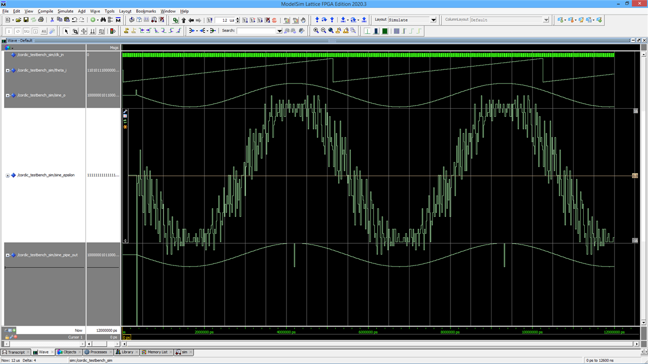
the +16 and -16 horizontal lines on the epsilon waveform are, in effect, equivalent to plus or minus one bit of sine_o from the standard, non-test component.
The overall sine shape of the error epsilon comes from my adjusting the component's sine so that it is one lsb short of the maximum (for a 16-bit component, the sine runs from a min of -32767 to a max of 32767), in order that there be no wrap-around. I haven't done that for the simulator's sine, so it does wrap around and will be one out at the extremes. What I'm more interested in is how it varies as it goes along between the extreme values. There appears to be up to about 3/4 of a bit of variation. For some purposes, that would be fine, but for more demanding applications we might want to have it a bit better than that so that when properly rounded it would hit the correct values. It looks like adding back the bit stolen for the overhead would probably be enough.
Although this is not a exhaustive test, I'm only running through 256 different phases here, because of the way that the algorithm does a kind of successive approximation I don't think that there will be any rogue values that are a long way out. The small errors here are simply down to accumulation from the finite arithmetic precision.
Next thing is an I2S interface to couple it to a CODEC and see what comes out.
Follow-up blog here: Fast VHDL CORDIC Sine and Cosine Component on Lattice XP2 Device Using Diamond 3.12 Part 2
[1] /technologies/fpga-group/b/blog/posts/fpga-making-waves
[2] http://www.latticesemi.com/en/Products/DevelopmentBoardsAndKits/LatticeXP2Brevia2DevelopmentKit.aspx

