element14 Community
element14 Community
    Register Log In
  • Site
  • Search
  • Log In Register
  • Community Hub
    Community Hub
    • What's New on element14
    • Feedback and Support
    • Benefits of Membership
    • Personal Blogs
    • Members Area
    • Achievement Levels
  • Learn
    Learn
    • Ask an Expert
    • eBooks
    • element14 presents
    • Learning Center
    • Tech Spotlight
    • STEM Academy
    • Webinars, Training and Events
    • Learning Groups
  • Technologies
    Technologies
    • 3D Printing
    • FPGA
    • Industrial Automation
    • Internet of Things
    • Power & Energy
    • Sensors
    • Technology Groups
  • Challenges & Projects
    Challenges & Projects
    • Design Challenges
    • element14 presents Projects
    • Project14
    • Arduino Projects
    • Raspberry Pi Projects
    • Project Groups
  • Products
    Products
    • Arduino
    • Avnet Boards Community
    • Dev Tools
    • Manufacturers
    • Multicomp Pro
    • Product Groups
    • Raspberry Pi
    • RoadTests & Reviews
  • About Us
  • Store
    Store
    • Visit Your Store
    • Choose another store...
      • Europe
      •  Austria (German)
      •  Belgium (Dutch, French)
      •  Bulgaria (Bulgarian)
      •  Czech Republic (Czech)
      •  Denmark (Danish)
      •  Estonia (Estonian)
      •  Finland (Finnish)
      •  France (French)
      •  Germany (German)
      •  Hungary (Hungarian)
      •  Ireland
      •  Israel
      •  Italy (Italian)
      •  Latvia (Latvian)
      •  
      •  Lithuania (Lithuanian)
      •  Netherlands (Dutch)
      •  Norway (Norwegian)
      •  Poland (Polish)
      •  Portugal (Portuguese)
      •  Romania (Romanian)
      •  Russia (Russian)
      •  Slovakia (Slovak)
      •  Slovenia (Slovenian)
      •  Spain (Spanish)
      •  Sweden (Swedish)
      •  Switzerland(German, French)
      •  Turkey (Turkish)
      •  United Kingdom
      • Asia Pacific
      •  Australia
      •  China
      •  Hong Kong
      •  India
      •  Korea (Korean)
      •  Malaysia
      •  New Zealand
      •  Philippines
      •  Singapore
      •  Taiwan
      •  Thailand (Thai)
      • Americas
      •  Brazil (Portuguese)
      •  Canada
      •  Mexico (Spanish)
      •  United States
      Can't find the country/region you're looking for? Visit our export site or find a local distributor.
  • Translate
  • Profile
  • Settings
FPGA
  • Technologies
  • More
FPGA
Blog Learning AMD Zynq: a project to generate a set of PWM signals. 2 - add overall control block, delay and pulse signal
  • Blog
  • Forum
  • Documents
  • Quiz
  • Events
  • Polls
  • Files
  • Members
  • Mentions
  • Sub-Groups
  • Tags
  • More
  • Cancel
  • New
Join FPGA to participate - click to join for free!
  • Share
  • More
  • Cancel
Group Actions
  • Group RSS
  • More
  • Cancel
Engagement
  • Author Author: Jan Cumps
  • Date Created: 4 May 2023 8:15 PM Date Created
  • Views 4951 views
  • Likes 8 likes
  • Comments 49 comments
  • pynq-z2
  • amdzynqultrasoundpulse
  • zynq
  • fpga
  • vivado
  • vhdl
  • pynq
  • spartan
Related
Recommended

Learning AMD Zynq: a project to generate a set of PWM signals. 2 - add overall control block, delay and pulse signal

Jan Cumps
Jan Cumps
4 May 2023
Learning AMD Zynq: a project to generate a set of PWM signals. 2 - add overall control block, delay and pulse signal

Continuation of  Learning AMD Zynq: a project to generate a set of PWM signals. 1 - problem statement and possible approach .

 yepe has a goal to create a set of signals for an ultrasone pulse generator.

image

Status after Post 1

In Post 1, we got the PWM and PWMN signals, and a first stab at the PULSE signal. Let's start at that stable point here, and try to add

  • the initial delay between PRF falling edge and the start of the pulse train
  • a PULSE signal that starts and ends exactly when the pulse train starts and ends.

Here's the design from the 1st blog:

image

The clocking wizard generates a 320 MHz clock. High enough to give the PWM signal a decent granularity for the dead times (2.5 ns steps).
The PWM generator generates 2 complementary signals, PWM and PWMN, with configurable deadband.
The PWM generator has an enable pin. When that pin is low, it will set PWM low and PWMN high, else it outputs the train of pulses
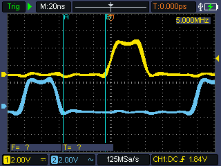
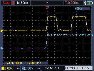
image image

Goal of this post:

  • Build a control block that will tell the PWM when to generate pulses (control its enable)
  • let that block also control the PULSE signal
  • establish the configurable? delay at the start
  • maybe handle PRF?

What this session will not do: handle GATE

Same as in post 1, the action will be in the comments. It's a collaborative exercise.

Update 4/5/2023:

Possible signal controller design (partly - not all states and signals implemented)
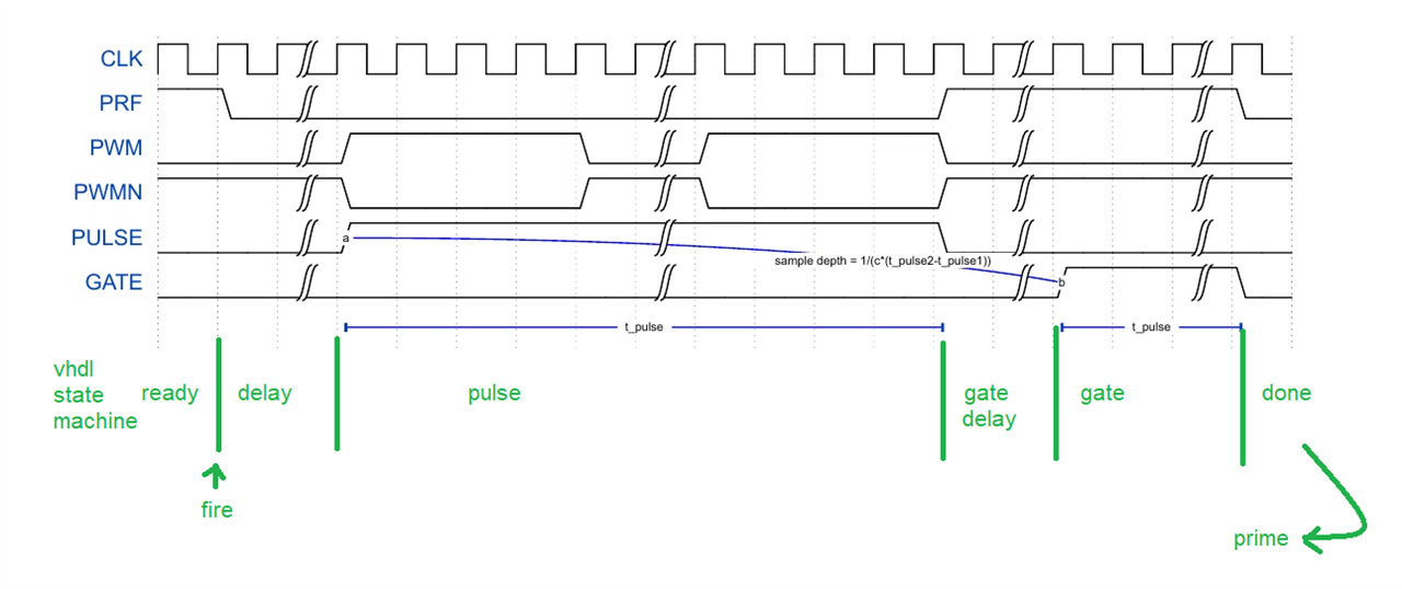
image

library IEEE;
use IEEE.STD_LOGIC_1164.ALL;

package PulsePckg is

    component signal_controller is
        generic (
            start_delay_resolution : integer := 6;  -- bit width of the counter used delaying pulse train start
            train_length           : integer := 7;  -- bit width of the PWM burst train counter
            gate_delay_resolution  : integer := 6;  -- bit width of the counter used delaying the gate signal start 
            counter_resolution     : integer := 7   -- big enought o hold the largest of above
        );
        port (
            n_reset_i     : in   std_logic;                                                -- async reset
            clk_i         : in   std_logic;                                                -- Input clock.
            start_delay_i : in   std_logic_vector (start_delay_resolution - 1 downto 0);   -- Duty-cycle input.
            train_length_i: in   std_logic_vector (train_length - 1 downto 0);             -- how many PWMs in a burst train.
            prime_i       : in   std_logic;                                                -- allow cycle start
            fire_i        : in   std_logic;                                                -- start a cycle
            prf_o         : out  std_logic;                                                -- PRF
            enable_o      : out  std_logic;                                                -- enable pwm
            pulse_o       : out  std_logic;                                                -- PULSE
            gate_o        : out  std_logic;                                                -- GATE
            leds_o        : out std_logic_vector (3 downto 0)
        );
    end component;

end package;
library IEEE;
use IEEE.STD_LOGIC_1164.ALL;
use ieee.numeric_std.all;


entity signal_controller is
    generic (
        train_length           : integer := 7;  -- bit width of the PWM burst train counter
        start_delay_resolution : integer := 6;  -- bit width of the counter used delaying pulse train start
        gate_delay_resolution  : integer := 6;  -- bit width of the counter used delaying the gate signal start 
        counter_resolution     : integer := 7   -- big enought o hold the largest of above
    );
    port (
        n_reset_i     : in   std_logic;                                                -- async reset
        clk_i         : in   std_logic;                                                -- Input clock.
        start_delay_i : in   std_logic_vector (start_delay_resolution - 1 downto 0);   -- Duty-cycle input.
        train_length_i: in   std_logic_vector (train_length - 1 downto 0);             -- how many PWMs in a burst train.
        prime_i       : in   std_logic;                                                -- allow cycle start
        fire_i        : in   std_logic;                                                -- start a cycle
        prf_o         : out  std_logic;                                                -- PRF
        enable_o      : out  std_logic;                                                -- enable pwm
        pulse_o       : out  std_logic;                                                -- PULSE
        gate_o        : out  std_logic;                                                -- GATE
        leds_o        : out std_logic_vector (3 downto 0)
    );
end signal_controller;

architecture arch of signal_controller is
    type states is (ready, delay, pulse, gate_delay, gate, done );
    signal counter : integer range 0 to 2**counter_resolution-1;
    signal state  : states;

begin


    clocked: process(clk_i)

    begin

        if rising_edge(clk_i) then
            -- sync reset
            if n_reset_i = '0' then
                counter <= 0;
                state <= ready;
                -- reset output states
                prf_o <= '1';
                enable_o <= '0';
                pulse_o <= '0';
                gate_o <= '0';
                leds_o <= (others => '0');
            else
                counter <= counter + 1;
                -- default output states
                prf_o <= '1';
                enable_o <= '0';
                pulse_o <= '0';
                gate_o <= '0';
                leds_o <= (others => '0');

                case State is

                    when ready =>  -- start a pulse group as soon as the fire bit is set
                        leds_o <= (0 => '1', others => '0');
                        -- check if the caller has reset the prime bit
                        if prime_i = '0' then
                            -- if yes, start if the fire bit is set.
                            if fire_i = '1' then
                                counter <= 0;
                                state <= delay;
                            end if;
                        end if;

                    when delay =>
                        leds_o <= (0 => '0', 1 => '1', others => '0');
                        prf_o <= '0';
                        if counter >= to_integer(unsigned(start_delay_i)) - 1 then
                            counter <= 0;
                            enable_o <= '1';
                            state <= pulse;
                        end if;

                    when pulse =>
                        leds_o <= (0 => '1', 1 => '1', others => '0');
                        enable_o <= '1';
                        prf_o <= '0';
                        if counter < to_integer(unsigned(train_length_i)) - 1 then  -- let the pulse change sync with last edge of PWM
                            pulse_o <= '1';
                        elsif counter = to_integer(unsigned(train_length_i)) - 1 then
                            pulse_o <= '1';
                            counter <= 0;
                            state <= gate_delay;
                        end if;

                    when gate_delay =>
                        leds_o <= (0 => '0', 1 => '0', 2 => '1', others => '0');
                        state <= gate;  -- todo implement

                    when gate =>
                        leds_o <= (0 => '1', 1 => '0', 2 => '1', others => '0');
                        state <= done;  -- todo implement

                    when done =>
                        leds_o <= (0 => '1', 1 => '1', 2 => '1', others => '0');
                        -- check if the caller has reset the fire bit
                        if fire_i = '0' then
                            -- if yes, prime if the prime_bit is set.
                            if prime_i = '1' then
                                counter <= 0;
                                state <= ready;
                            end if;
                        end if;

                end case;

            end if; -- sync reset
        end if; -- rising_edge

    end process clocked;

end architecture;

warning: the train length should always result in full PWM cycles. If you disable the PWM module before it had the chance to generate a full cycle, both PWM and PWMN will switch at the same time and not respect the deadband.

Block diagram:
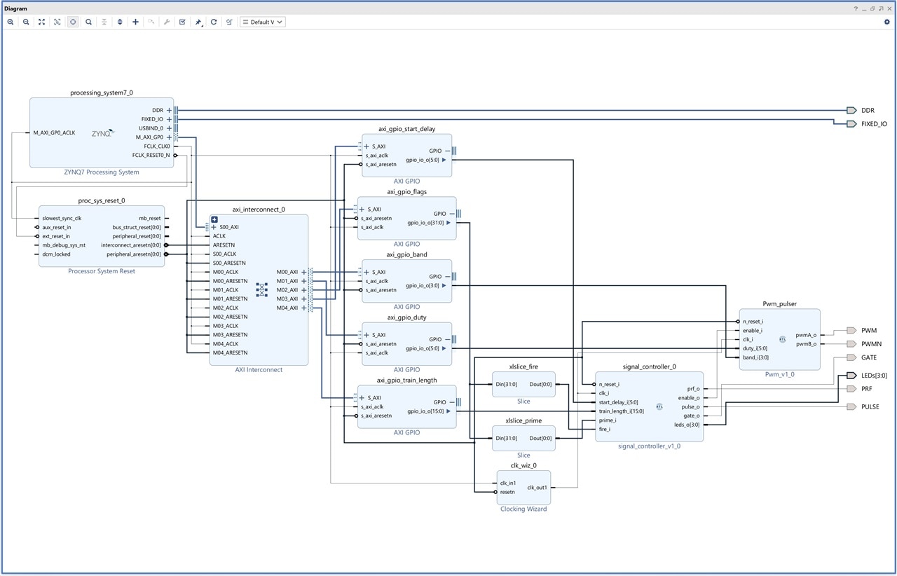
image

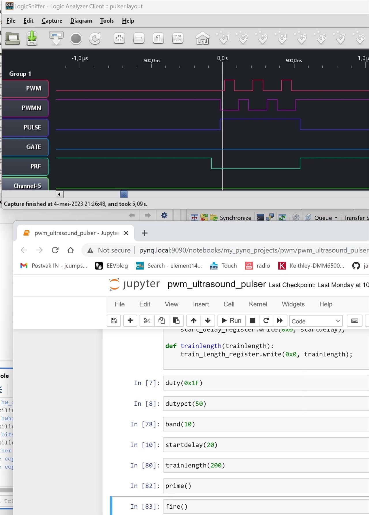
Capture:

image

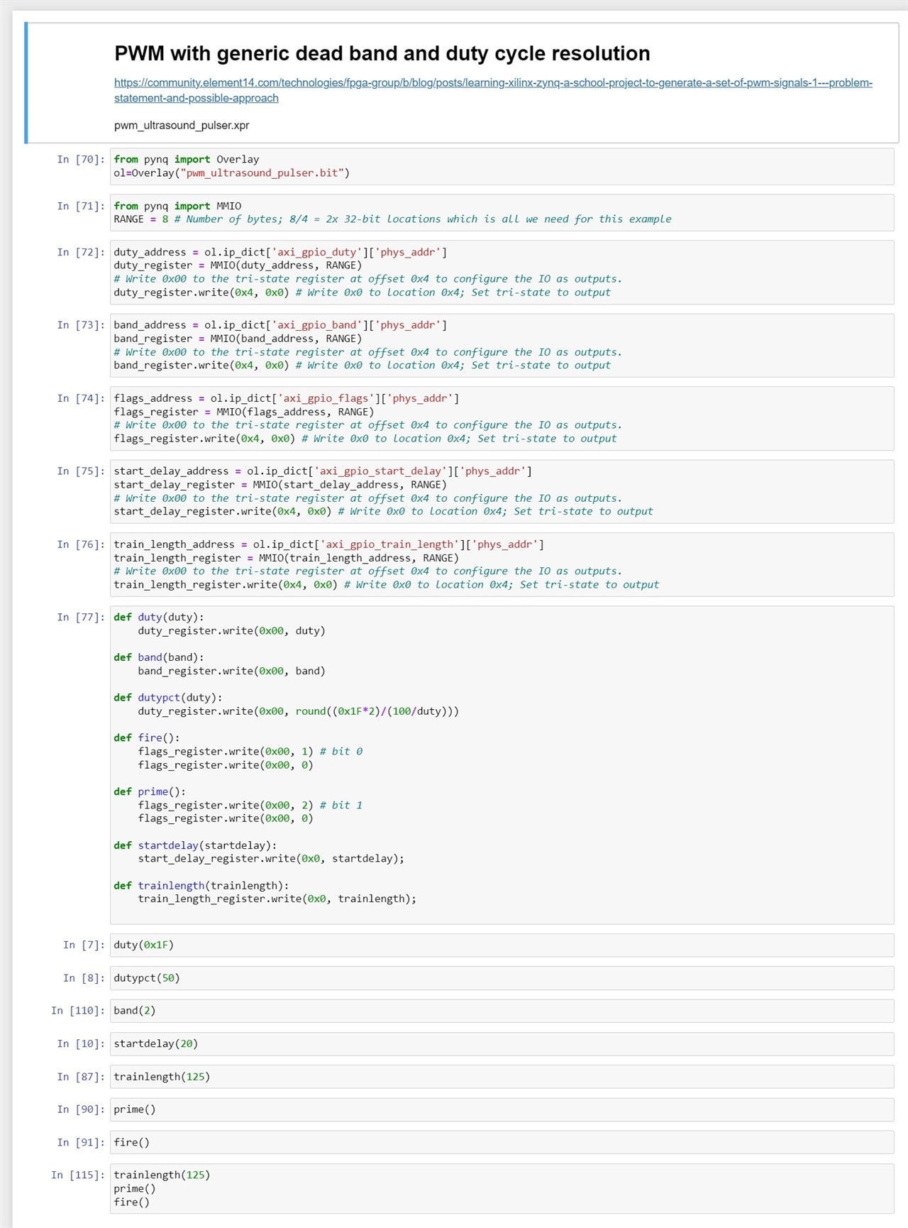
Jupyter:

image

Jupyter source:

{
 "cells": [
  {
   "cell_type": "markdown",
   "metadata": {},
   "source": [
    "# PWM with generic dead band and duty cycle resolution\n",
    "\n",
    "https://community.element14.com/technologies/fpga-group/b/blog/posts/learning-xilinx-zynq-a-school-project-to-generate-a-set-of-pwm-signals-1---problem-statement-and-possible-approach\n",
    "\n",
    "pwm_ultrasound_pulser.xpr"
   ]
  },
  {
   "cell_type": "code",
   "execution_count": 70,
   "metadata": {},
   "outputs": [],
   "source": [
    "from pynq import Overlay\n",
    "ol=Overlay(\"pwm_ultrasound_pulser.bit\")"
   ]
  },
  {
   "cell_type": "code",
   "execution_count": 71,
   "metadata": {},
   "outputs": [],
   "source": [
    "from pynq import MMIO\n",
    "RANGE = 8 # Number of bytes; 8/4 = 2x 32-bit locations which is all we need for this example"
   ]
  },
  {
   "cell_type": "code",
   "execution_count": 72,
   "metadata": {},
   "outputs": [],
   "source": [
    "duty_address = ol.ip_dict['axi_gpio_duty']['phys_addr']\n",
    "duty_register = MMIO(duty_address, RANGE) \n",
    "# Write 0x00 to the tri-state register at offset 0x4 to configure the IO as outputs.\n",
    "duty_register.write(0x4, 0x0) # Write 0x0 to location 0x4; Set tri-state to output"
   ]
  },
  {
   "cell_type": "code",
   "execution_count": 73,
   "metadata": {},
   "outputs": [],
   "source": [
    "band_address = ol.ip_dict['axi_gpio_band']['phys_addr']\n",
    "band_register = MMIO(band_address, RANGE) \n",
    "# Write 0x00 to the tri-state register at offset 0x4 to configure the IO as outputs.\n",
    "band_register.write(0x4, 0x0) # Write 0x0 to location 0x4; Set tri-state to output"
   ]
  },
  {
   "cell_type": "code",
   "execution_count": 74,
   "metadata": {},
   "outputs": [],
   "source": [
    "flags_address = ol.ip_dict['axi_gpio_flags']['phys_addr']\n",
    "flags_register = MMIO(flags_address, RANGE) \n",
    "# Write 0x00 to the tri-state register at offset 0x4 to configure the IO as outputs.\n",
    "flags_register.write(0x4, 0x0) # Write 0x0 to location 0x4; Set tri-state to output"
   ]
  },
  {
   "cell_type": "code",
   "execution_count": 75,
   "metadata": {},
   "outputs": [],
   "source": [
    "start_delay_address = ol.ip_dict['axi_gpio_start_delay']['phys_addr']\n",
    "start_delay_register = MMIO(start_delay_address, RANGE) \n",
    "# Write 0x00 to the tri-state register at offset 0x4 to configure the IO as outputs.\n",
    "start_delay_register.write(0x4, 0x0) # Write 0x0 to location 0x4; Set tri-state to output"
   ]
  },
  {
   "cell_type": "code",
   "execution_count": 76,
   "metadata": {},
   "outputs": [],
   "source": [
    "train_length_address = ol.ip_dict['axi_gpio_train_length']['phys_addr']\n",
    "train_length_register = MMIO(train_length_address, RANGE) \n",
    "# Write 0x00 to the tri-state register at offset 0x4 to configure the IO as outputs.\n",
    "train_length_register.write(0x4, 0x0) # Write 0x0 to location 0x4; Set tri-state to output"
   ]
  },
  {
   "cell_type": "code",
   "execution_count": 77,
   "metadata": {},
   "outputs": [],
   "source": [
    "def duty(duty):\n",
    "    duty_register.write(0x00, duty)\n",
    "    \n",
    "def band(band):\n",
    "    band_register.write(0x00, band)\n",
    "    \n",
    "def dutypct(duty):\n",
    "    duty_register.write(0x00, round((0x1F*2)/(100/duty)))\n",
    "    \n",
    "def fire():\n",
    "    flags_register.write(0x00, 1) # bit 0\n",
    "    flags_register.write(0x00, 0)\n",
    "\n",
    "def prime():\n",
    "    flags_register.write(0x00, 2) # bit 1\n",
    "    flags_register.write(0x00, 0)\n",
    "    \n",
    "def startdelay(startdelay):\n",
    "    start_delay_register.write(0x0, startdelay);\n",
    "\n",
    "def trainlength(trainlength):\n",
    "    train_length_register.write(0x0, trainlength);\n"
   ]
  },
  {
   "cell_type": "code",
   "execution_count": 7,
   "metadata": {},
   "outputs": [],
   "source": [
    "duty(0x1F)"
   ]
  },
  {
   "cell_type": "code",
   "execution_count": 8,
   "metadata": {},
   "outputs": [],
   "source": [
    "dutypct(50)"
   ]
  },
  {
   "cell_type": "code",
   "execution_count": 110,
   "metadata": {},
   "outputs": [],
   "source": [
    "band(2)"
   ]
  },
  {
   "cell_type": "code",
   "execution_count": 10,
   "metadata": {},
   "outputs": [],
   "source": [
    "startdelay(20)"
   ]
  },
  {
   "cell_type": "code",
   "execution_count": 87,
   "metadata": {},
   "outputs": [],
   "source": [
    "trainlength(125)"
   ]
  },
  {
   "cell_type": "code",
   "execution_count": 90,
   "metadata": {},
   "outputs": [],
   "source": [
    "prime()"
   ]
  },
  {
   "cell_type": "code",
   "execution_count": 91,
   "metadata": {},
   "outputs": [],
   "source": [
    "fire()"
   ]
  },
  {
   "cell_type": "code",
   "execution_count": 115,
   "metadata": {},
   "outputs": [],
   "source": [
    "trainlength(125)\n",
    "prime()\n",
    "fire()"
   ]
  }
 ],
 "metadata": {
  "kernelspec": {
   "display_name": "Python 3 (ipykernel)",
   "language": "python",
   "name": "python3"
  },
  "language_info": {
   "codemirror_mode": {
    "name": "ipython",
    "version": 3
   },
   "file_extension": ".py",
   "mimetype": "text/x-python",
   "name": "python",
   "nbconvert_exporter": "python",
   "pygments_lexer": "ipython3",
   "version": "3.10.4"
  }
 },
 "nbformat": 4,
 "nbformat_minor": 2
}

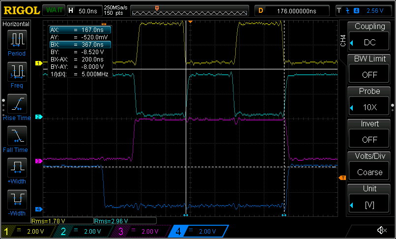
Scope capture (PWM, PWMN, PULSE, PRF)

0 dead time:
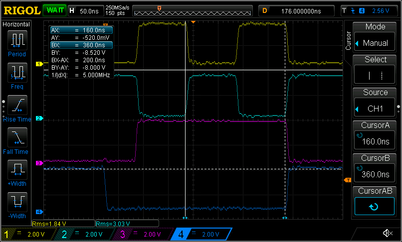
image

2 dead time:
image

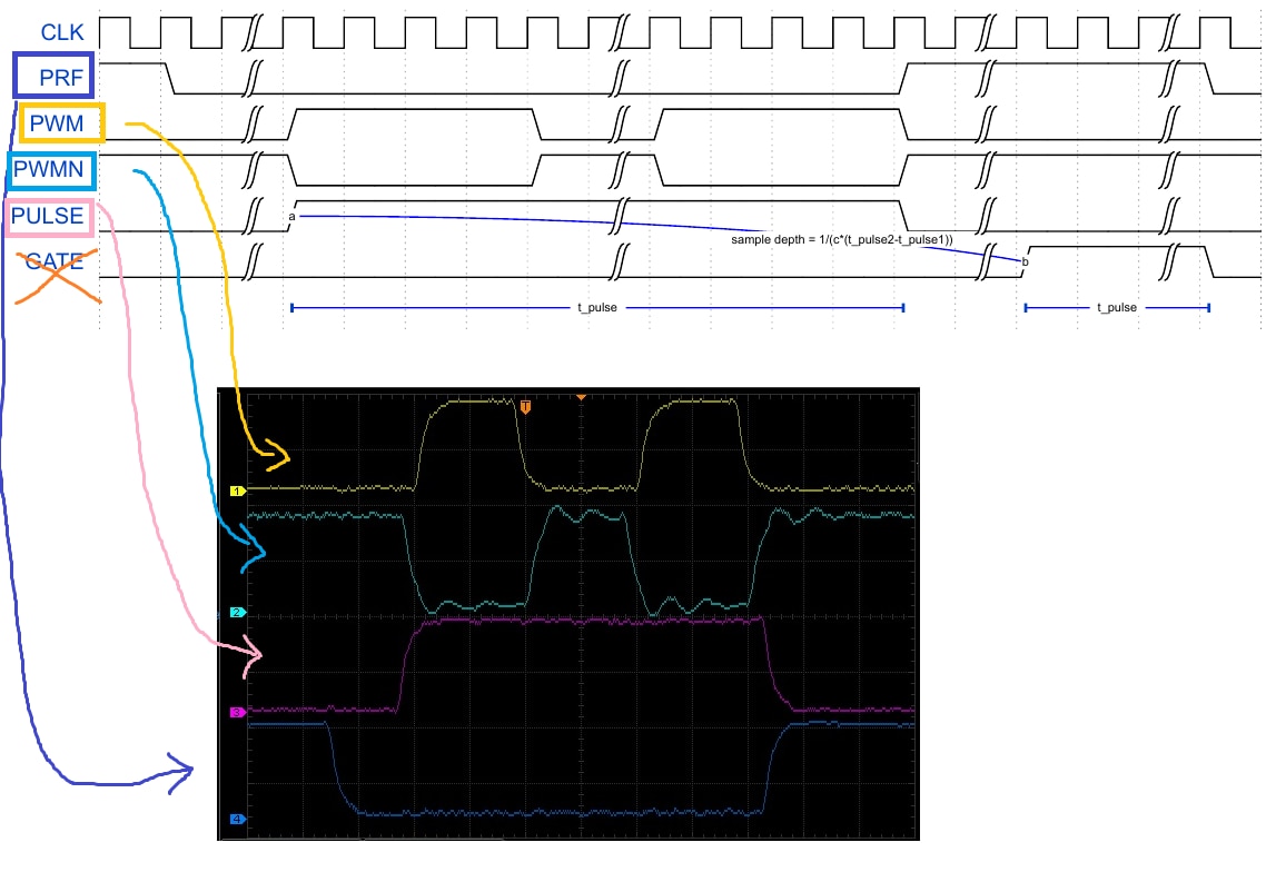
Compare to requirement:

image

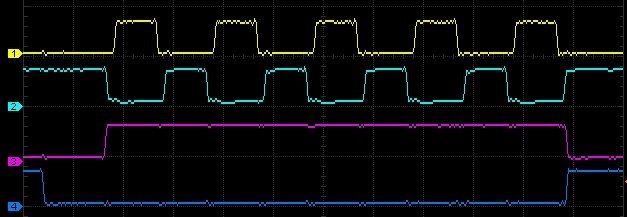
Example with longer initial delay and a longer pulse train, 5 pulses of dead band. The FPGA design is the same. This is done by writing different values to the registers:
image

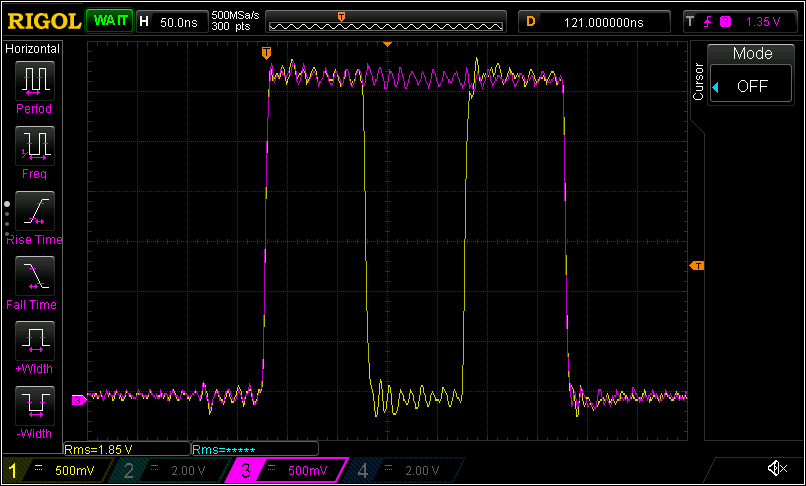
Study of the edges. You see the PWM and PULSE signal, 0 dead band.
image

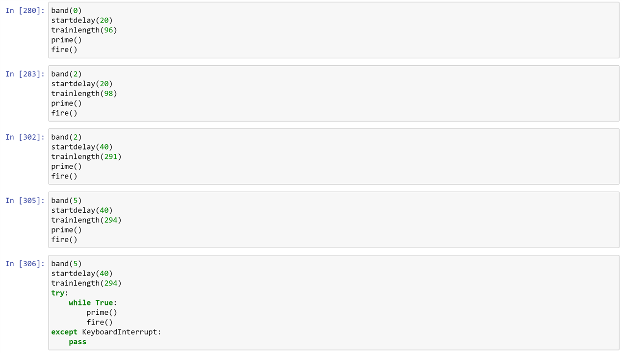
A few example settings that generate complete pulses. The first two generate 2 pulses, with a short start delay. The second 2 have a longer start delay and generate 5 pulses. The last one is retriggered in a software loop. I've also played with the deadbands.
image

Vivado project and Jupyter notebook are attached. They are for version 2022.1 and PYNQ-Z2 board
pwm_ultrasound_pulser_and_jupyter_20230506.zip

link to all posts.

  • Sign in to reply

Top Comments

  • Jan Cumps
    Jan Cumps over 2 years ago +1
    test of using a control block, that generates a PULSE signal and controls the pulse train:
  • Jan Cumps
    Jan Cumps over 2 years ago in reply to yepe +1
    The Pulse, Gate and PMW(n) can all be specified as number of CLK pulses. Pulse and PWM(n) have to be active atthe same time' for the same time. Gate hasto be active for the same time, but after a delay…
  • Jan Cumps
    Jan Cumps over 2 years ago in reply to yepe +1
    After running Synthesis, open the synthesis design. Then, you should have access to a IO window (not at my pc at the moment, but I think it's under the Windows menu. There you have to define to what…
Parents
  • yepe
    yepe over 2 years ago

    I am following along trying to implement the design on my end. I created the following block diagram with the Pwm.vhd file from your last post

    image

    Synthesis and implementation completes, but generating the bitstream fails. Maybe I did something wrong in the block diagram or in the customization of the blocks? Or maybe I am lacking a constraint file? The internal mechanisms of the AXI interconnects are a bit of a mystery for me Smiley

    Command: write_bitstream -force Pwm.bit
    Attempting to get a license for feature 'Implementation' and/or device 'xc7z020'
    INFO: [Common 17-349] Got license for feature 'Implementation' and/or device 'xc7z020'
    Running DRC as a precondition to command write_bitstream
    INFO: [IP_Flow 19-234] Refreshing IP repositories
    INFO: [IP_Flow 19-1704] No user IP repositories specified
    INFO: [IP_Flow 19-2313] Loaded Vivado IP repository 'C:/Xilinx/Vivado/2022.2/data/ip'.
    INFO: [DRC 23-27] Running DRC with 2 threads
    ERROR: [DRC NSTD-1] Unspecified I/O Standard: 15 out of 15 logical ports use I/O standard (IOSTANDARD) value 'DEFAULT', instead of a user assigned specific value. This may cause I/O contention or incompatibility with the board power or connectivity affecting performance, signal integrity or in extreme cases cause damage to the device or the components to which it is connected. To correct this violation, specify all I/O standards. This design will fail to generate a bitstream unless all logical ports have a user specified I/O standard value defined. To allow bitstream creation with unspecified I/O standard values (not recommended), use this command: set_property SEVERITY {Warning} [get_drc_checks NSTD-1].  NOTE: When using the Vivado Runs infrastructure (e.g. launch_runs Tcl command), add this command to a .tcl file and add that file as a pre-hook for write_bitstream step for the implementation run. Problem ports: band_i[3:0], duty_i[5:0], clk_i, enable_i, n_reset_i, pwmA_o, and pwmB_o.
    ERROR: [DRC UCIO-1] Unconstrained Logical Port: 15 out of 15 logical ports have no user assigned specific location constraint (LOC). This may cause I/O contention or incompatibility with the board power or connectivity affecting performance, signal integrity or in extreme cases cause damage to the device or the components to which it is connected. To correct this violation, specify all pin locations. This design will fail to generate a bitstream unless all logical ports have a user specified site LOC constraint defined.  To allow bitstream creation with unspecified pin locations (not recommended), use this command: set_property SEVERITY {Warning} [get_drc_checks UCIO-1].  NOTE: When using the Vivado Runs infrastructure (e.g. launch_runs Tcl command), add this command to a .tcl file and add that file as a pre-hook for write_bitstream step for the implementation run.  Problem ports: band_i[3:0], duty_i[5:0], clk_i, enable_i, n_reset_i, pwmA_o, and pwmB_o.
    WARNING: [DRC ZPS7-1] PS7 block required: The PS7 cell must be used in this Zynq design in order to enable correct default configuration.
    INFO: [Vivado 12-3199] DRC finished with 2 Errors, 1 Warnings
    INFO: [Vivado 12-3200] Please refer to the DRC report (report_drc) for more information.
    ERROR: [Vivado 12-1345] Error(s) found during DRC. Bitgen not run.
    INFO: [Common 17-83] Releasing license: Implementation
    15 Infos, 1 Warnings, 0 Critical Warnings and 3 Errors encountered.
    write_bitstream failed
    ERROR: [Common 17-39] 'write_bitstream' failed due to earlier errors.

    Looking at the log, it seems to be related to IO

    • Cancel
    • Vote Up 0 Vote Down
    • Sign in to reply
    • More
    • Cancel
  • Jan Cumps
    Jan Cumps over 2 years ago in reply to yepe

    After running Synthesis, open the synthesis design.

    Then, you should have access to a IO window (not at my pc at the moment, but I think it's under the Windows menu.

    There you have to define to what FPGA ball each external signalhas to connect.

    Double-checkif you generated a wrapper for the board design, and that yo've set that wrapper as the Top of the design. I tend to forget that Slight smile, and then get implementation errors....

    • Cancel
    • Vote Up +1 Vote Down
    • Sign in to reply
    • More
    • Cancel
  • yepe
    yepe over 2 years ago in reply to Jan Cumps

    Neat! I will give the script a go. Thanks!

    • Cancel
    • Vote Up 0 Vote Down
    • Sign in to reply
    • More
    • Cancel
  • Jan Cumps
    Jan Cumps over 2 years ago in reply to yepe

    Open the .HWH file in a text editor, and search for /axi_gpio_

    There should be an occurence for each AXI_GPIO on the board design.

    That's the info that PYNQ uses to build up its dictionary of objects.

    • Cancel
    • Vote Up 0 Vote Down
    • Sign in to reply
    • More
    • Cancel
  • yepe
    yepe over 2 years ago in reply to Jan Cumps

    I had a look in the hwh file and I could find all of the objects in the contents of pwm_pulser.hwh. I have re-run the synthesis, implementation runs, etc. All had the same result. One thing I noticed is a persistent error in Vivado:

    image

    Could this cause Jupyter to not be able to find all the AXI GPIO objects?

    • Cancel
    • Vote Up 0 Vote Down
    • Sign in to reply
    • More
    • Cancel
  • Jan Cumps
    Jan Cumps over 2 years ago in reply to yepe

    Check in the constraints source file if there are left-over entries from old connections.

    It should only contain external definitions. In my case:

    image

    • Cancel
    • Vote Up 0 Vote Down
    • Sign in to reply
    • More
    • Cancel
  • yepe
    yepe over 2 years ago in reply to Jan Cumps

    These are the contents I have at the moment

    image

    Yet the error persists. Or could it be something wrong in my block diagram?

    • Cancel
    • Vote Up 0 Vote Down
    • Sign in to reply
    • More
    • Cancel
Comment
  • yepe
    yepe over 2 years ago in reply to Jan Cumps

    These are the contents I have at the moment

    image

    Yet the error persists. Or could it be something wrong in my block diagram?

    • Cancel
    • Vote Up 0 Vote Down
    • Sign in to reply
    • More
    • Cancel
Children
  • Jan Cumps
    Jan Cumps over 2 years ago in reply to yepe

    I have not seen this error before.

    I've seen one thing in your design that's not correct: axi_gpio_band has a 78 bit output connected to a 4 bit input.
    You need to limit the output bits of the axi_gpio block.

    image

    But that's not the error you get. You get errors about a gpio block that's not on the board. Maybe the old name.

    Can you go to Project Manager -> Settings -> Project -> IP, and clear the IP cache? Then try again?

    image

    • Cancel
    • Vote Up 0 Vote Down
    • Sign in to reply
    • More
    • Cancel
  • Jan Cumps
    Jan Cumps over 2 years ago in reply to Jan Cumps

    your output files seem to be named pwm_pulser.*. If you haven't renamed them before loading to the PYNQ, you have to change the first Jupyter block.

    From:

    image

    to 

    ol = Overlay("pwm_pulser.bit")

    If you use my tcl script, the work of giving both .bit and .hwh the same name (your project name) has already been done. The Jupyter code has to use that name.

    • Cancel
    • Vote Up 0 Vote Down
    • Sign in to reply
    • More
    • Cancel
element14 Community

element14 is the first online community specifically for engineers. Connect with your peers and get expert answers to your questions.

  • Members
  • Learn
  • Technologies
  • Challenges & Projects
  • Products
  • Store
  • About Us
  • Feedback & Support
  • FAQs
  • Terms of Use
  • Privacy Policy
  • Legal and Copyright Notices
  • Sitemap
  • Cookies

An Avnet Company © 2025 Premier Farnell Limited. All Rights Reserved.

Premier Farnell Ltd, registered in England and Wales (no 00876412), registered office: Farnell House, Forge Lane, Leeds LS12 2NE.

ICP 备案号 10220084.

Follow element14

  • X
  • Facebook
  • linkedin
  • YouTube