Sometimes the hardware module development could be more complex than expected. A way to solve it is using a General-Purpose Computing Architecture to solve some data transfers and processing by software. In this case, let's develop a 4-bit counter to illustrate a counting solution. the first step is develop a base architecture like the following:

This architecture requires a small configuration using Block Design. The MicroBlaze could be configured as the application needs. I used the defaults, with 32 bits word length and performance optimization with 8KB of memory. The Clocking Wizard requires an Active Low Reset Type to make direct compatibility with the Processor System Reset. An important factor in this system is establishing communications. To achieve this an AXI Uartlite IP Block is added. This Block is configured with a Baud Rate of 115200 for fast communication and compatibility with common peripherals. In addition, two GPIO Blocks are added: One for the 4-bit LEDs and the other one, in dual channel configuration, for Dip Switches. The default template has no small rule for the Dip Switches definition, this brings a Bitstream generation issue. To solve this, an additional XDC file is required with the following constraint:
set_property INTERNAL_VREF 0.675 [get_iobanks 34]
An Address map can be viewed with the graphical tool available in Vivado.
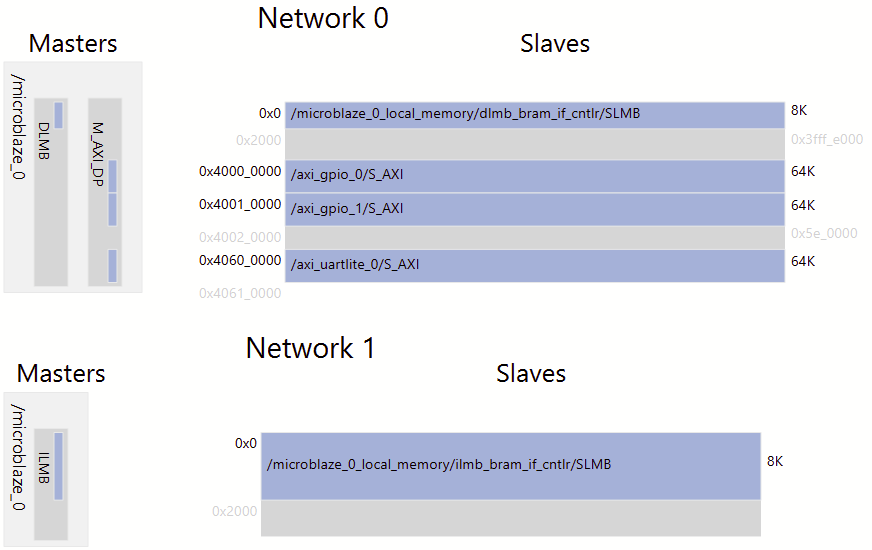
Finally, we have an architecture that could be compared with other commercially available microcontrollers (uC). The first difference is the huge flexibility of the platform compared with ASIC or uC containing fixed components.
This is the first step, but a well-defined hardware architecture requires software to operate. Vivado includes Vitis IDE to develop software architecture for a specific hardware MicroBlaze-based architecture designed. According to the "Hello world" application, the developed software is the next:
#include <stdio.h>
#include <stdint.h>
#include "platform.h"
#include "xil_printf.h"
#include "sleep.h"
#include "GPIO.h"

IP_GPIO_t volatile *const LEDS = (IP_GPIO_t*)XPAR_AXI_GPIO_0_BASEADDR;
IP_GPIO_t volatile *const INPUTS = (IP_GPIO_t*)XPAR_AXI_GPIO_1_BASEADDR;

int main(void){
    init_platform();

    print("Hello World\n\r");
    print("Successfully ran Hello World application\n\r");
    LEDS -> TRI1 = 0x00000000;
    uint8_t Q = 0;
    while(1){
    	if(!(INPUTS -> DATA1 & 0b0001)){
    		if(INPUTS -> DATA1 & 0b0010){
    			Q = INPUTS -> DATA2;
    		}else{
				if(INPUTS -> DATA1 & 0b0100){
					Q++;
				}else{
					Q--;
				}
    		}
    	}
    	LEDS -> DATA1 = Q;
    	sleep(1);
    }
    cleanup_platform();
    return 0;
}
As you can see, a 4-bit counter is implemented with Reset, Load, and blocking control like the last implementation in my comparative available in From 6 to 7 series. A comparative approach blog. The declaration IP_GPIO_t volatile *const allow an unoptimized variable access, this brings a direct register lecture while a non-volatile variable read the register and retains it, if any change is made during the next register access, this will not be detected. In addition, constant memory address blocks the address redefinition to the pointer, avoiding programmer mapping risks.
But, how the IP_GPIO_t is implemented? According to the Product Guide, available in Vivado too, the Register Space of the AXI GPIO v2.0 is shown below,
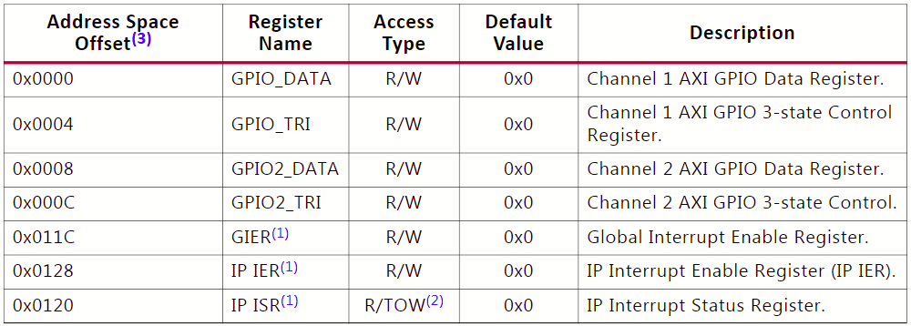
with this in mind, we can declare the new data type like,
#include<stdint.h>

typedef struct{
	uint32_t DATA1;
	uint32_t TRI1;
	uint32_t DATA2;
	uint32_t TRI2;
	uint32_t GIER;
	uint32_t IER;
	uint32_t ISR;
}IP_GPIO_t;
This allows to memory addresses to control configuration and data access in a Bare metal way, but the Hardware Abstraction Layer (HAL) is available too. The resource consumption at this moment is the following,
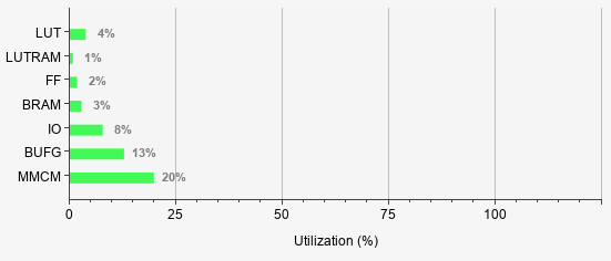
We have a lot of resources available to add new features to the architecture.
Thanks to jugal for his assistance in solving the io_bank issue. cbohra00627, here is my new base project. I am adding new features to solve my proposal and bring other point-of-view about the tools usage.
Do you want to follow this project? You can do it. I caught the TCL commands and I created a base TCL script to build the updated platform. The implemented little endian 32-bit MicroBlaze-based platform can be created from the following script,
set BASE_PATH D:/VitisProjects/MicroBlazeControl
create_project MicroBlazeControl $BASE_PATH -part xc7s50csga324-1
set_property board_part digilentinc.com:arty-s7-50:part0:1.0 [current_project]
cd $BASE_PATH

create_bd_design "ControlArch"
update_compile_order -fileset sources_1

startgroup
create_bd_cell -type ip -vlnv xilinx.com:ip:microblaze:11.0 CPU_0
endgroup

apply_bd_automation -rule xilinx.com:bd_rule:microblaze -config { axi_intc {0} axi_periph {Enabled} cache {None} clk {New Clocking Wizard} cores {1} debug_module {Debug Only} ecc {None} local_mem {128KB} preset {None}}  [get_bd_cells CPU_0]

startgroup
create_bd_cell -type ip -vlnv xilinx.com:ip:axi_uartlite:2.0 UARTLITE_0
endgroup
set_property -dict [list CONFIG.C_BAUDRATE {115200} CONFIG.UARTLITE_BOARD_INTERFACE {usb_uart}] [get_bd_cells UARTLITE_0]

startgroup
create_bd_cell -type ip -vlnv xilinx.com:ip:axi_gpio:2.0 GPIO_0
endgroup
set_property -dict [list CONFIG.C_GPIO_WIDTH {4} CONFIG.C_GPIO2_WIDTH {6} CONFIG.C_IS_DUAL {1} CONFIG.GPIO_BOARD_INTERFACE {led_4bits} CONFIG.GPIO2_BOARD_INTERFACE {rgb_led} CONFIG.C_ALL_OUTPUTS {1} CONFIG.C_ALL_OUTPUTS_2 {1}] [get_bd_cells GPIO_0]
startgroup
create_bd_cell -type ip -vlnv xilinx.com:ip:axi_gpio:2.0 GPIO_1
endgroup
set_property -dict [list CONFIG.C_GPIO_WIDTH {4} CONFIG.C_GPIO2_WIDTH {4} CONFIG.C_IS_DUAL {1} CONFIG.C_ALL_INPUTS {1} CONFIG.C_ALL_INPUTS_2 {1} CONFIG.GPIO_BOARD_INTERFACE {dip_switches_4bits} CONFIG.GPIO2_BOARD_INTERFACE {push_buttons_4bits}] [get_bd_cells GPIO_1]

startgroup
set_property -dict [list CONFIG.CLK_IN1_BOARD_INTERFACE {sys_clock} CONFIG.USE_LOCKED {false} CONFIG.RESET_TYPE {ACTIVE_LOW} CONFIG.PRIM_SOURCE {Single_ended_clock_capable_pin} CONFIG.CLKIN1_JITTER_PS {833.33} CONFIG.MMCM_CLKFBOUT_MULT_F {62.500} CONFIG.MMCM_CLKIN1_PERIOD {83.333} CONFIG.MMCM_CLKIN2_PERIOD {10.0} CONFIG.MMCM_CLKOUT0_DIVIDE_F {7.500} CONFIG.RESET_PORT {resetn} CONFIG.CLKOUT1_JITTER {479.872} CONFIG.CLKOUT1_PHASE_ERROR {668.310}] [get_bd_cells clk_wiz_1]
delete_bd_objs [get_bd_nets clk_wiz_1_locked]
endgroup

startgroup
apply_bd_automation -rule xilinx.com:bd_rule:board -config { Board_Interface {led_4bits ( 4 LEDs ) } Manual_Source {Auto}}  [get_bd_intf_pins GPIO_0/GPIO]
apply_bd_automation -rule xilinx.com:bd_rule:board -config { Board_Interface {rgb_led ( 2 RGB LEDS ) } Manual_Source {Auto}}  [get_bd_intf_pins GPIO_0/GPIO2]
apply_bd_automation -rule xilinx.com:bd_rule:axi4 -config { Clk_master {/clk_wiz_1/clk_out1 (100 MHz)} Clk_slave {Auto} Clk_xbar {Auto} Master {/CPU_0 (Periph)} Slave {/GPIO_0/S_AXI} ddr_seg {Auto} intc_ip {New AXI Interconnect} master_apm {0}}  [get_bd_intf_pins GPIO_0/S_AXI]
apply_bd_automation -rule xilinx.com:bd_rule:board -config { Board_Interface {dip_switches_4bits ( 4 Switches ) } Manual_Source {Auto}}  [get_bd_intf_pins GPIO_1/GPIO]
apply_bd_automation -rule xilinx.com:bd_rule:board -config { Board_Interface {push_buttons_4bits ( 4 Push Buttons ) } Manual_Source {Auto}}  [get_bd_intf_pins GPIO_1/GPIO2]
apply_bd_automation -rule xilinx.com:bd_rule:axi4 -config { Clk_master {/clk_wiz_1/clk_out1 (100 MHz)} Clk_slave {Auto} Clk_xbar {Auto} Master {/CPU_0 (Periph)} Slave {/GPIO_1/S_AXI} ddr_seg {Auto} intc_ip {New AXI Interconnect} master_apm {0}}  [get_bd_intf_pins GPIO_1/S_AXI]
apply_bd_automation -rule xilinx.com:bd_rule:axi4 -config { Clk_master {/clk_wiz_1/clk_out1 (100 MHz)} Clk_slave {Auto} Clk_xbar {Auto} Master {/CPU_0 (Periph)} Slave {/UARTLITE_0/S_AXI} ddr_seg {Auto} intc_ip {New AXI Interconnect} master_apm {0}}  [get_bd_intf_pins UARTLITE_0/S_AXI]
apply_bd_automation -rule xilinx.com:bd_rule:board -config { Board_Interface {usb_uart ( USB UART ) } Manual_Source {Auto}}  [get_bd_intf_pins UARTLITE_0/UART]
apply_bd_automation -rule xilinx.com:bd_rule:board -config { Board_Interface {sys_clock ( System Clock ) } Manual_Source {Auto}}  [get_bd_pins clk_wiz_1/clk_in1]
apply_bd_automation -rule xilinx.com:bd_rule:board -config { Board_Interface {reset ( System Reset ) } Manual_Source {New External Port (ACTIVE_LOW)}}  [get_bd_pins clk_wiz_1/resetn]
apply_bd_automation -rule xilinx.com:bd_rule:board -config { Board_Interface {reset ( System Reset ) } Manual_Source {Auto}}  [get_bd_pins rst_clk_wiz_1_100M/ext_reset_in]
endgroup

regenerate_bd_layout
save_bd_design

make_wrapper -files [get_files ./MicroBlazeControl.srcs/sources_1/bd/ControlArch/ControlArch.bd] -top
add_files -norecurse ./MicroBlazeControl.gen/sources_1/bd/ControlArch/hdl/ControlArch_wrapper.v

file mkdir ./MicroBlazeControl.srcs/constrs_1
file mkdir ./MicroBlazeControl.srcs/constrs_1/new
set constraint [open ./MicroBlazeControl.srcs/constrs_1/new/Additional.xdc w]
puts $constraint "set_property INTERNAL_VREF 0.675 \[get_iobanks 34\]"
close $constraint
add_files -fileset constrs_1 ./MicroBlazeControl.srcs/constrs_1/new/Additional.xdc

launch_runs impl_1 -to_step write_bitstream -jobs 4
wait_on_run impl_1
write_hw_platform -fixed -include_bit -force -file ./ControlArch_wrapper.xsa
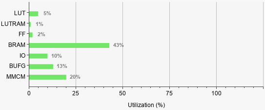
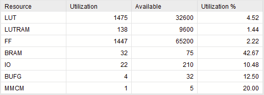
This script includes the addition of the missing constraint, you only need to change the BASE_PATH to configure your working directory. The memory was updated to 128 KB, consequently, the BRAM utilization increased to 42.67% and the LUTs required to memory addressing had a minimal additions. I added the RGB leds, this brought more IO requirements too.
Finally, the codes required are the following to obtain a meaningful 4-bit counter implementation in a structured way,
GPIO.h
#ifndef __GPIO_H__
#define __GPIO_H__

#include<stdint.h>

typedef struct{
	uint32_t DATA1;
	uint32_t TRI1;
	uint32_t DATA2;
	uint32_t TRI2;
	uint32_t GIER;
	uint32_t IER;
	uint32_t ISR;
}IP_GPIO_t;

#endif
helloworld.c
#include <stdio.h>
#include <stdint.h>
#include "platform.h"
#include "xil_printf.h"
#include "sleep.h"
#include "GPIO.h"

IP_GPIO_t volatile *const LEDS = (IP_GPIO_t*)XPAR_GPIO_0_BASEADDR;
IP_GPIO_t volatile *const INPUTS = (IP_GPIO_t*)XPAR_GPIO_1_BASEADDR;

typedef struct{
	uint32_t value: 4;
}nibble_t;

int main(void){
    init_platform();
    LEDS -> TRI1 = 0x00000000;
    nibble_t Q = {0};
    while(1){
    	if(!(INPUTS -> DATA2 & 0b0001)){
    		if(INPUTS -> DATA2 & 0b0010){
    			Q.value = INPUTS -> DATA1;
    		}else{
				if(INPUTS -> DATA2 & 0b0100){
					Q.value++;
				}else{
					Q.value--;
				}
    		}
    	}
    	xil_printf("%02d\n", Q.value);
    	LEDS -> DATA1 = Q.value;
    	sleep(1);
    }
    cleanup_platform();
    return 0;
}