


Part 2 of a little double post to document the porting of a small FPGA design from a Zynq with ARM + Linux + Pynq + Python to a smaller Spartan with MicroBlaze soft controller + bare metal.
In post 1, I show the Vivado design differences. Zynq uses the hard-silicon ARM microcontroller to run the software components. On Spartan-7 I use a MicroBlaze soft microcontroller core ,implemented in the FPGA fabric.
The software part of this design is very simple. The only things that the software needs to do are:
- send configuration values to the VHDL components. These values will be used in those components to define the signals it generates. See Learning AMD Zynq: a project to generate a set of PWM signals. 1 - problem statement and possible approach . These don't need a user interface, can be defined as constants, defaults, ...
- send prime and fire signals the VHDL signal controller.
- listen to some user input method to send those 2 signals.
Comparison:
| Spartan-7 | Zynq with Pynq | |
| core | MicroBlaze soft microcontroller core implemented in part of the FPGA fabric | real ARM Microprocessor on the same silicon as the FPGA fabric |
| software stack | bare metal, C, and AMD HAL for FPGA IPs and MicroBlaze-FPGA interfaces | Linux OS, PYNQ python wrapper around FPGA IPs and ARM-FPGA interfaces, and Jupyter web service to run user Python code |
| software-FPGA interface | memory mapped AXI GPIO IP | memory mapped AXI GPIO IP |
| development tool | Vitis C IDE | Jupyter web server that runs user Python code |
| Deploy | Bitstream with C program loaded into FPGA fabric (or Flash) as usual (e.g. Vivado hardware manager or Vitis FPGA programmer. | Linux with PYNQ run from SD card. Bitstream and user code loaded into fabric via a Jupyter web page, or PYNQ directly |
| Set the VHDL registers | Write to a memory location (AXI GPIO) via C code | Write to a memory location (AXI GPIO) via Python, in a Jupyter notebook |
| receive user Trigger and Fire command | user buttons polled by the Microblaze firmware. The firmware writes to the VHDL (via AXI GPIO) trigger and fire flags | Execute a Python command to write to the VHDL (via AXI GPIO trigger and fire flags) using a Jupyter notebook. |
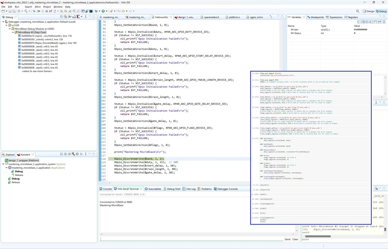
Spartan-7 C software in Vitis
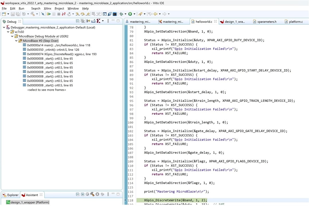
The software runs on the MicroBlaze soft-microcontroller-core implemented with components of the FPGA fabric. Just like your VHDL code, it consumes gates, flip-flops, LUTs, .... of the Spartan. You write traditional microcontroller C firmware for that Microblaze, in the Vitis (Eclipse) IDE.
Drivers and configuration for the AXI GPIO registers (and other hardware designed in Vivado) are generated for you. You use Vitis HAL C APIs to interact. For the firmware developer, it feels as if you develop for a microcontroller, and the VHDL blocks are peripherals, like UART, I2C, SPI. Reading button states is reading a memory mapped register. Writing to the VHDL blocks is writing to a memory mapped location. Just like writing to (e.g. timer) registers for an ATMega controller.
#include <stdio.h>
#include "platform.h"
#include "xil_printf.h"
#include "xparameters.h"
#include "xgpio.h"
#include "xil_io.h"

XGpio inputz, band, duty, start_delay, train_length, gate_delay, flagz;

int main()
{
	uint32_t btn;

	int Status;


	init_platform();

//	/* Initialize the GPIO driver */
//	Status = XGpio_Initialize(&inputz, XPAR_AXI_GPIO_INPUT_DEVICE_ID);
//	if (Status != XST_SUCCESS) {
//		xil_printf("Gpio Initialization Failed\r\n");
//		return XST_FAILURE;
//	}
//	XGpio_SetDataDirection(&inputz, 1, 15); // buttons are bit 0 and 1, they are inputs
//
	Status = XGpio_Initialize(&band, XPAR_AXI_GPIO_BAND_DEVICE_ID);
	if (Status != XST_SUCCESS) {
		xil_printf("Gpio Initialization Failed\r\n");
		return XST_FAILURE;
	}
	XGpio_SetDataDirection(&band, 1, 0);

	Status = XGpio_Initialize(&duty, XPAR_AXI_GPIO_DUTY_DEVICE_ID);
	if (Status != XST_SUCCESS) {
		xil_printf("Gpio Initialization Failed\r\n");
		return XST_FAILURE;
	}
	XGpio_SetDataDirection(&duty, 1, 0);

	Status = XGpio_Initialize(&start_delay, XPAR_AXI_GPIO_START_DELAY_DEVICE_ID);
	if (Status != XST_SUCCESS) {
		xil_printf("Gpio Initialization Failed\r\n");
		return XST_FAILURE;
	}
	XGpio_SetDataDirection(&start_delay, 1, 0);

	Status = XGpio_Initialize(&train_length, XPAR_AXI_GPIO_TRAIN_LENGTH_DEVICE_ID);
	if (Status != XST_SUCCESS) {
		xil_printf("Gpio Initialization Failed\r\n");
		return XST_FAILURE;
	}
	XGpio_SetDataDirection(&train_length, 1, 0);

	Status = XGpio_Initialize(&gate_delay, XPAR_AXI_GPIO_GATE_DELAY_DEVICE_ID);
	if (Status != XST_SUCCESS) {
		xil_printf("Gpio Initialization Failed\r\n");
		return XST_FAILURE;
	}
	XGpio_SetDataDirection(&gate_delay, 1, 0);

	Status = XGpio_Initialize(&flagz, XPAR_AXI_GPIO_FLAGS_DEVICE_ID);
	if (Status != XST_SUCCESS) {
		xil_printf("Gpio Initialization Failed\r\n");
		return XST_FAILURE;
	}
	XGpio_SetDataDirection(&flagz, 1, 0);

	print("Mastering MicroBlaze\n\r");

	XGpio_DiscreteWrite(&band, 1, 2);
	XGpio_DiscreteWrite(&duty, 1, 15);  // 50%
	XGpio_DiscreteWrite(&start_delay, 1, 20);
	XGpio_DiscreteWrite(&train_length, 1, 98);
	XGpio_DiscreteWrite(&gate_delay, 1, 20);


   	while(1){
   		//btn = XGpio_DiscreteRead(&inputz, 1);
    	btn = Xil_In32(XPAR_AXI_GPIO_INPUT_BASEADDR);

    	if (btn)
    	{
    		if (btn & 0b0001)
    		{
    			XGpio_DiscreteWrite(&flagz, 1, 2); // bit 1
    		}

    		if (btn & 0b0010)
			{
    			XGpio_DiscreteWrite(&flagz, 1, 1); // bit 0
			}
    	}
   	}

    cleanup_platform();
    return 0;
}
Zynq and Pynq Python software in Jupyter

Pynq and Linux do a whole lot of abstraction for us (and consume the best part of a real physical in-silicon ARM microcontroller - think Raspberry Pi - to do that).
Pynq Python libraries parse the Vivado hardware design and generate interfaces for the AXI GPIO registers. You can create a Jupyter notebook in your browser, and write + execute Python code that talks to those registers. That same notebook is used to load the Vivado bitsream into the FPGA.
When you load your Vivado bitstream, the hardware design gets parsed. Pynq knows at that time what registers you've created to interact with the FPGA ports. You can start writing (and reading data via Python code right away. You can interact and change at will, because Python is interpreted. A very flexible way of prototyping, testing, and learning FPGA designs.
from pynq import Overlay
ol=Overlay("pwm_ultrasound_pulser.bit")

from pynq import MMIO
RANGE = 8 # Number of bytes; 8/4 = 2x 32-bit locations which is all we need for this example

duty_address = ol.ip_dict['axi_gpio_duty']['phys_addr']
duty_register = MMIO(duty_address, RANGE)
# Write 0x00 to the tri-state register at offset 0x4 to configure the IO as outputs.
duty_register.write(0x4, 0x0) # Write 0x0 to location 0x4; Set tri-state to output

band_address = ol.ip_dict['axi_gpio_band']['phys_addr']
band_register = MMIO(band_address, RANGE)
# Write 0x00 to the tri-state register at offset 0x4 to configure the IO as outputs.
band_register.write(0x4, 0x0) # Write 0x0 to location 0x4; Set tri-state to output

flags_address = ol.ip_dict['axi_gpio_flags']['phys_addr']
flags_register = MMIO(flags_address, RANGE)
# Write 0x00 to the tri-state register at offset 0x4 to configure the IO as outputs.
flags_register.write(0x4, 0x0) # Write 0x0 to location 0x4; Set tri-state to output

start_delay_address = ol.ip_dict['axi_gpio_start_delay']['phys_addr']
start_delay_register = MMIO(start_delay_address, RANGE)
# Write 0x00 to the tri-state register at offset 0x4 to configure the IO as outputs.
start_delay_register.write(0x4, 0x0) # Write 0x0 to location 0x4; Set tri-state to output

train_length_address = ol.ip_dict['axi_gpio_train_length']['phys_addr']
train_length_register = MMIO(train_length_address, RANGE)
# Write 0x00 to the tri-state register at offset 0x4 to configure the IO as outputs.
train_length_register.write(0x4, 0x0) # Write 0x0 to location 0x4; Set tri-state to output

gate_delay_address = ol.ip_dict['axi_gpio_gate_delay']['phys_addr']
gate_delay_register = MMIO(gate_delay_address, RANGE)
# Write 0x00 to the tri-state register at offset 0x4 to configure the IO as outputs.
gate_delay_register.write(0x4, 0x0) # Write 0x0 to location 0x4; Set tri-state to output


def duty(duty):
    duty_register.write(0x00, duty)

def band(band):
    band_register.write(0x00, band)

def dutypct(duty):
    duty_register.write(0x00, round((0x1F*2)/(100/duty)))

def fire():
    flags_register.write(0x00, 1) # bit 0
    flags_register.write(0x00, 0)

def prime():
    flags_register.write(0x00, 2) # bit 1
    flags_register.write(0x00, 0)

def startdelay(startdelay):
    start_delay_register.write(0x0, startdelay);

def trainlength(trainlength):
    train_length_register.write(0x0, trainlength);

def gatedelay(gatedelay):
    gate_delay_register.write(0x0, gatedelay);


dutypct(50)

band(5)
startdelay(40)
trainlength(294)
gatedelay(20)
try:
    while True:
        prime()
        fire()
except KeyboardInterrupt:
    pass
note
you don't have to use Linux, PYNQ and Python on a Zynq. It happens to be the way I use my PYNQ-Z2 development board. There are many possibilities.
I could program the Zynq ARM microprocessor bare metal, with Vitis, and a program that looks very similar to the MicroBlaze firmware on the Spartan. I could run Linux, and create a Linux C program that talks to the AXI GPIO registers. In Vitis, or in a generic Linux C development environment. I could implement a MicroBlaze on the Zynq fabric, and run exactly the same hardware, etc. etc ...
